https://www.phoenixcontact.com/us/products/2322595
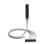
Front adapters - VIP-PA-FLK50/4X14/ 3,0M/S7 - 2322595
Please be informed that the data shown in this PDF Document is generated from our Online Catalog. Please find the complete data in the user's
documentation. Our General Terms of Use for Downloads are valid
(http://phoenixcontact.com/download)
VIP VARIOFACE front adapter, with connected system cables for SMATIC S7-300, 4 x 8 channels can be
connected, cable length: 3 m
Your advantages
Power supply via terminal blocks with spring-cage double connection
Can be screwed on with the I/O module
Encapsulated socket strips on the module side
Key Commercial Data
Packing unit
1 pc
GTIN
GTIN
4046356452335
Weight per Piece (excluding packing)
1,030.000 g
Custom tariff number
85444290
Country of origin
Germany
Technical data
Note
Type of note
Notes on operation
Note
Analog I/O cards
To avoid short-circuits, all wire bridges must be disconnected!
No voltage supply may be supplied to the front adapter!
Type of note
Notes on operation
Note
Digital I/O cards
Thanks to the existing wire bridge upon delivery, the input and output
bytes are non-isolated.
06/15/2020 Page 1 / 8
�https://www.phoenixcontact.com/us/products/2322595
Front adapters - VIP-PA-FLK50/4X14/ 3,0M/S7 - 2322595
Technical data
Ambient conditions
Ambient temperature (operation)
-20 °C ... 50 °C
Ambient temperature (storage/transport)
-20 °C ... 70 °C
Degree of protection
IP20
General
Max. permissible operating voltage
25 V AC
60 V DC
Max. permissible current
1 A (per path)
8 A (Separate power supply)
Mounting position
any
Standards and Regulations
Connection in acc. with standard
CUL
Standards/regulations
IEC 60664
DIN EN 50178
Rated insulation voltage
63 V
Rated surge voltage
0.6 kV
Insulation
Functional insulation
Pollution degree
2
Overvoltage category
II
Connection data
Connection name
Control side
Connection method
Plug connection
Note
Can be plugged onto 40-pos. I/O modules
Connection data 2
Connection name
Field level
Connection method
IDC/FLK socket strip
Number of connections
4
Number of positions
14
Pitch
2.54 mm
Connection data 3
Connection name
Supply
Connection method
Push-in connection
Stripping length
10 mm
Conductor cross section solid
0.2 mm² ... 2.5 mm²
Conductor cross section flexible
0.2 mm² ... 2.5 mm²
Conductor cross section AWG
24 ... 14
06/15/2020 Page 2 / 8
�https://www.phoenixcontact.com/us/products/2322595
Front adapters - VIP-PA-FLK50/4X14/ 3,0M/S7 - 2322595
Technical data
Cable
Conductor construction: Number of litz wires:
7
Single wire, material
Cu tin-plated
Single wire, cross section
0.14 mm²
External diameter
6.4 mm
Length of cable
3m
Shielding
no
Halogen-free cable
No
Max. conductor resistance
0.16 Ω/m
Supported controller
Controller
SIEMENS S7-300 / ET 200 M
- suitable I/O card
CPU 313C
CPU 313C-2PtP
CPU 313C-2DP
CPU 314C-2PtP
CPU 314C-2DP
6ES7 321-1BL00-0AA0
6ES7 322-1BL00-0AA0
6ES7 322-8BH01-0AB0
6ES7 322-8BH10-0AB0
6ES7 323-1BL00-0AA0
6ES7 331-7NF00-0AB0
6ES7 331-7NF10-0AB0
6ES7 331-7PF01-0AB0
6ES7 331-7PF11-0AB0
6ES7 350-2AH01-0AE0
6ES7 357-4AH01-0AE0
6ES7 331-1KF02-0AB0
Environmental Product Compliance
REACh SVHC
Lead 7439-92-1
China RoHS
Environmentally Friendly Use Period = 50 years
For details about hazardous substances go to tab “Downloads”, Category
“Manufacturer's declaration”
Drawings
06/15/2020 Page 3 / 8
�https://www.phoenixcontact.com/us/products/2322595
Front adapters - VIP-PA-FLK50/4X14/ 3,0M/S7 - 2322595
Circuit diagram
Classifications
eCl@ss
eCl@ss 10.0.1
27242292
eCl@ss 4.0
27060300
eCl@ss 4.1
27060300
eCl@ss 5.0
27061800
eCl@ss 5.1
27061800
eCl@ss 6.0
27249200
eCl@ss 7.0
27249290
eCl@ss 8.0
27249290
eCl@ss 9.0
27242292
ETIM
ETIM 4.0
EC002584
ETIM 5.0
EC002584
ETIM 6.0
EC002584
ETIM 7.0
EC002584
UNSPSC
UNSPSC 6.01
26121620
UNSPSC 7.0901
26121620
UNSPSC 11
26121620
06/15/2020 Page 4 / 8
�https://www.phoenixcontact.com/us/products/2322595
Front adapters - VIP-PA-FLK50/4X14/ 3,0M/S7 - 2322595
Classifications
UNSPSC
UNSPSC 12.01
26121620
UNSPSC 13.2
32151601
UNSPSC 18.0
32151601
UNSPSC 19.0
32151601
UNSPSC 20.0
32151601
UNSPSC 21.0
32151601
Approvals
Approvals
Approvals
UL Recognized / cUL Recognized / EAC / cULus Recognized
Ex Approvals
Approval details
UL Recognized
http://database.ul.com/cgi-bin/XYV/template/LISEXT/1FRAME/index.htm
Nominal voltage UN
50 V
Nominal current IN
1A
cUL Recognized
http://database.ul.com/cgi-bin/XYV/template/LISEXT/1FRAME/index.htm
Nominal voltage UN
50 V
Nominal current IN
1A
EAC
FILE E 238705
FILE E 238705
RU CDE.A*30.B00767
06/15/2020 Page 5 / 8
�https://www.phoenixcontact.com/us/products/2322595
Front adapters - VIP-PA-FLK50/4X14/ 3,0M/S7 - 2322595
Approvals
cULus Recognized
Accessories
Accessories
Controller board
Passive module - VIP-2/SC/2FLK14 (1-20) /S7 - 2315230
VARIOFACE interface module for Siemens SIMATIC® S7-300, for max. 16 channels with SIMATIC®-specific labeling (1
- 20), with screw connection, module width: 80.6 mm
Passive module - VIP-2/PT/2FLK14 (1-20) /S7 - 2903802
VARIOFACE interface module for Siemens SIMATIC® S7-300, for max. 16 channels with SIMATIC®-specific labeling (1
- 20), with push-in connection, module width: 82.5 mm
Passive module - FLKM-2FLK14/KDS3-MT/PPA/S7 - 2295062
VARIOFACE interface module for Siemens SIMATIC® S7-300, for max. 16 channels, with SIMATIC®-specific labeling (1
- 20), knife disconnect terminal block and test connection, module width: 113 mm
System connection - PLC-V8/FLK14/OUT - 2295554
V8 adapter for 8 x PLC-INTERFACE (6.2 mm), controller: PLC system cabling of output cards, connection 1: Screw
connection 1x, connection 2: IDC/FLK pin strip 1x 14-position, connection 3: Plug connection (Can be snapped onto 8x
PLC-INTERFACE terminals), number of channels: 8, control logic: positive switching
06/15/2020 Page 6 / 8
�https://www.phoenixcontact.com/us/products/2322595
Front adapters - VIP-PA-FLK50/4X14/ 3,0M/S7 - 2322595
Accessories
System connection - PLC-V8/FLK14/IN - 2296553
V8 adapter for 8 x PLC-INTERFACE (6.2 mm), controller: PLC system cabling of input cards, connection 1: Screw
connection 1x, connection 2: IDC/FLK pin strip 1x 14-position, connection 3: Plug connection (Can be snapped onto 8x
PLC-INTERFACE terminals), number of channels: 8, control logic: positive switching
System connection - PLC-V8L/FLK14/OUT - 2299660
V8 adapter for 8 x PLC-INTERFACE (14 mm), controller: PLC system cabling of output cards, connection 1: Screw
connection 1x, connection 2: IDC/FLK pin strip 1x 14-position, connection 3: Plug connection (Can be snapped onto 8x
PLC-INTERFACE terminals), number of channels: 8, control logic: positive switching
Passive module - VIP-3/SC/FLK14/8IM/PLC - 2322278
VARIOFACE sensor module, for connecting 8 pnp sensors
Passive module - VIP-3/PT/FLK14/8IM/PLC - 2904282
VARIOFACE sensor module, with push-in connection, for connecting 8 pnp sensors
Marker carrier cable
Cable marker carrier - KME - 0807083
Cable marker carrier, white, unlabeled, mounting type: Assembly with cable binders, cable diameter: > 5 mm, lettering
field size: 20 mm x 8 mm
06/15/2020 Page 7 / 8
�https://www.phoenixcontact.com/us/products/2322595
Phoenix Contact 2020 © - all rights reserved
http://www.phoenixcontact.com
06/15/2020 Page 8 / 8
�