AXL F BK PB
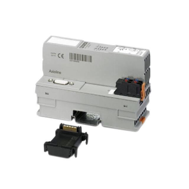
Axioline F bus coupler for PROFIBUS DP
Data sheet
8419_en_02
1
© PHOENIX CONTACT 2015-10-12
Description
The bus coupler represents the link between a PROFIBUS
network and the Axioline F system.
You can connect up to 63 Axioline F devices to an existing
PROFIBUS system with the help of the bus coupler.
Features of Axioline F
–
–
PROFIBUS features
–
–
–
–
–
–
–
–
–
–
–
Up to 63 additional Axioline F devices can be connected
Typical cycle time of the Axioline F local bus is around
10 μs
Diagnostic and status indicators
PROFIBUS connection via 9-pos. D-SUB female connector
Interface physics RS-485 for PROFIBUS
Electrical isolation between PROFIBUS interface and
logic
DP/V1 for Class 1 and Class 2 masters
Data transmission speed of 9.6 kbps up to 12 Mbps
(automatic detection)
Rotary encoding switches for setting the PROFIBUS
address
Dynamic configuration is supported
Supported PROFIBUS addresses 0 to 126
Device description using GSD file
I & M functions
This data sheet is only valid in association with the UM EN AXL F SYS INST user manual.
Make sure you always use the latest documentation.
It can be downloaded from the product at phoenixcontact.net/products.
Here you will also find the current GSD file.
�AXL F BK PB
2
Table of contents
1
Description .............................................................................................................................. 1
2
Table of contents ..................................................................................................................... 2
3
Ordering data .......................................................................................................................... 3
4
Technical data ......................................................................................................................... 4
5
Internal circuit diagram ............................................................................................................ 6
6
Connection of PROFIBUS and power supply .......................................................................... 7
6.1
Connecting PROFIBUS ......................................................................................................... 7
6.2
Mains termination resistors .................................................................................................... 7
6.3
Connecting the supply voltage - terminal point assignment............................................................. 7
7
Connection example................................................................................................................ 7
8
Configuration via rotary encoding switch ................................................................................. 8
9
Parameter data ........................................................................................................................ 8
10
Local status and diagnostic indicators ..................................................................................... 9
11
Reset button .......................................................................................................................... 11
12
Service interface.................................................................................................................... 11
13
Substitute value behavior ...................................................................................................... 11
14
Firmware functions ................................................................................................................ 11
8419_en_02
PHOENIX CONTACT
2
�AXL F BK PB
3
Ordering data
Description
Type
Order No.
Pcs./Pkt.
Axioline F bus coupler for PROFIBUS DP (including bus base module and
connector)
AXL F BK PB
2688530
1
Accessories
Type
Order No.
Pcs./Pkt.
Axioline F bus base module for housing type BK (Replacement item)
AXL BS BK
2701422
5
Axioline F short power connector (for e.g., AXL F BK ...) (Replacement
item)
AXL CN S/UL
2701421
5
Zack marker strip for Axioline F (device labeling), in 2 x 20.3 mm pitch, un- ZB 20,3 AXL UNPRINTED
printed, 25-section, for individual labeling with B-STIFT 0.8, X-PEN, or
CMS-P1-PLOTTER (Marking)
0829579
25
Zack marker strip, flat, in 10 mm pitch, unprinted, 10-section, for individual
labeling with M-PEN 0,8, X-PEN, or CMS-P1-PLOTTER (Marking)
ZBF 10/5,8 AXL UNPRINTED
0829580
50
Insert label, Roll, white, unlabeled, can be labeled with: THERMOMARK
ROLL, THERMOMARK ROLL X1, THERMOMARK X, THERMOMARK
S1.1, Mounting type: snapped into marker carrier, Lettering field: 35 x 18.7
mm (Marking)
EMT (35X18,7)R
0801831
1
D-SUB plug, 9-pos., pin, assignment: 3, 5, 6, 8; two M12 cable glands (Bcoded) under 35°. Bus system: PROFIBUS DP up to 12 Mbps. Termination
resistor via separate M12 terminator. (Connector/Adapter)
SUBCON-PLUS-PROFIB/35/M12
2902320
1
D-SUB connector, 9-pos., male connector, cable entry < 35°, bus system:
PROFIBUS DP up to 12 Mbps, termination resistor can be switched on via
slide switch, pin assignment: 3, 5, 6, 8; screw connection terminal blocks
(Connector/Adapter)
SUBCON-PLUS-PROFIB/SC2
2708232
1
D-SUB connector, 9-pos., male connector, cable entry < 90°, bus system:
PROFIBUS DP up to 12 Mbps, termination resistor can be switched on via
slide switch, pin assignment: 3, 5, 6, 8; IDC terminal block connection
(Connector/Adapter)
SUBCON-PLUS-PROFIB/90/IDC
2313672
1
D-SUB connector, 9-pos., male connector, cable entry < 90°, bus system:
PROFIBUS DP up to 12 Mbps, termination resistor can be switched on via
slide switch, pin assignment: 3, 5, 6, 8; screw connection terminal blocks
(Connector/Adapter)
SUBCON-PLUS-PROFIB/90/SC
2313698
1
D-SUB connector, 9-pos., male connector, axial version with two cable en- SUBCON-PLUS-PROFIB/AX/SC
tries, bus system: PROFIBUS DP up to 12 Mbps, termination resistor can
be switched on via slide switch, pin assignment: 3, 5, 6, 8; screw connection terminal blocks (Connector/Adapter)
2744380
1
Connecting cable, for connecting the controller to a PC for PC Worx and
LOGIC+, USB A to micro USB B, 2 m in length. (Cable/conductor)
CAB-USB A/MICRO USB B/2,0M
2701626
1
Documentation
Type
Order No.
Pcs./Pkt.
User manual, English,
Diagnostic and firmware functions of the AXL F BK PB bus coupler
UM EN AXL F BK PB
-
-
User manual, English, Axioline F: System and installation
UM EN AXL F SYS INST
-
-
User manual, English, Axioline F: Diagnostic registers, and error messages UM EN AXL F SYS DIAG
-
-
8419_en_02
PHOENIX CONTACT
3
�AXL F BK PB
4
Technical data
Dimensions (nominal sizes in mm)
122,4
12
0 2
8 10
0 2
4 6
89
S2
4 6
S1
125,9
74
45
Width
45 mm
Height
125.9 mm
Depth
74 mm
Note on dimensions
The depth is valid when a TH 35-7.5 DIN rail is used (according to EN 60715).
General data
Color
traffic grey A RAL 7042
Weight
175 g (with connector and bus base module)
Ambient temperature (operation)
-25 °C ... 60 °C (Mounting position: wall mounting on horizontal DIN rail)
-25 °C ... 55 °C (Mounting position: any)
Ambient temperature (storage/transport)
-40 °C ... 85 °C
Permissible humidity (operation)
5 % ... 95 % (non-condensing)
Permissible humidity (storage/transport)
5 % ... 95 % (non-condensing)
Air pressure (operation)
70 kPa ... 106 kPa (up to 3000 m above sea level)
Air pressure (storage/transport)
70 kPa ... 106 kPa (up to 3000 m above sea level)
Degree of protection
IP20
Protection class
III, IEC 61140, EN 61140, VDE 0140-1
Mounting position
Any (observe temperature derating)
Connection data
Designation
Axioline F connector
Connection method
Push-in connection
Conductor cross section solid / stranded
0.2 mm² ... 1.5 mm² / 0.2 mm² ... 1.5 mm²
Conductor cross section [AWG]
24 ... 16
Stripping length
8 mm
Please observe the information provided on conductor cross sections in the “Axioline F: system and installation” user manual.
Interface PROFIBUS DP
Number
1
Connection method
9-pos. D-SUB (socket)
Number of positions
9
Transmission speed
9,6 kBit/s ... 12 MBit/s
8419_en_02
PHOENIX CONTACT
4
�AXL F BK PB
Interface Axioline F local bus
Connection method
Bus base module
Transmission speed
100 MBit/s
Interface Service
Number
1
Connection method
Micro USB type B
System limits of the bus coupler
Amount of process data
max. 488 Byte (per station)
max. 244 Byte (Input)
max. 244 Byte (Output)
Number of parameter data
max. 244 Byte
Number of configuration data
max. 244 Byte
IN and OUT process data for I/O modules that can be aligned
488 Byte
IN process data for I/O modules that can be aligned
244 Byte
OUT process data for I/O modules that can be aligned
244 Byte
Number of supported devices
max. 63 (per station)
NOTE: Electronics may be damaged when overloaded
Observe the logic current consumption of each device when configuring an Axioline F station. It is specified in every module-specific data
sheet. The current consumption can differ depending on the individual module. The permissible number of devices that can be connected
therefore depends on the specific station structure.
Supply of the bus coupler
Supply of communications power UL
24 V DC
Maximum permissible voltage range
19.2 V DC ... 30 V DC (including all tolerances, including ripple)
Current supply at UBus
2A
Current consumption from UL
typ. 101 mA (without I/Os and UL = 24 V)
max. 567 mA (with 2 A at UBus for the I/Os and UL = 24 V)
Power consumption at UL
typ. 2.5 W (without I/Os)
max. 13.7 W (with 2 A load at UBus for the I/Os)
NOTE: Electronics may be damaged when overloaded
Provide external fuses for the 24 V UL area. The power supply unit must be able to supply four times the nominal current of the external fuse
to ensure that it blows in the event of an error.
Error messages to the higher level control or computer system
Diagnostic alarms
Mechanical tests
Vibration resistance in acc. with EN 60068-2-6/IEC 60068-2-6
5g
Shock in acc. with EN 60068-2-27/IEC 60068-2-27
30g, 11 ms period, half-sine shock pulse
Continuous shock according to EN 60068-2-27/IEC 60068-2-27
10g
Conformance with EMC Directive 2004/108/EC
Noise immunity test in accordance with EN 61000-6-2
Electrostatic discharge (ESD) EN 61000-4-2/IEC 61000-4-2
Criterion B; 6 kV contact discharge, 8 kV air discharge
Electromagnetic fields EN 61000-4-3/IEC 61000-4-3
Criterion A; Field intensity: 10 V/m
Fast transients (burst) EN 61000-4-4/IEC 61000-4-4
Criterion B, 2 kV
Transient surge voltage (surge) EN 61000-4-5/IEC 61000-4-5
Criterion B; DC supply lines: ±0.5 kV/±0.5 kV (symmetrical/asymmetrical); fieldbus cable shield: ±1 kV
Conducted interference EN 61000-4-6/IEC 61000-4-6
Criterion A; Test voltage 10 V
Noise emission test according to EN 61000-6-3
Radio interference properties EN 55022
8419_en_02
Class B
PHOENIX CONTACT
5
�AXL F BK PB
Approvals
For the latest approvals, please visit phoenixcontact.net/products.
5
Internal circuit diagram
Key:
BF
FE
PROFIBUS
RDY
FE
Service
Reset
Local bus
FS
FN
D-SUB
D
5V
E
D-SUB
3.3V
FE
Service
Functional earth ground
Service interface
Reset button
Axioline F local bus
(hereinafter referred to as local bus)
D-SUB connection
Power supply unit with electrical isolation
mC
Reset
µC
Local bus
Power supply unit
XXX
UBus
Microcontroller
XXX
LED
UL
3.3 V
UBus
24 V
Electrically isolated areas
UL
24 V
Figure 1
8419_en_02
Internal wiring of the terminal points
PHOENIX CONTACT
6
�AXL F BK PB
6
Connection of PROFIBUS and power supply
6.1
Connecting PROFIBUS
6.3
Connect PROFIBUS to the bus coupler using a 9-pos. DSUB connector (see Ordering data). For the pin assignment,
please refer to the figure and the table.
Pin
1
2
3
4
5
6
7
8
9
6.2
b2
b1
b2
Terminal point assignment
D-SUB connector pin assignment
Assignment
Reserved
Reserved
RxD/TxD-P (receive/transmit data +), cable B
CNTR-P (control signal for repeater), direction control
DGND (reference potential to 5 V)
VP (+5 V supply voltage for termination resistors)
Reserved
RxD/TxD-N (receive/transmit data –), cable A
Reserved
Termi- Color
Assignment
nal
point
Supply voltage input
a1, a2
Red
24 V DC Supply of the logic voltage
(internally jumpered)
(UL)
b1, b2
Blue
GND
Reference potential of the
supply voltage (internally
jumpered)
7
Connection example
PROFIBUS DP
Mains termination resistors
BF
FS
FN
S1
UL
Figure 4
S2
D
E
0 2
0 2
4 6
24 V DC +
(UL)
RDY
4 6
Since PROFIBUS DP is a serial bus system in a line or tree
structure, the individual branches must be terminated using
a termination resistor. The bus coupler does not have a resistor of this type. For further information, please refer to
your PROFIBUS documentation. Phoenix Contact recommends the use of the SUBCON-PLUS-PROFIB connector,
Order No. 2744348. This connector has a termination resistor that can be connected.
8419_en_02
b1
12
Figure 2
Figure 3
a1
a2
89
7
6
5
4
3
2
1
a1
a2
8 10
9
8
Connecting the supply voltage - terminal point
assignment
Connection of the cables
PHOENIX CONTACT
7
�AXL F BK PB
8
Configuration via rotary encoding
switch
The address is set using two rotary encoding switches.
Switch S1 is used to set the position in tens (x10) and S2 is
used to set the position in units (x1). Addresses can be set
between 0 and 126. The figure shows the address setting
74.
0
S1
2
12
10
4
8
6
x10
0
S2
2
4
9 8
6
x1
Figure 5
9
(ADDRESS) rotary encoding switches
Parameter data
During configuration, please note that connected digital input/output modules also use
parameter data from PROFIBUS. Please refer
to the GSD file for the parameter data length.
8419_en_02
PHOENIX CONTACT
8
�AXL F BK PB
10
Local status and diagnostic indicators
BF
FS
FN
RDY
D
E
UL
Figure 6
Local status and diagnostic indicators
Designation
UL
Color
Green
BF
Red
FS
Red
FN
Red
RDY
Green/
yellow/
red
8419_en_02
Meaning
ULogic
State
ON
OFF
Bus Fault
ON
OFF
Failure Select ON
OFF
Failure Number Flashing
Ready
OFF
Green
ON
Flashing
green/
yellow
Yellow
ON
Yellow
flashing
Flashing
yellow/
red
Red ON
Red
flashing
OFF
Description
Communications power supply present.
Communications power supply not present.
No communication on PROFIBUS
No error
If FS is on, FN indicates the error type
If FS is not on, FN indicates the error number
The number of flashing pulses indicates the error type or the error
number, depending on whether FS is on or not
No error
Device is ready for operation.
Communications power undervoltage or surge voltage
Overtemperature
Firmware/bus coupler is booting
Firmware update is being performed.
Firmware update has failed.
Rotary encoding switches are set to an invalid/reserved position.
Firmware update error; wrong or faulty firmware loaded; restart the
device.
Device is not ready for operation.
PHOENIX CONTACT
9
�AXL F BK PB
Designation
D
Color
Green/
yellow/
red
Meaning
Diagnostics
State
Green
ON
Green
flashing
Yellow
ON
Yellow
flashing
Flashing
yellow/
red
Red
flashing
Red ON
E
8419_en_02
Yellow/ Error
red
Yellow
ON
Red ON
OFF
Description
The station is ready for operation, communication within the station
is OK.
All data is valid. There are no faults.
The station is ready for operation, communication within the station
is OK.
The data is not valid. Valid data from the controller/higher-level network not available.
There is no fault in the module.
The station is ready for operation, no data exchange taking place.
Access from Startup+ in I/O check mode
Local bus error during active I/O check
Local bus error on startup
General local bus error
Communication error
Local bus device has been removed or configured device is missing.
Reset at a local bus device
Serious device error at a local bus device (local bus device can no
longer be reached)
I/O warning at a local bus device
I/O error at a local bus device
No I/O messages present.
PHOENIX CONTACT
10
�AXL F BK PB
11
Reset button
12
The reset button is located beneath the top marking label on
the bus coupler.
Service interface
The service interface is located beneath the top marking
field on the bus coupler.
The service interface is used for later applications.
1
1
2
2
Figure 7
Reset button
Figure 8
1
2
Labeling field
Reset button
The reset button has the following function:
– Restarting the bus coupler
1
2
Service interface
Labeling field
Service interface
The bus coupler is restarted when the button is pressed during operation.
13
The outputs of the station are set to the parameterized substitute values.
If PROFIBUS communication fails or an error occurs in the
local bus, all outputs of the station are set to the substitute
values previously parameterized on the module.
The process image of the inputs is not re-read.
Substitute value behavior
For the possible substitute values of a module, please refer to the relevant module-specific data sheet.
14
Firmware functions
Function
Process and parameter data
Total amount of process data
- IN and OUT
- IN
- OUT
Amount of process data for alignable I/O terminals
- IN and OUT
- IN
8419_en_02
AXL F BK PB AXL BK PB
FW 2.0 or
FW 1.0 or
later
later
IL PB BK DI8
DO4/EF-PAC
488 bytes,
maximum
244 bytes,
maximum
244 bytes,
maximum
488 bytes,
maximum
244 bytes,
maximum
244 bytes,
maximum
488 bytes,
maximum
244 bytes,
maximum
244 bytes,
maximum
488 bytes,
maximum
244 bytes,
maximum
488 bytes,
maximum
244 bytes,
maximum
486 bytes,
maximum
243 bytes,
maximum
PHOENIX CONTACT
11
�AXL F BK PB
Function
- OUT
Amount of parameter data
- Total
- For alignable I/O terminals
Amount of configuration data
- Total
- For alignable I/O terminals
Other
Number of PCP devices
Supports DP/V1 read and write (acyclic communication), Class 1 and
Class 2 master
Communication with PCP modules via "normal" process data (DP/V0)
Transmission invoke ID
Parameterization of several I/Os via dialog boxes in the configuration tool
Dynamic configuration (reserving I/Os in the PLC)
Specification of fail-safe values via the configuration tool
AXL F BK PB
FW 2.0 or
later
244 bytes,
maximum
AXL BK PB
FW 1.0 or
later
244 bytes,
maximum
IL PB BK DI8
DO4/EF-PAC
244 bytes,
maximum
233 bytes,
maximum
244 bytes,
maximum
233 bytes,
maximum
244 bytes,
maximum
230 bytes,
maximum
244 bytes,
maximum
244 bytes,
maximum
244 bytes,
maximum
244 bytes,
maximum
244 bytes,
maximum
239 bytes,
maximum
Yes
Yes
max. 16
Yes
Yes
Yes
Yes
Yes
Yes
Yes
Yes
Yes
Byte rotation for the IB IL 24 DI 16-PAC and IB IL 24 DO 16-PAC
Byte rotation for the IB IL 24 DI 32-PAC and IB IL 24 DO 32-PAC
Operation in the event of module failure in the local bus
Acknowledgment of local bus stops via the application program
Acknowledging bus stops either automatically or via the application program
Diagnostics in bus coupler format
Channel-specific diagnostics
Diagnostics in identification format
Diagnostics as status PDU
Stop behavior can be set via parameter telegram
I & M functions
PROFIsafe support
IO-Link call
Yes
Yes
automatic
Yes
No
Yes (hold last
value or zero)
Yes
No
automatic
Yes
Yes
Yes
Yes
Yes
Yes
No
No
Yes
Yes
Yes
Yes
No
Yes
No
No
Selection of the diagnostic format in the configuration tool
No
No
243 bytes,
maximum
Yes
Yes
Yes
Yes
Yes
Yes
Yes
Yes
Yes
Yes
Yes
Yes
Yes (FW 2.0 or
later)
Yes
For more detailed information on the bus coupler functions described, please refer to the
corresponding documentation.
8419_en_02
PHOENIX CONTACT GmbH & Co. KG • 32823 Blomberg • Germany
phoenixcontact.com
12
�