https://www.phoenixcontact.com/us/products/2688598
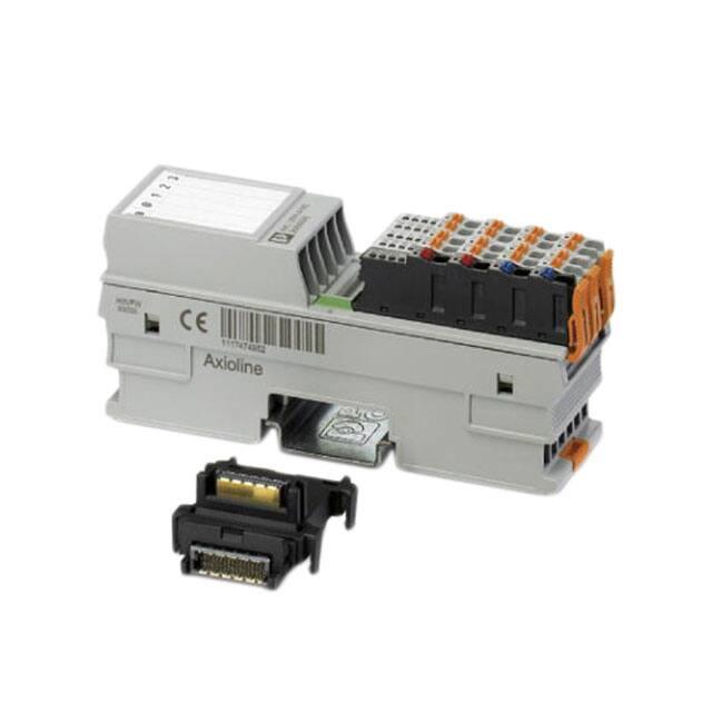
I/O module - AXL F UTH4 1H - 2688598
Please be informed that the data shown in this PDF Document is generated from our Online Catalog. Please find the complete data in the user's
documentation. Our General Terms of Use for Downloads are valid
(http://phoenixcontact.com/download)
Axioline F, Temperature recording module, Analog inputs: 4 (4 inputs for thermocouples or linear voltage, plus 1
input -5 V to +5 V), connection method: 2-wire (shielded, twisted pair), transmission speed in the local bus: 100
Mbps, degree of protection: IP20, including bus base module and Axioline F connectors
Product Description
The module is designed for use within an Axioline F station.
It is used to acquire signals from standard thermocouples in industrial applications.
The module supports various types of thermocouple conforming to DIN EN 60584-1 and DIN 46710 as well as linear voltages from -100 mV to
+100 mV.
It also offers a voltage input from -5 V to +5 V.
Heating currents can be monitored here, for example, using a measuring transducer.
Both Pt 100 inputs (CJ1 and CJ2) can each be used as a sensor input or as an external cold junction.
Your advantages
4 analog input channels to connect thermocouples or linear voltages from -100 mV to +100 mV
1 analog input channel for the connection of voltages from -5 V to +5 V
Connection of sensors in 2-wire technology
Internal detection and compensation of cold junction temperature (can be parameterized)
External connection of Pt 100 cold junction sensors possible
High level of accuracy (typically ±0.01 % sensor type K)
High level of accuracy, even in various mounting positions, thanks to built-in space compensation of the internal cold junction
High temperature stability (typically 8 ppm/K)
High resistance to electromagnetic interference (Class A)
"Channel Scout" function
Device rating plate stored
Diagnostic and status indicators
Installation monitoring with indication via diagnostic LED for each channel
Key Commercial Data
Packing unit
1 pc
11/08/2019 Page 1 / 16
�https://www.phoenixcontact.com/us/products/2688598
I/O module - AXL F UTH4 1H - 2688598
GTIN
GTIN
4046356780117
Weight per Piece (excluding packing)
200.000 g
Custom tariff number
85389091
Country of origin
Germany
Technical data
Dimensions
Width
35 mm
Height
126.1 mm
Depth
54 mm
Note on dimensions
The depth is valid when a TH 35-7,5 DIN rail is used (according to
EN 60715).
Ambient conditions
Ambient temperature (operation)
-25 °C ... 60 °C
Ambient temperature (storage/transport)
-40 °C ... 85 °C
Permissible humidity (operation)
5 % ... 95 % (non-condensing)
Permissible humidity (storage/transport)
5 % ... 95 % (non-condensing)
Air pressure (operation)
70 kPa ... 106 kPa (up to 3000 m above sea level)
Air pressure (storage/transport)
70 kPa ... 106 kPa (up to 3000 m above sea level)
Degree of protection
IP20
Connection data
Designation
Axioline F connector
Connection method
Push-in connection
Note on the connection method
Please observe the information provided on conductor cross sections in
the “Axioline F: system and installation” user manual.
Conductor cross section solid min.
0.2 mm²
Conductor cross section solid max.
1.5 mm²
Conductor cross section flexible min.
0.2 mm²
Conductor cross section flexible max.
1.5 mm²
Conductor cross section AWG min.
24
Conductor cross section AWG max.
16
Stripping length
8 mm
General
Mounting type
DIN rail
Net weight
144 g
Note on weight specifications
with connectors and bus base module
11/08/2019 Page 2 / 16
�https://www.phoenixcontact.com/us/products/2688598
I/O module - AXL F UTH4 1H - 2688598
Technical data
Interfaces
Designation
Axioline F local bus
No. of channels
2
Connection method
Bus base module
Transmission speed
100 Mbps
Axioline potentials
Designation
Axioline F local bus supply (UBus)
Supply voltage
5 V DC (via bus base module)
Current consumption
typ. 112 mA
max. 160 mA
Power consumption
typ. 0.54 W (logic)
max. 0.8 W (logic)
Designation
Supply for analog modules (UA)
Supply voltage
24 V DC
Supply voltage range
19.2 V DC ... 30 V DC (including all tolerances, including ripple)
Current consumption
typ. 23 mA
max. 40 mA
Power consumption
max. 0.96 W (Peripherals)
typ. 1.05 W (entire device)
max. 1.76 W (entire device)
Type of protection
Surge protection of the supply voltage
Polarity reversal protection of the supply voltage
Transient protection
Analog inputs
Number of inputs
4 +1 (4 inputs for thermocouples or linear voltage, plus 1 input -5 V to
+5 V)
Input name
Analog inputs
Description of the input
Inputs for thermocouples or linear voltage
Connection method
Spring-cage connection with direct connector-in method
Connection technology
2-wire (shielded, twisted pair)
Sensor types (RTD) that can be used
Pt 100 (2 external cold junctions, can also be used as a sensor input)
Measuring principle
Sigma/Delta process
Measured value representation
16 bits (15 bits + sign bit)
Resolution A/D
24 bit
Type of protection
Short-circuit protection, overload protection of the inputs
Transient protection of inputs
Input filter time
40 ms
11/08/2019 Page 3 / 16
�https://www.phoenixcontact.com/us/products/2688598
I/O module - AXL F UTH4 1H - 2688598
Technical data
Electrical isolation
Test section
5 V communications power (logic), 24 V supply (I/O) 500 V AC 50 Hz 1
min.
5 V supply (logic)/functional earth ground 500 V AC 50 Hz 1 min.
24 V supply (I/O) / functional earth ground 500 V AC 50 Hz 1 min.
Standards and Regulations
Mechanical tests
Vibration resistance in acc. with EN 60068-2-6/IEC 60068-2-6 5g
Shock in acc. with EN 60068-2-27/IEC 60068-2-27 30g
Continuous shock according to EN 60068-2-27/IEC 60068-2-27 10g
Protection class
III, IEC 61140, EN 61140, VDE 0140-1
Environmental Product Compliance
Lead 7439-92-1
Drawings
11/08/2019 Page 4 / 16
�https://www.phoenixcontact.com/us/products/2688598
I/O module - AXL F UTH4 1H - 2688598
Connection diagram
Connection example: absolute temperature measurement
11/08/2019 Page 5 / 16
�https://www.phoenixcontact.com/us/products/2688598
I/O module - AXL F UTH4 1H - 2688598
Connection diagram
Pt 100 detection
11/08/2019 Page 6 / 16
�https://www.phoenixcontact.com/us/products/2688598
I/O module - AXL F UTH4 1H - 2688598
Connection diagram
11/08/2019 Page 7 / 16
�https://www.phoenixcontact.com/us/products/2688598
I/O module - AXL F UTH4 1H - 2688598
Connection diagram
Differential temperature measurement
11/08/2019 Page 8 / 16
�https://www.phoenixcontact.com/us/products/2688598
I/O module - AXL F UTH4 1H - 2688598
Connection diagram
Thermocouple detection with external cold junction compensation at channel 1
11/08/2019 Page 9 / 16
�https://www.phoenixcontact.com/us/products/2688598
I/O module - AXL F UTH4 1H - 2688598
Block diagram
Internal wiring of the terminal points
11/08/2019 Page 10 / 16
�https://www.phoenixcontact.com/us/products/2688598
I/O module - AXL F UTH4 1H - 2688598
Dimensional drawing
Classifications
eCl@ss
eCl@ss 4.0
27240405
eCl@ss 4.1
27240405
eCl@ss 5.0
27242201
eCl@ss 5.1
27242601
eCl@ss 6.0
27242600
eCl@ss 7.0
27242601
eCl@ss 8.0
27242601
eCl@ss 9.0
27242601
11/08/2019 Page 11 / 16
�https://www.phoenixcontact.com/us/products/2688598
I/O module - AXL F UTH4 1H - 2688598
Classifications
ETIM
ETIM 3.0
EC001599
ETIM 4.0
EC001599
ETIM 5.0
EC001596
ETIM 6.0
EC001596
ETIM 7.0
EC001596
UNSPSC
UNSPSC 6.01
43172015
UNSPSC 7.0901
43201404
UNSPSC 11
39121311
UNSPSC 12.01
39121311
UNSPSC 13.2
32151602
Approvals
Approvals
Approvals
DNV GL / KR / NK / ABS / BSH / RINA / UL Listed / cUL Listed / LR / PRS / BV / cULus Listed
Ex Approvals
Approval details
DNV GL
https://approvalfinder.dnvgl.com/
TAA00000DF
KR
http://www.krs.co.kr/eng/main/main.aspx
HMB17372-AC002
NK
http://www.classnk.or.jp/hp/en/
14A006
ABS
http://www.eagle.org/eagleExternalPortalWEB/
18-HG1767360-PDA
11/08/2019 Page 12 / 16
�https://www.phoenixcontact.com/us/products/2688598
I/O module - AXL F UTH4 1H - 2688598
Approvals
BSH
http://www.bsh.de/de/index.jsp
840
RINA
http://www.rina.org/en
ELE256518XG
UL Listed
http://database.ul.com/cgi-bin/XYV/template/LISEXT/1FRAME/index.htm
FILE E 238705
cUL Listed
http://database.ul.com/cgi-bin/XYV/template/LISEXT/1FRAME/index.htm
FILE E 238705
LR
http://www.lr.org/en
14-20019
PRS
http://www.prs.pl/
TE/2239/880590/19
BV
http://www.veristar.com/portal/veristarinfo/generalinfo/
approved/approvedProducts/equipmentAndMaterials
36433/B0 BV
cULus Listed
Accessories
Accessories
Device marking
11/08/2019 Page 13 / 16
�https://www.phoenixcontact.com/us/products/2688598
I/O module - AXL F UTH4 1H - 2688598
Accessories
Insert label - EMT (35X28)R - 0801602
Insert label, Roll, white, unlabeled, can be labeled with: THERMOMARK ROLLMASTER 300/600, THERMOMARK X1.2,
THERMOMARK ROLL X1, THERMOMARK ROLL 2.0, THERMOMARK ROLL, mounting type: snapped into marker
carrier, lettering field size: 35 x 28 mm, Number of individual labels: 500
DIN rail connector
Bus connector - AXL F BS H - 2700992
Axioline F bus base module for housing type H
Feed-through terminal block
Thermoelectric voltage terminal block pair - MTKD-CU/CUNI - 3100059
Thermoelectric voltage terminal block pair, TC type T, nom. voltage: 400 V, nominal current: 1 A, connection method:
Screw connection, number of connections: 4, number of positions: 2, cross section: 0.2 mm² - 4 mm², AWG: 24 - 12,
width: 10.4 mm, color: gray, mounting type: NS 35/7,5, NS 35/15, NS 32
Thermoelectric voltage terminal block pair - MTKD-FE/CUNI - 3100046
Thermoelectric voltage terminal block pair, TC type J, nom. voltage: 400 V, nominal current: 1 A, connection method:
Screw connection, number of connections: 4, number of positions: 2, cross section: 0.2 mm² - 4 mm², AWG: 24 - 12,
width: 10.4 mm, color: gray, mounting type: NS 35/7,5, NS 35/15, NS 32
Thermoelectric voltage terminal block pair - MTKD-NICR/CUNI - 3100075
Thermoelectric voltage terminal block pair, TC type E, nom. voltage: 400 V, nominal current: 1 A, connection method:
Screw connection, number of connections: 4, number of positions: 2, cross section: 0.2 mm² - 4 mm², AWG: 24 - 12,
width: 10.4 mm, color: gray, mounting type: NS 35/7,5, NS 35/15, NS 32
11/08/2019 Page 14 / 16
�https://www.phoenixcontact.com/us/products/2688598
I/O module - AXL F UTH4 1H - 2688598
Accessories
Thermoelectric voltage terminal block pair - MTKD-NICR/NI - 3100062
Thermoelectric voltage terminal block pair, TC type K, nom. voltage: 400 V, nominal current: 1 A, connection method:
Screw connection, number of connections: 4, number of positions: 2, cross section: 0.2 mm² - 4 mm², AWG: 24 - 12,
width: 10.4 mm, color: gray, mounting type: NS 35/7,5, NS 35/15, NS 32
Thermoelectric voltage terminal block pair - MTKD-E-CU/A-CU - 3100091
Thermoelectric voltage terminal block pair, TC type R, nom. voltage: 400 V, nominal current: 1 A, connection method:
Screw connection, number of connections: 4, number of positions: 2, cross section: 0.2 mm² - 4 mm², AWG: 24 - 12,
width: 10.4 mm, color: gray, mounting type: NS 35/7,5, NS 35/15, NS 32
Thermoelectric voltage terminal block pair - MTKD-S-CU/E-CU - 3100101
Thermoelectric voltage terminal block pair, TC type B, nom. voltage: 400 V, nominal current: 1 A, connection method:
Screw connection, number of connections: 4, number of positions: 2, cross section: 0.2 mm² - 4 mm², AWG: 24 - 12,
width: 10.4 mm, color: gray, mounting type: NS 35/7,5, NS 35/15, NS 32
Shield connection
Shield connection - AXL SHIELD SET - 2700518
Axioline shield connection set (contains 2 shield bus holders and 2 SK 5 shield connection clamps)
Terminal marking
11/08/2019 Page 15 / 16
�https://www.phoenixcontact.com/us/products/2688598
I/O module - AXL F UTH4 1H - 2688598
Accessories
Zack marker strip - ZB 20,3 AXL UNPRINTED - 0829579
Zack marker strip for Axioline F (device labeling), in 2 x 20.3 mm pitch, unprinted, 25-section, for individual labeling with
B-STIFT 0.8, X-PEN, or CMS-P1-PLOTTER
Zack Marker strip, flat - ZBF 10/5,8 AXL UNPRINTED - 0829580
Zack Marker strip, flat, Strip, white, unlabeled, can be labeled with: PLOTMARK, CMS-P1-PLOTTER, mounting type:
snap into flat marker groove, for terminal block width: 10.15 mm, lettering field size: 4 of 10.15 x 5 mm and 1 of 5.8 x 5
mm, Number of individual labels: 50
Phoenix Contact 2019 © - all rights reserved
http://www.phoenixcontact.com
11/08/2019 Page 16 / 16
�