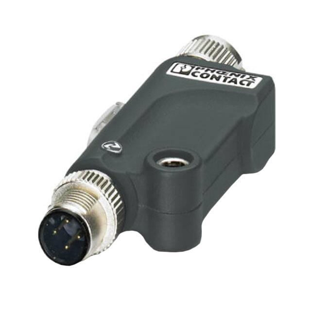
AXL E IOL AO1 U M12 S
Axioline E IO-Link/analog converter for connecting
an analog actuator, 0 V ... 10 V, straight version
Data sheet
8595_en_04
1
© PHOENIX CONTACT 2015-04-28
Description
The IO-Link/analog converter is an IO-Link slave that converts the IO-Link protocol into analog signals.
It therefore offers the option of transmitting signals to analog
actuators via an IO-Link master.
Features
–
–
–
–
–
–
–
–
–
Straight version
1 IO-Link interface
1 analog output
Connection of the actuator in 3-wire technology
Voltage range: 0 V ... 10 V
IO-Link and actuator connections via M12 connectors
FE connection for local connection to functional earth
ground
Supply of the module electronics and the actuator via
the IO-Link interface of the IO-Link master
Diagnostic indicator
Make sure you always use the latest documentation.
It can be downloaded from the product at phoenixcontact.net/products.
�AXL E IOL AO1 U M12 S
2
Table of contents
1
Description .............................................................................................................................. 1
2
Table of contents ..................................................................................................................... 2
3
Ordering data .......................................................................................................................... 3
4
Technical data ......................................................................................................................... 3
5
Additional tables ...................................................................................................................... 5
6
Internal circuit diagram ............................................................................................................ 5
7
Pin assignment ........................................................................................................................ 6
7.1
Connections on the device ..................................................................................................... 6
7.2
Pin assignment of the IO-Link interface ..................................................................................... 6
7.3
Pin assignment of the analog output ......................................................................................... 6
8
Connection notes .................................................................................................................... 6
9
Connection example................................................................................................................ 6
10
Assembly................................................................................................................................. 7
11
Local status indicator............................................................................................................... 7
12
Process data............................................................................................................................ 8
12.1 IN process data ................................................................................................................... 8
12.2 OUT process data................................................................................................................ 9
12.3 Parameterization via OUT process data .................................................................................... 9
12.4 Example ........................................................................................................................... 9
13
Significant values in various formats...................................................................................... 10
13.1 IB IL format ...................................................................................................................... 10
13.2 S7-compatible format ......................................................................................................... 10
14
IO-Link objects ...................................................................................................................... 11
14.1 Overview of the objects ....................................................................................................... 11
14.2 Parameterization (80hex: ParaWord) ....................................................................................... 12
8595_en_04
PHOENIX CONTACT
2
�AXL E IOL AO1 U M12 S
3
Ordering data
Description
Type
Order No.
Pcs. / Pkt.
Axioline E IO-Link/analog converter for connecting an analog actuator,
0 V ... 10 V, M12 fast connection technology, straight version
AXL E IOL AO1 U M12 S
2700350
1
4
Technical data
Dimensions (nominal sizes in mm)
79,5
29
16,5
16,6
28
50
Width
16.6 mm
Height
29 mm
Depth
79.5 mm
General data
Weight
34 g
Ambient temperature (operation)
-25 °C ... 60 °C
Ambient temperature (storage/transport)
-25 °C ... 85 °C
Permissible humidity (operation)
5 % ... 95 %
Permissible humidity (storage/transport)
5 % ... 95 %
Air pressure (operation)
70 kPa ... 106 kPa (up to 3000 m above sea level)
Air pressure (storage/transport)
70 kPa ... 106 kPa (up to 3000 m above sea level)
Degree of protection
IP65/67
Protection class
III, IEC 61140, EN 61140, VDE 0140-1
Pollution degree
2
IO-Link
Specification
V1.1.1
Protection against polarity reversal
Yes
Transmission speed
230,4 kBit/s (COM3)
Frame type
1
Cycle Time
min. 2 ms
Process data update
2 ms
Amount of process data
16 Bit (Input data), 16 Bit (Output data)
IO-Link ports
Number of ports
1
Connection method
M12 connector, A-coded
8595_en_04
PHOENIX CONTACT
3
�AXL E IOL AO1 U M12 S
IO-Link port supply
Typical current consumption
16.5 mA ±15% (at 24 V DC)
Current consumption
max. 135 mA
Protection against polarity reversal
Yes
Short-circuit protection
Yes
Overload protection
Yes
I/O supply voltage
24 V DC
This supply voltage is provided via the IO-Link interface of the IO-Link
Sensor supply voltage
24 V DC (max. 100 mA)
This supply voltage is provided via the I/O supply voltage.
master.
Analog output
Number of outputs
1 (voltage)
Connection method
M12 connector, A-coded
Connection method
3-conductor
Voltage output signal
0 V ... 10 V
Load/output load voltage output
min. 10 kΩ
D/A resolution
12 bit
Data formats
IB IL, S7-compatible
Precision
< 0.25 % (of output range final value in the nominal range)
Permissible cable length
max. 30 m (Shielded cable)
Error messages to the higher level control or computer system
Short circuit
Message in the diagnostic code (in the IB IL format)
Configuration invalid
Message in the diagnostic code (in the IB IL format)
Module faulty
Message in the diagnostic code (in the IB IL format)
Mechanical tests
Vibration resistance in acc. with EN 60068-2-6/IEC 60068-2-6
Operation: 2g
Vibration resistance in acc. with EN 60068-2-6/IEC 60068-2-6
Storage/transport: 5g
Shock in acc. with EN 60068-2-27/IEC 60068-2-27
Operation: 30g, 11 ms, three shocks in each space direction
Shock in acc. with EN 60068-2-27/IEC 60068-2-27
Storage/transport: 50g, 11 ms, three shocks in each space direction
Continuous shock according to EN 60068-2-27/IEC 60068-2-27
10g, 16 ms, 1000 shocks, in all space directions
Approvals
For the latest approvals, please visit phoenixcontact.net/products.
8595_en_04
PHOENIX CONTACT
4
�AXL E IOL AO1 U M12 S
Internal circuit diagram
The data is valid for nominal operation
(supply voltage = 24 V) in the default configuration
(measurement range 0 V ... 10 V).
IO-Link
Tolerance and temperature response at TA = -25°C to
+60°C
L+
C/Q
IO-Link
IC
1
4
3
FE
Analog
6
Protection
Additional tables
Protection
5
PHOENIX CONTACT
5
µC
L-
Drift
Typical
Maximum
±25 ppm/K
±75 ppm/K
FE
The tolerance values refer to the measuring range final
value.
Figure 1
Internal wiring of connections
Key:
Tolerances influenced by electromagnetic interference
Type of electromagnetic interference
Standard
Tolerance
Criterion
Electromagnetic fields
EN 61000-4-3/
IEC 61000-4-3
< ±1.0%
A
Fast transients (burst)
EN 61000-4-4/
IEC 61000-4-4
< ±1.0%
A
Conducted interference
EN 61000-4-6/
IEC 61000-4-6
< ±1.0%
A
8595_en_04
Protective circuit
Protection
IO-Link
IC
µC
IO-Link circuit
Microprocessor
Digital/analog converter
�AXL E IOL AO1 U M12 S
7
Pin assignment
7.1
Connections on the device
7.3
Pin assignment of the analog output
2
1
5
3
4
Figure 4
3
2
Figure 2
Connections on the converter
No. Connection
1
IO-Link interface
(indicated by IO-Link symbol)
2
Fixing options;
options for connection to functional earth ground
3
Analog output
Pin
1
2
3
4
5
Assignment
+24 V, 100 mA
Not used
GND
Voltage output 0 V ... 10 V
Not used
8
Connection notes
Pin assignment of the IO-Link interface
1
9
Figure 3
Pin assignment of the I/O link interface
(M12 A-coded, pin)
Pin
1
Signal
L+
2
3
4
LC/Q
8595_en_04
Meaning
+24 V supply voltage;
from IO-Link master
Not used
GND, reference potential for L+
IO-Link data transmission channel
1
5
4
2
2
1
3
3
4
+24 V
0...10 V
4
3
Connection example
Figure 5
C/Q
L+
2
Always connect the analog actuators using shielded
twisted-pair cables.
L-
7.2
Pin assignment of the analog output
(M12, A-coded, socket)
1
Connection example
PHOENIX CONTACT
6
�AXL E IOL AO1 U M12 S
10
Assembly
11
Local status indicator
COM
Figure 6
•
•
•
Connection of an actuator to an IO-Link master
via the converter
Connect the IO-Link interface of the converter to an IOLink port of the higher-level IO-Link master using a standardized 3-pos. cable.
Connect the analog actuator directly to the analog converter output or using a shielded 4-pos. cable.
Fasten each connection using the M12 connectors.
Figure 7
In environments with high levels of interference, in particular, Phoenix Contact recommends connecting the converter to an
appropriate functional earth ground point
using an M4 screw.
Local status indicator
Desig- Color Meaning
nation
COM Green Status of
IO-Link
device
State
Description
ON
Flashing
Supply voltage OK
Supply voltage OK,
SDCI communication active
No supply voltage,
no communication
OFF
8595_en_04
PHOENIX CONTACT
7
�AXL E IOL AO1 U M12 S
12
Process data
The device occupies one word of IN process data and one
word of OUT process data.
12.1
IN process data
The following data is transmitted in the input process data:
– During normal error-free operation, the output value is
mirrored in the input process data for each channel.
– If an error occurs, the diagnostic message is mirrored in
the input process data for each channel. The diagnostics message is deleted as soon as the error is eliminated.
Diagnostic messages in IB IL format
Code (hex)
8001
8003
8040
8080
12.2
Diagnostic messages in S7-compatible format
Cause
Overrange
Short-circuit
Device faulty
Underrange
Code (hex)
7FFF
8000
Cause
Overrange
Short-circuit/underrange
OUT process data
The output values are depicted in IB IL or S7-compatible format.
For both formats the output value is represented in bits 14 to 3. Bit 15 is available as a sign bit. Bits 2 to 0 are not relevant for
the output value.
15
V
V
x
14
13
12
11
10
9
Analog value
8
7
6
5
4
3
2
x
1
x
0
x
Sign bit (= 0, not relevant)
Not relevant for the output value (must be 0)
Parameterization
In addition, the device can be parameterized via the process data output word.
The following configurations are possible:
– Selection of formats for representing measured values
– Establishing substitute value behavior
15
Configuration
14
13
12 11 10
Reserved
9
8
7
6
Substitute value behavior in the
event that IO-Link communication
is aborted
5
4
Format
3
2
1
Reserved
0
For the exact meaning of the individual bits, please refer to “Parameterization (80hex: ParaWord)”.
Output values in the range from 8000 ... BFFF are interpreted as parameter.
8595_en_04
PHOENIX CONTACT
8
�AXL E IOL AO1 U M12 S
12.3
Parameterization via OUT process data
Reparameterization can be carried out via the output process data, however this is not saved permanently on the device.
Please operate the reparameterization only
by the startup of the device!
The following sequence applies regardless of the format (
IB IL or S7-compatible):
– The master interrupts the transmission of current process data and sends parameter data (OutputProcessData with bit 15 = 1)
–
Code (hex)
8800
8801
–
–
In order to start configuration, bit 15 of the output word must be set to 1. If bit 15 = 0, the default configuration is active.
12.4
The device interrupts the transmission of current process data and responds with the following diagnostic
code in the process data:
Cause
Parameter OK
Parameter ERROR
If the diagnostic code is OK, the parameter data is accepted immediately. The master can end parameterization (OutputProcessData with bit 15 = 0). The device
returns to normal operation with cyclic process data
transmission.
In the event of the ERROR diagnostic code, the master
can abort parameterization without modified parameter
data (OutputProcessData with bit 15 = 0) or transmit the
modified parameterization (return to step 1).
Example
The example applies to the following changes:
– Selection of format S7-compatible (Default) to IB IL
– For "hold last value"
15
Configuration
1
8595_en_04
14
13
12 11 10
Reserved
Reserved
9
8
7
6
Substitute value behavior in the
event that IO-Link communication
is aborted
1
0
5
4
Format
1
0
3
2
1
Reserved
0
Reserved
PHOENIX CONTACT
9
�AXL E IOL AO1 U M12 S
13
Significant values in various formats
13.1
IB IL format
Resolution: 1 bit (0000 -> 0008) accords 2,67 V.
Output data
hex
> 7F00
7F00
7538
7530
3A98
0008
0000
< 0000
Range
dec
> 32512
32512
30008
30000
15000
8
0
0020hex are supported.
If overrange, input data 8001hex is indicated.
If underrange, input data 8080hex is indicated.
If short-circuit occurs, 0 V is issued and input data 8003hex is indicated.
13.2
S7-compatible format
Resolution: 1 bit (0000 -> 0008) accords 2,89 mV.
Output data
hex
> 7EF8
7EF8
6C08
6C00
3600
0008
0000
< 0000
Range
dec
> 32504
32504
27656
27648
13824
8
0
0018hex are supported.
If overrange, input data 7FFFhex is indicated.
If underrange, input data 8000hex is indicated.
If short-circuit occurs, 0 V is issued and input data 8000hex is indicated.
8595_en_04
PHOENIX CONTACT
10
�AXL E IOL AO1 U M12 S
14
IO-Link objects
14.1
Overview of the objects
Index (hex)
DPP
ISDU
Identification
07
08
09
0A
0B
10
11
12
13
14
15
16
17
Diagnostics
20
29
Parameter
80
Abbreviation
R
W
8595_en_04
Object name
Length Access
in bytes
Meaning
Contents
Vendor ID
2
R
Device ID
3
R
VendorName
VendorText
ProductName
Product ID
ProductText
Max. 64
Max. 64
Max. 64
Max. 64
Max. 64
R
R
R
R
R
Serial number
Max. 16 R
HardwareVersion
FirmwareVersion
Max. 64 R
Max. 64 R
Manufacturer identification 00hex
B0hex
Device ID
01hex
00hex
29hex
Manufacturer name
Phoenix Contact
Notes
www.phoenixcontact.com
Product designation
AXL E IOL AO1 U M12 S
Order No.
2700350
Product text
IO-Link/Analog-Converter
Voltage Output Straight
Serial number
Stored in the production process.
Hardware version
E.g., 01
Firmware version
E.g., 001
Error count
OutputProcessData
2
2
R
R
Errors since power up
Output process data
Number of errors
Last current data
ParaWord
2
R/W
Parameterization
0000hex
Meaning
Read
Write
PHOENIX CONTACT
11
�AXL E IOL AO1 U M12 S
14.2
Parameterization (80hex: ParaWord)
Parameterize the device using this object.
In the case of valid parameters, the parameterization is permanently stored on the device.
After a reset, the device operates with the last permanently stored data. Upon delivery, the device operates with the default
data (default settings).
Saving data to the device leads to a communication failure of around 30 ms.
15
14
13
12
11
Reserved
10
9
8
7
6
Substitute value behavior in the
event that IO-Link communication
is aborted
5
4
Format
3
2
1
Reserved
0
In the following tables the values in bold are default settings.
Format
Code (bin)
00
10
Other
Meaning
S7-compatible
IB IL
Reserved
Substitute value behavior in the event that IO-Link
communication is aborted
Code (bin) Meaning
00
Output of zero value (0 V) at output
01
Output of final value (10 V) at output
10
Hold last value
11
Reserved
Other
Reserved
8595_en_04
PHOENIX CONTACT GmbH & Co. KG • 32823 Blomberg • Germany
phoenixcontact.com
12
�