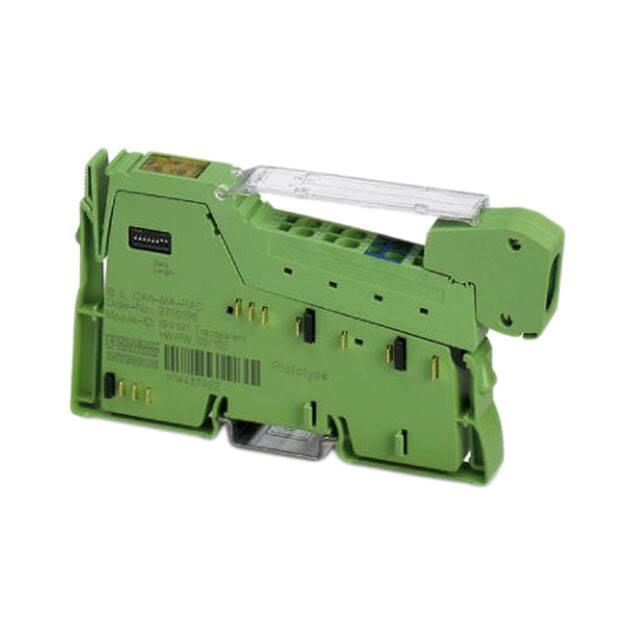
IB IL CAN-MA-XC-PAC
Inline CAN master, extreme conditions version,
for connecting a CAN bus system
Data sheet
8355_en_01
1
© PHOENIX CONTACT 2015-06-29
Description
The terminal is designed for use within an Inline station.
Local bus features
It can be used to integrate a lower-level CAN bus system
into the Inline station and thus in the bus system used.
–
–
Within the Inline station, the terminal acts as a CAN master
for the lower-level CAN system.
Thanks to special engineering measures and tests, the terminal can be used under extreme ambient conditions.
Transmission speed of 500 kbps in local bus
Maximum data width 2 x 64 bytes
(= 128 bytes = 64 words);
Data channel width: 126 bytes;
Command/status word width: 2 bytes
General features
CAN features
–
–
–
–
–
–
–
–
–
–
CAN master
Protocol: Transparent mode
Transmission speed: 1 Mbps, maximum
Smallest data type: 1 byte
Diagnostic and error messages are exchanged via the
status word
–
Serial interface with plugged-in memory stick for saving
configuration data
DIP switch for setting the data width
Diagnostic and status indicators
Can be used under extreme ambient conditions
Extended temperature range of -40°C ... +70°C
(see “Tested successfully: use under extreme ambient
conditions”)
Painted PCBs
This data sheet is only valid in association with the IL SYS INST UM E user manual.
Make sure you always use the latest documentation.
It can be downloaded from the product at phoenixcontact.net/products.
�IB IL CAN-MA-XC-PAC
2
Table of contents
1
Description .............................................................................................................................. 1
2
Table of contents ..................................................................................................................... 2
3
Ordering data .......................................................................................................................... 3
4
Technical data ......................................................................................................................... 3
5
Additional tables ...................................................................................................................... 5
6
Tested successfully: Use under extreme ambient conditions .................................................. 6
7
Internal circuit diagram ............................................................................................................ 7
8
Terminal point assignment....................................................................................................... 8
9
Connection examples ............................................................................................................ 10
10
Connection notes .................................................................................................................. 10
11
Local status and diagnostic indicators ................................................................................... 11
12
Setting the data width on the local bus with DIP switches 1 and 2 ......................................... 12
13
Interface with memory stick (Flash memory) ......................................................................... 12
14
Configuration ......................................................................................................................... 13
14.1 Connection between Inline terminal and PC ............................................................................. 13
14.2 “IL CAN MA Configurator” configuration and download tool .......................................................... 14
14.3 Possible parameters ........................................................................................................... 14
14.4 Connector pin assignment for configuration .............................................................................. 15
15
Transparent mode ................................................................................................................. 16
16
Transmission mode ............................................................................................................... 16
17
Input and output data............................................................................................................. 17
18
Output data of the bus coupler/the controller ......................................................................... 18
18.1 SUPI A output data (INCA; bus coupler/controller data direction -> low-level CAN bus) ....................... 18
18.2 SUPI B output data (INCA; bus coupler/controller data direction -> lower-level CAN bus) .................... 19
19
Input data of the bus coupler/the controller............................................................................ 21
19.1 SUPI A input data (CAIN; lower-level CAN data direction -> bus coupler/controller) ............................ 21
19.2 SUPI B input data (CAIN; lower-level CAN bus data direction-> bus/bus coupler) .............................. 22
20
Function block ....................................................................................................................... 25
8355_en_01
PHOENIX CONTACT
2
�IB IL CAN-MA-XC-PAC
3
Ordering data
Description
Type
Order No.
Pcs./Pkt.
Inline function terminal, version for extreme conditions, for connecting a
CAN bus system, complete with accessories (connector plug and labeling
field)
IB IL CAN-MA-XC-PAC
2701160
1
Accessories
Type
Order No.
Pcs./Pkt.
Inline shield connector (Connector/Adapter)
IB IL SCN 6-SHIELD-TWIN
2740245
5
Multi-functional memory blockfor the INTERFACE systemf for easy storage and backup of the configuration.
IFS-CONFSTICK
2986122
1
Inline shield connector (Connector/Adapter)
IB IL SCN-6 SHIELD
2726353
5
Configuration cable for IB IL CAN-MA-PAC
IB IL CAN-MA CONF-CAB
2700620
1
Documentation
Type
Order No.
Pcs./Pkt.
User manual, English, Automation terminals of the Inline product range
IL SYS INST UM E
-
-
Quick start guide, English, Starting up the IB IL CAN-MA-PAC terminal
UM QS EN IB IL CAN-MA-PAC
-
-
4
Technical data
Dimensions (nominal sizes in mm)
136,8
71,5
119,8
Width
12.2 mm
Height
136.8 mm
Depth
71.5 mm
General data
Color
green
Weight
75 g
Operating mode
Process data mode with up to 64 words
Mounting type
DIN rail
Ambient temperature (operation)
-25 °C ... 55 °C (Standard)
-40 °C ... 70 °C (Extended, see section “Tested successfully: use under extreme
ambient conditions” in the data sheet.)
Ambient temperature (storage/transport)
-40 °C ... 85 °C
Permissible humidity (operation)
10 % ... 95 % (according to DIN EN 61131-2)
Permissible humidity (storage/transport)
10 % ... 95 % (according to DIN EN 61131-2)
Air pressure (operation)
70 kPa ... 106 kPa (up to 3000 m above sea level)
Air pressure (storage/transport)
70 kPa ... 106 kPa (up to 3000 m above sea level)
8355_en_01
PHOENIX CONTACT
3
�IB IL CAN-MA-XC-PAC
General data
Degree of protection
IP20
Protection class
III, IEC 61140, EN 61140, VDE 0140-1
Pollution degree
2
Connection data
Designation
Inline connector
Connection method
Spring-cage connection
Conductor cross section solid / stranded
0.08 mm² ... 1.5 mm² / 0.08 mm² ... 1.5 mm²
Conductor cross section [AWG]
28 ... 16
Stripping length
8 mm
Connection data for UL approvals
Designation
Inline connector
Connection method
Spring-cage connection
Conductor cross section solid / stranded
0.2 mm² ... 1.5 mm² / 0.2 mm² ... 1.5 mm²
Conductor cross section [AWG]
24 ... 16
Stripping length
8 mm
Interface Inline local bus
Connection method
Inline data jumper
Transmission speed
500 kBit/s
Interface CAN bus
No. of channels
1
Connection method
Inline shield connector
Protocols supported
CAN
Power consumption
Main circuit supply UM
24 V DC (via voltage jumper)
Current consumption from UM
typ. 10 mA
max. 12 mA
Communications power UL
7.5 V (via voltage jumper)
Current consumption from UL
typ. 110 mA
max. 115 mA
Power consumption
typ. 1.06 W
Power loss
0.9 W (Module)
Programming Data SUPI A
ID code (hex)
BF
ID code (dec.)
191
Length code (hex)
20
Length code (dec.)
32
Process data channel
64 Byte (Default; configurable)
Input address area
max. 64 Byte
Output address area
max. 64 Byte
Parameter channel (PCP)
0 Byte
Register length
max. 64 Byte
8355_en_01
PHOENIX CONTACT
4
�IB IL CAN-MA-XC-PAC
Programming Data SUPI B
ID code (hex)
BF
ID code (dec.)
191
Length code (hex)
20
Length code (dec.)
32
Process data channel
64 Byte (Default; configurable)
Input address area
max. 64 Byte
Output address area
max. 64 Byte
Parameter channel (PCP)
0 Byte
Register length
max. 64 Byte
In PC Worx, select the device description that matches the connected configuration.
Configuration and parameter data in a PROFIBUS system
Required parameter data
1 Byte
Need for configuration data
5 Byte
Electrical isolation/isolation of the voltage areas
Test section
Test voltage
24 V supply UM, bus, logic/CAN interface
500 V AC, 50 Hz, 1 min
24 V supply UM, bus, logic/functional earth ground
500 V AC, 50 Hz, 1 min
CAN interface/functional earth ground
500 V AC, 50 Hz, 1 min
Error messages to the higher level control or computer system
CAN bus voltage faulty
Bus stop
Approvals
For the latest approvals, please visit phoenixcontact.net/products.
5
Additional tables
Limitation of simultaneity, derating
No limitation of simultaneity, no derating
8355_en_01
PHOENIX CONTACT
5
�IB IL CAN-MA-XC-PAC
6
Tested successfully: Use under extreme ambient conditions
XC terminals have been tested successfully over 250 temperature change cycles in accordance with IEC 61131-2 in
the range from -40°C to +70°C.
The following conditions were observed:
– The Inline devices for all connecting cables were connected with a minimum conductor cross section of
0.5 mm²
– The Inline station was assembled on a wall-mounted
horizontal DIN rail
– Fans were used to ensure continuous movement of air
in the control cabinet
– The Inline station was not exposed to vibration or shock
– The Inline station was operated with a maximum of
24.5 V (ensured by using regulated power supply units)
3 h + 30 min
t1
Tmax + 2 K
(3 + 0,6) K/min
Tmin + 3 K
3 h + 30 min
t1
1
Figure 1
Temperature change cycle
Temperature in the control cabinet/ambient
temperature
Cycle
WARNING:
The terminal is not approved for use in potentially explosive areas.
The terminal is not approved for use in safety
technology.
8355_en_01
PHOENIX CONTACT
6
�IB IL CAN-MA-XC-PAC
7
Internal circuit diagram
Key:
SUPI 4
Local bus
SUPI4
(2 x)
UL+
UANA
UL-
Protocol chip
(Bus logic including voltage conditioning)
Diagnostic and status indicators
µC
Microprocessor
3,3 V
DIP switch
DIP
µP
S-PORT
DIP
Optocoupler
CAN bus logic
CAN
CAN
5V
S-PORT (memory stick)
S-PORT
24 V
DC/DC converter without electrical isolation
+24 V (US)
Explanation for other used symbols has been
provided in the IL SYS INST UM E user manual.
+24 V (UM)
Figure 2
8355_en_01
Internal wiring of the terminal points
PHOENIX CONTACT
7
�IB IL CAN-MA-XC-PAC
8
Terminal point assignment
NOTE: Malfunction with wrong connector
The connector supplied with the module has
been designed for normal operation. In this
connector, terminal points 1.3 and 2.3 are
jumpered internally. Terminal point 1.3 is not
connected with the associated contact pin of
the device. This terminal point is only available to connect the ground cable of a second
CAN cable.
You need an IB IL SCN-6 SHIELD shield plug
for configuration. A bridge is not provided in
this case, all terminal points are connected to
the contact pins of the device. Use an external
bridge between terminal points 1.3 and 2.3 to
set the configuration mode.
These terminal points with the jumper from 1.3
and 2.3 are marked in blue on the connector
supplied upon delivery.
8355_en_01
Terminal Signal
point
1.1
CAN_H
1.2
1.3
CAN_H
GNDBUS
2.1
CAN_L
2.2
2.3
1.4, 2.4
CAN_L
GNDBUS
Shield
1.1 2.1
2.1
Terminal Signal
point
1.2
1.2 2.2
2.2
1.1
CAN_H
1.3
1.3 2.3
2.3
1.2
1.3
2.1
CAN_H
CAN_L
2.2
2.3
1.4, 2.4
CAN_L
GNDBUS
Shield
Terminal point assignment
Assignment
Color in
the CAN
cable
CAN high; connection White
of termination resistor
CAN High
White
CAN ground
black
Bridge in connector to
2.3, no connection to
associated contact pin
of the device
CAN low; connection blue
of termination resistor
CAN Low
blue
CAN ground
black
Shield connection
-
Connector assignment: normal operation, replacement item IB IL SCN-6 SHIELD or IB IL SCN 6-SHIELDTWIN
1.1
1.4 2.4
Figure 3
Connector assignment: normal operation, connector
included in the scope of delivery
Assignment
Color in
the CAN
cable
CAN high; connection White
of termination resistor
CAN High
White
Must remain open!
CAN low; connection blue
of termination resistor
CAN Low
blue
CAN ground
black
Shield connection
-
PHOENIX CONTACT
8
�IB IL CAN-MA-XC-PAC
Connector pin assignment: Connector for configuration
The connector for configuration is part of the configuration
cable (see “ordering data”).
If you assemble the configuration cable yourself, please use
the IB IL SCN-6 SHIELD connector.
Terminal Signal
point
1.1
CAN_H
1.2
1.3
CAN_H
Mode
2.1
CAN_L
2.2
2.3
1.4, 2.4
CAN_L
GNDBUS
Shield
Assignment
Color in
the CAN
cable
CAN high; connection White
of termination resistor
CAN High
White
Configuration mode, black
when the bridge is
connected to GNDBUS
CAN low; connection blue
of termination resistor
CAN Low
blue
CAN ground
black
Shield connection
-
Insert a bridge between terminal points 1.3 and 2.3 of the IB
IL SCN-6 SHIELD connector to switch to configuration
mode. You may also use the configuration cable instead
(see “ordering data”).
8355_en_01
PHOENIX CONTACT
9
�IB IL CAN-MA-XC-PAC
9
Connection examples
ILC
IL I/O
FR
UL FF
US
UM
MRESET
E
RDY FAIL
BSA PF
Q1 Q2
Q3 Q4
I1 I2
I3 I4
I5 I6
I7 I8
CAN-MA
D1
D2
CAN
MD
TR
STOP
RUN / PROG
X1
RESET
CAN
CAN
PRG
LNK
ACT
LNK
ACT
Figure 5
X2.1
CAN master in the center of a CAN bus when
using the original connector
X2.2
CAN
R = 124 �
Figure 4
CAN master within an Inline station
Key:
ILC
IL I/O
CAN-MA
CAN
Inline controller as head of the Inline station
(could also be a bus coupler)
Inline terminals corresponding to your application
CAN master
IB IL CAN-MA-PAC
Connection to the low-level CAN bus
CAN
Figure 6
NOTE: malfunction when incorrectly
wired
If you use a replacement item instead of the
original connector, make sure that terminal
point 1.3 cannot be used!
10
CAN master at the end of a CAN bus
(R = 124 Ω termination resistor)
Connection notes
Observe the DR303-1 CANopen specification when installing the CAN bus.
If you use the CAN master in the middle of the
CAN bus, use the IB IL SCN 6-SHIELD-TWIN
as replacement item.
Connect the GND of both CAN cables to terminal point 2.3 an.
For connection to a CAN cable, you can use
IB IL SCN-6 SHIELD or IB IL SCN 6-SHIELDTWIN as replacement item.
Connect the GND of the CAN cables to terminal point 2.3.
8355_en_01
PHOENIX CONTACT
10
�IB IL CAN-MA-XC-PAC
11
Local status and diagnostic indicators
Function identification
Orange
D1
D2
CAN
MD
TR
Figure 7
Local status and diagnostic indicators
Designa- Color
tion
D1, D2
Green
CAN
Red/green
Green ON
Green, single-flash
Red ON
Red, single-flash
OFF
MD
Red/green
Green ON
Green
flashing
Red ON
Red flashing
OFF
TR
Green
ON
OFF
Meaning
Diagnostics (bus and logic voltage)
See IB IL SYS INST UM user
manual
Data transmission
Data transmission via the CAN
bus
Data transmission stopped (with a
command)
Bus OFF (CAN master has no connection to the bus)
At least one error counter has
reached the warning level.
Supply voltage is missing or terminal in reset
Module diagnostics
Device ready to operate
Configuration mode
(Bridge inserted between terminal
points 1.3 and 2.3)
Peripheral fault (e. g., faulty power
supply)
No memory stick plugged or no
valid configuration on the memory
stick
Supply voltage is missing or terminal in reset
PCP (not supported in transparent
mode)
PCP active
PCP not active
Key:
Single flash
Flashing
8355_en_01
20 % on, 80 % off
50 % on, 50 % off
PHOENIX CONTACT
11
�IB IL CAN-MA-XC-PAC
12
Setting the data width on the local
bus with DIP switches 1 and 2
If you use the CAN master in a PROFIBUS
station (e. g., with the IL PB BK DI8 DO4-PAC
bus coupler or IL PB BK DI8 DO4/EF-PAC),
please set a data width greater that 0 on the
SUPI B.
The expansion of the CAN system may vary. The maximum
possible data width is set on the CAN master (default). The
data width may be reduced to optimize the time response.
If you disregard this information the “Less
modules available than have been configured” error message will appear and you cannot operate the module.
The data width is set with switches 1 and 2 of an 8-pos. DIP
switch located on the left side of the housing.
The switch position is read after power up. The data width
cannot be changed during operation.
Set the data width before you install the terminal since the switch can no longer be accessed when the terminal is installed.
13
Interface with memory stick (Flash
memory)
1
1
2
3
4
5
6
7
8
O
N
Data
Length
1
2
3
4
5
6
7
8
O
N
Data
Length
Figure 9
Interface with memory stick (1)
There is an interface with a plugged-in memory stick on the
inclined part. Configuration data is stored on the memory
stick.
Figure 8
DIP switch for setting the data width
When you replace a device you can transfer the configuration by inserting the memory stick into the new device.
Data width (in bytes) depending on the DIP switches:
DIP switch (2,
1)
PD SUPI A
PD SUPI B
PD total
00
01
10
11 (Default)
32
0
32
64
0
64
64
32
96
64
64
128
Key:
PD SUPI x
SUPI
PD total
Process data width on microprocessor x
Protocol chip
Total process data width (incl. 2 bytes each
for the configuration and status word)
DIP switches 8 to 3 are reserved and are not evaluated.
8355_en_01
PHOENIX CONTACT
12
�IB IL CAN-MA-XC-PAC
14
Configuration
You only need to configure the Inline CAN
master when you do not use the default setting. For default setting, see section “Possible
parameters”.
For configuration, connect the PC to the CAN master. To do
this, use the USB CAN adapter and the configuration cable
(see “ordering data”) or assemble a connecting cable with
the IB IL SCN-6 SHIELD connector (see “Connector assignment for configuration”).
Please make sure that the jumper between terminal points
1.3 and 2.3 is installed for configuration.
Configure the CAN master and the low-level CAN system as
“local configuration” via the CAN interface.
R = 124 �
Configuration data is stored on the memory stick.
NOTE: no CAN communication in the
event of invalid configuration data on the
memory stick!
1.3 -2.3
USB
No CAN communication is possible if the
memory stick is empty or not inserted, or if
there is no valid configuration data on the
memory stick.
USB-CAN
IB IL CAN-MA CONF-CAB
Make sure that the memory stick is plugged in
with a valid configuration.
A valid configuration is on the memory stick on
delivery (default setting: see section “Possible
parameters”).
Figure 10
USB-CAN adapter and configuration cable
Key:
14.1
Connection between Inline terminal and PC
Remove the original connector for configuration.
NOTE: Malfunction with wrong connector
Do not use the connector supplied upon delivery.
For configuration, you need either the configuration cable (see “ordering data”) or a selfassembled cable with IB IL SCN-6 SHIELD
shield plug.
USB
USB connector for connection to
the PC
USB-CAN
USB CAN adapter
USB-to-CAN compact
(Company IXXAT)
IB IL CAN-MA CONF- D-SUB Inline configuration cable
CAB
(see Ordering Data)
1.3 - 2.3
Bridge
NOTE: malfunction with additional CAN device
For configuration, there may only be a 1:1
connection between PC and CAN master.
Make sure that no other CAN device is connected.
If you switch between configuration and normal operation, reset the voltage every time after you have changed the connector. The
changed mode will only be detected after
power up.
The MD LED is flashing when the terminal is
in configuration mode.
8355_en_01
PHOENIX CONTACT
13
�IB IL CAN-MA-XC-PAC
14.2
“IL CAN MA Configurator” configuration and
download tool
14.3
You can configure the following parameters:
The “IL CAN MA Configurator” is available as configuration
and download tool for configuration and downloading the
configuration onto the CAN master.
The tool can be downloaded free of charge online at phoenixcontact.net/products, under the item IB IL CAN-MAPAC.
The values in bold show the default setting.
When you use this configuration, you do not
need to configure the Inline CAN master.
-
Install this tool, configure the terminal and therefore the CAN
bus, and download the configuration to the memory stick.
NOTE: prevent accidental overwriting
When downloading the project after the configuration process, the configuration is transmitted immediately to the terminal/memory
stick. You will not be requested whether you
want to actually overwrite the previous project.
-
-
Save the old project before downloading it, if
required.
An example of starting up the CAN bus can be
found in the UM QS DE IB IL CAN-MA-PAC
quick start guide.
-
-
8355_en_01
Possible parameters
Activate transparent mode
(see also "Transparent Mode"; further modes can be
selected later)
Activate evaluation of the command word bits
PI Exchange Stop
CAN Stop
Transmission mode
Unconfirmed transmission
Confirmed transmission
Baud rate in the CAN bus
1000 kbps
00hex
800 kbps
01hex
500 kbps
02hex
250 kbps
03hex
125 kbps
04hex
100 kbps
05hex
50 kbps
06hex
20 kbps
07hex
10 kbps
08hex
Filter for 11-bit identifier
All messages received
Use filter list
No messages received
Filter for 29-bit identifier
All messages received
Use filter list
No messages received
PHOENIX CONTACT
14
�IB IL CAN-MA-XC-PAC
14.4
Connector pin assignment for configuration
If you do not use the pre-assembled configuration cable, assemble the cable for connecting the CAN master to the PC
according to the interface assignment.
IB IL SCN-6 SHIELD assignment
See "Terminal point assignment, connector assignment:
Connector for configuration".
D-SUB connection assignment
D-SUB
1
2
3
4
5
6
7
8
9
Signal
Assignment
Color in the
CAN cable
Not used
CAN_L
CAN Low
blue
CAN_GND
CAN ground black
Not used
(CAN_SHLD) Optional: CAN
shield
(GND)
Optional:
Ground
CAN_H
CAN High
White
Not used
(CAN_V+)
Optional: CAN
external, positive supply
D-SUB
e
Inline
nilnI
R = 124 �
5
1
9
6
CAN_H
CAN_L
CAN_GND
7
2
3
White
Blue
Black
Solder side
CAN_H
CAN_L
CAN_H
CAN_L
Mode
GNDBUS
Shield
Shield
1.1
2.1
1.2
2.2
1.3
2.3
1.1
1.1 2.1
2.1
1.2
1.2 2.2
2.2
1.3
1.3 2.3
2.3
1.4 2.4
1.4
2.4
9-pos. D-SUB
socket
Figure 11
8355_en_01
Connector pin assignment of the D-SUB socket and the Inline connector for the configuration cable
PHOENIX CONTACT
15
�IB IL CAN-MA-XC-PAC
15
Transparent mode
The transparent mode allows direct access to Layer 2 of the
ISO/OSI reference model. The user establishes communication within his application over a separate protocol. All
outgoing and incoming CAN messages are transmitted with
the help of a simple serial protocol within the process data
channel. The higher customer-specific protocol actually
takes place within the controller.
Protocol functions in the process data channel:
– Initializing the CAN controller
– Starting and stopping the CAN controller
– Transmitting a CAN message (with handshake mechanism)
– Configuring a filter for received messages (filtering over
an identifier)
– Reporting the status of the CAN controller (e.g., Bus
Off)
16
Transmission mode
You select the active transmission mode when you configure the CAN master.
– Unconfirmed transmission
With unconfirmed transmission, new data is transmitted
with every bus cycle. A maximum data throughput is
achieved with this mode. However, data may be lost
without the transmitter or receiver noticing it. When using unconfirmed transmission, implement data integrity
into a higher protocol layer (separately from the Inline
CAN master).
–
Confirmed transmission
The transmitter keeps transmitting the data until it receives a confirmation from the receiver. Advantage: secured data transmission. Disadvantage: low data
throughput.
Access to layer 2 is supported via the handling components
for PC Worx. Handling components for Step 7 are planned.
8355_en_01
PHOENIX CONTACT
16
�IB IL CAN-MA-XC-PAC
17
Input and output data
Key for the following sections:
ILC
CAN message
CAN data packet
n data bytes + CAN-ID (2 bytes with
11-bit CAN message, 4 bytes with 4
bytes with 29 bits CAN message)
CAN message + message length
(LEN; 4 bits) + command code (CMD;
4 bits)
IL I/O
FR
UL FF
US
UM
MRESET
E
RDY FAIL
BSA PF
Q1 Q2
Q3 Q4
I1 I2
I3 I4
I5 I6
I7 I8
CAN-MA
D1
D2
CAN
MD
TR
STOP
RUN / PROG
X1
RESET
PRG
LNK
ACT
LNK
ACT
X2.1
Example of a CAN message and a CAN data packet with 11bit CAN message:
Byte
x
CAN mes- Data
sage
byte n
CAN data Data
packet
byte n
CAIN
INCA
...
...
...
7
Data
byte 0
Data
byte 0
6
5
RTR, CAN-ID
4
RTR, CAN-ID
LEN/
CMD
Short designation for the data direction lowerlevel CAN -> bus coupler/controller
Data that the CAN master receives from the
lower-level CAN bus and transmits to the bus
coupler/controller (input data of the controller).
A CAIN data record consists of the CAIN data of
SUPI A and CAIN data of SUPI B. All data is valid
and will be processed only when the data record
is consistent.
Short designation for the data direction bus coupler/controller -> CAN
Data that the CAN master receives from the bus
coupler/controller and sends to the lower-level
CAN bus (output data of the controller).
An INCA data record consists of the INCA data of
SUPIA and INCA data of the SUPI B. All data is
valid and will be processed by the Inline CAN
master only when the data record is consistent.
8355_en_01
X2.2
CAIN
CAN
INCA
Figure 12
Structure and data flow
Key:
ILC
IL I/O
CAN-MA
CAN
Inline controller as head of the Inline station
(could also be a bus coupler)
Inline terminals corresponding to your application
CAN master
IB IL CAN-MA-PAC
Lower-level CAN bus
PHOENIX CONTACT
17
�IB IL CAN-MA-XC-PAC
18
Output data of the bus coupler/the controller
18.1
SUPI A output data (INCA; bus coupler/controller data direction -> low-level CAN bus)
Command word
Word
Byte
Bit
Assig
nmen
t
OUT0
1
7
0
6
0
5
0
4
0
0
3
0
2
0
1
0
0
0
7
0
6
0
5
0
4
0
3
0
2
0
1
0
CAN PI Ex
Stop Stop
Byte 0, Bit 1: CAN Stop
0
Start the CAN controller
1
Stop the CAN controller
Byte 0, Bit 0: PI Ex Stop (PI Exchange Stop)
0
CAN messages are sent and received
1
CAN messages are neither sent nor received
The Inline CAN master only responds to the
Stop and PI Ex Stop control bits when the bits
have been activated with the configuration parameters.
Word
Byte
Bit
Assig
nmen
t
OUT1
3
7
6
5
4
CAIN Ack
(ID of last
CAN data packet)
2
3
2
1
0
INCA ID
(Identification of the
CAN data packet)
Byte 3, bit 7 ... 4: CAIN Ack
For confirmed transmission, the ID of the CAN data packet
received last will be returned to the transmitter as an acknowledgment. Only when the transmitter got the ID back will
the next CAN data packet be sent.
Byte 3, bit 3 ... O: INCA ID
Every CAN data packet to be sent is to be given a consecutive count value for identification.
Value range:
8355_en_01
7
6
5
4
Number of SUPI B CAN
data packets
3
2
1
0
Number of SUPI A CAN
data packets
Byte 2, bit 7 ... 4: Number of SUPI B CAN data packets
Number of CAN data packets received from the local bus and
transmitted over the lower-level CAN bus in the process data
channel of SUPI B.
Byte 2, bit 3 ... 0: number of SUPI A CAN data packets
Number of CAN data packets received from the local bus and
transmitted via the lower-level CAN bus in the process data
channel of SUPI A.
0hex ... Ehex
PHOENIX CONTACT
18
�IB IL CAN-MA-XC-PAC
18.2
SUPI B output data (INCA; bus coupler/controller data direction -> lower-level CAN bus)
Command word
Word
Byte
Bit
Assig
nmen
t
OUT0
1
7
6
5
4
3
2
OUT data byte 0
(Output data)
8355_en_01
0
1
0
7
6
5
4
CAIN Ack
(ID of last
CAN data packet)
3
2
1
0
INCA ID
(Identification of the
CAN data packet)
Byte 0, bit 7 ... 0: CAIN Ack
For confirmed transmission, the ID of the CAN data packet
received last will be returned to the transmitter as an acknowledgment. Only when the transmitter got the ID back will
the next CAN data packet be sent.
Byte 0, bit 3 ... 0: INCA ID
Every CAN data packet to be sent is to be given a consecutive count value for identification.
Value range:
0hex ... Ehex
The values for CAIN Ack and INCA ID must match the values
on SUPI A.
PHOENIX CONTACT
19
�IB IL CAN-MA-XC-PAC
CAN data packet
Example: 11-bit CAN message and 8 byte data
The first CAN data packet in SUPI A is shown.
A CAN data packet in SUPI B starts in the next
free byte (byte 1).
In the case of a CAN bus with 29-bit CAN
message, 2 further bytes are required for the
CAN ID.
Word
Byte
Bit
Assig
nmen
t
OUT2
5
7
6
5
4
3
2
CAN ID bit 7 ... 0
(CAN identifier, lower byte)
4
1
8355_en_01
6
5
4
LEN
(Length of the CAN message)
3
2
1
0
CMD
(Command code)
OUT3
7
6
5
7
4
3
2
OUT data byte 0
(Output data)
6
1
OUT4
OUT5
OUT6
OUT7
7
Byte 4, bit 7 ... 4: LEN (Length of the CAN message)
Indicates the length of the CAN message in bytes, consisting
of CAN ID (2 bytes) + n data bytes
Byte 4, bit 3 ... 0: CMD (command code)
0
11-bit CAN message
1
29-bit CAN message
Word
Byte
Bit
Assig
nmen
t
0
0
7
RTR
6
0
5
0
4
0
3
2
1
0
CAN ID bit 11 ... 9
(CAN identifier, higher bits)
Byte 8, Bit 7: RTR (Remote Transmission Request)
0
No RTR message
1
RTR message
Byte 9: OUT data byte 2
Byte 11: OUT data byte 4
Byte 13: OUT data byte 6
Byte 15: LEN/CMD of the next CAN data packet
Byte 8: OUT data byte 1
Byte 10: OUT data byte 3
Byte 12: OUT data byte 5
Byte 14: OUT data byte 7
PHOENIX CONTACT
20
�IB IL CAN-MA-XC-PAC
19
Input data of the bus coupler/the controller
19.1
SUPI A input data (CAIN; lower-level CAN data direction -> bus coupler/controller)
Status word
Word
Byte
Bit
Assig
nmen
t
IN0
1
7
0
6
0
5
0
4
0
0
3
CC
Bus
off
2
1
0
CC
CC CAIN
Warn OVR OVR
Byte 1, Bit 3: CC Bus Off
0
CAN master is not in Bus Off
1
CAN master is in Bus Off (can be restarted by
stopping and starting the CAN Stop bit in the
command word. If the CAN Stop bit is not enabled, there will be an automatic restart of the
CAN master with a Bus Off.)
Byte 1, Bit 2: CC Warn
0
CAN master is not in the error warning state
1
CAN master is in the error warning state
Byte 1, Bit 1: CC OVR
0
No CAN controller overrun
1
CAN controller overrun
(A CAN message was not received.)
Byte 1, Bit 0: CAIN OVR
0
No CAIN overrun
1
CAIN overrun
(Not all CAN messages received via CAN could
be entered into the process data buffer of the
bus coupler/controller (data throughput too
low)).
8355_en_01
7
0
6
0
5
0
4
0
3
0
2
0
1
0
CAN PI Ex
Stop Stop
Byte 0, Bit 1: CAN Stop
0
CAN controller is started (sending and receiving
possible)
1
CAN controller is stopped, in Bus Off or in
ERROR Passive State (at least no CAN communication or no transmission possible)
Byte 0, Bit 0: PI Ex Stop (PI Exchange Stop)
0
CAN messages are sent and received
1
CAN messages are neither sent nor received
PHOENIX CONTACT
21
�IB IL CAN-MA-XC-PAC
Word
Byte
Bit
Assig
nmen
t
IN1
3
7
6
5
4
INCA Ack
(ID of last
CAN data packet)
2
3
2
1
0
CAIN ID
(Identification of the
CAN data packet)
Byte 3, bit 7 ... 4: INCA Ack
For confirmed transmission, the ID of the CAN data packet
received last will be returned to the transmitter as an acknowledgment. Only when the transmitter got the ID back will
the next CAN data packet be sent.
Byte 3, bit 3 ... 0: CAIN ID
Every CAN data packet to be sent is to be given a consecutive count value for identification.
3
2
1
0
Number of SUPI A CAN
data packets
Byte 2, bit 7 ... 4: Number of SUPI B CAN data packets
Number of CAN data packets received from the lower-level
CAN bus and to be transmitted to the bus coupler/controller
in the process data channel of SUPI B.
Byte 2, bit 3 ... 0: number of SUPI A CAN data packets
Number of CAN data packets received from the lower-level
CAN bus and to be transmitted to the bus coupler/controller
in the process data channel of SUPI A.
0hex ... Ehex
Value range:
19.2
7
6
5
4
Number of SUPI B CAN
data packets
SUPI B input data (CAIN; lower-level CAN bus data direction-> bus/bus coupler)
Status word
Word
Byte
Bit
Assig
nmen
t
IN0
1
7
0
6
0
5
0
4
0
8355_en_01
0
3
0
2
0
1
0
0
0
7
6
5
4
INCA Ack
(ID of last
CAN data packet)
3
2
1
0
CAIN ID
(Identification of the
CAN data packet)
Byte 0, bit 7 ... 4: CAIN ID
Every CAN data packet to be sent is to be given a consecutive count value for identification.
Value range:
0hex ... Ehex
Byte 0, bit 3 ... 0: INCA Ack
For confirmed transmission, the ID of the CAN data packet
received last will be returned to the transmitter as an acknowledgment. Only when the transmitter got the ID back will
the next CAN data packet be sent.
The values for CAIN Ack and INCA ID must match the values
on SUPI A.
PHOENIX CONTACT
22
�IB IL CAN-MA-XC-PAC
CAN data packet
Example: 11-bit CAN message and 8 byte data
The first CAN data packet in SUPI A is shown.
A CAN data packet in SUPI B starts in the next
free byte (byte 1).
In the case of a CAN bus with 29-bit CAN
message, 2 further bytes are required for the
CAN ID.
Word
Byte
Bit
Assig
nmen
t
IN2
5
7
6
4
5
4
3
2
CAN ID bit 7 ... 0
(CAN identifier, lower byte)
1
0
7
6
5
4
LEN
(Length of the CAN message)
3
2
1
0
CMD
(Command code)
Byte 4, bit 7 ... 4: LEN (Length of the CAN message)
Indicates the length of the CAN message in bytes, consisting
of CAN ID (2 bytes) + n data bytes
Byte 4, bit 3 ... 0: CMD (command code)
0
11-bit CAN message
1
29-bit CAN message
Word
Byte
Bit
Assig
nmen
t
IN3
7
6
5
7
4
3
IN data byte 0
(input data)
6
2
1
0
7
RTR
6
0
5
0
4
0
3
2
1
0
CAN ID bit 11 ... 9
(CAN identifier, higher bits)
Byte 8, Bit 7: RTR (Remote Transmission Request)
0
No RTR message
1
RTR message
IN4
IN5
IN6
IN7
8355_en_01
Byte 9: IN data byte 2
Byte 11: IN data byte 4
Byte 13: IN data byte 6
Byte 15: LEN/CMD of the next CAN data packet
Byte 8: IN data byte 1
Byte 10: IN data byte 3
Byte 12: IN data byte 5
Byte 14: IN data byte 7
PHOENIX CONTACT
23
�IB IL CAN-MA-XC-PAC
Example: 29-bit CAN message and 8-byte data
The first CAN data packet in SUPI A is shown.
A CAN data packet in SUPI B starts in the next
free byte (byte 1).
Word
Byte
Bit
Assig
nmen
t
IN2
5
7
6
4
5
4
3
2
CAN ID bit 7 ... 0
(CAN identifier, lower byte)
1
0
7
6
5
4
LEN
(Length of the CAN message)
3
2
1
0
CMD
(Command code)
Byte 4, bit 7 ... 4: LEN (Length of the CAN message)
Indicates the length of the CAN message in bytes, consisting
of CAN ID (4 bytes) + n data bytes
Byte 4, bit 3 ... 0: CMD (command code)
0
11-bit CAN message
1
29-bit CAN message
Word
Byte
Bit
Assig
nmen
t
Word
Byte
Bit
Assig
nmen
t
IN3
7
6
5
7
4
3
2
CAN ID bit 23 ... 16
1
0
7
6
5
6
4
3
2
CAN ID bit 15 ... 8
1
0
IN4
9
7
6
5
4
3
IN data byte 0
(input data)
8
2
1
0
7
RTR
6
0
5
0
4
3
2
1
0
CAN ID bit 28 ... 24
(CAN identifier, higher bits)
Byte 8, Bit 7: RTR (Remote Transmission Request)
0
No RTR message
1
RTR message
IN5
IN6
IN7
IN8
8355_en_01
Byte 11: IN data byte 2
Byte 13: IN data byte 4
Byte 15: IN data byte 6
Byte 17: LEN/CMD of the next CAN data packet
Byte 10: IN data byte 1
Byte 12: IN data byte 3
Byte 14: IN data byte 5
Byte 16: IN data byte 7
PHOENIX CONTACT
24
�IB IL CAN-MA-XC-PAC
20
Function block
There is a function block available which organizes the data
exchange between the Inline CAN master and all CAN devices connected to it.
This function block can be downloaded at
phoenixcontact.net/products.
For detailed information on how to use the
function block, please refer to the quick start
guide for the Inline CAN master.
8355_en_01
PHOENIX CONTACT GmbH & Co. KG • 32823 Blomberg • Germany
phoenixcontact.com
25
�


 工商网监
湘ICP备2023018690号
工商网监
湘ICP备2023018690号

