https://www.phoenixcontact.com/us/products/2701815
Bus coupler - AXL F BK PN - 2701815
Please be informed that the data shown in this PDF Document is generated from our Online Catalog. Please find the complete data in the user's
documentation. Our General Terms of Use for Downloads are valid
(http://phoenixcontact.com/download)
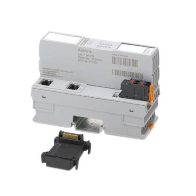
Axioline F bus coupler for PROFINET (including bus base module and connector)
Product Description
The bus coupler is the link between a PROFINET network and the Axioline F system.
Up to 63 Axioline F devices can be connected to an existing Ethernet system using the bus coupler.
Your advantages
Up to 63 additional Axioline devices can be connected
PROFIsafe support
2 RJ45 connections
BootP and DCP
Diagnostic and status indicators
Firmware can be updated
Typical cycle time of the Axioline F local bus is around 10 μs
Safe analog value processing with SAFE AI and other components
Key Commercial Data
Packing unit
1 pc
GTIN
GTIN
4046356845601
Weight per Piece (excluding packing)
240.000 g
Custom tariff number
85389091
Country of origin
Germany
07/04/2020 Page 1 / 14
�https://www.phoenixcontact.com/us/products/2701815
Bus coupler - AXL F BK PN - 2701815
Technical data
Dimensions
Width
45 mm
Height
126.1 mm
Depth
74 mm
Note on dimensions
The depth is valid when a TH 35-7,5 DIN rail is used (according to
EN 60715).
Ambient conditions
Ambient temperature (operation)
-25 °C ... 60 °C (Mounting position: wall mounting on horizontal DIN rail)
-25 °C ... 55 °C (Mounting position: any)
Ambient temperature (storage/transport)
-40 °C ... 85 °C
Permissible humidity (operation)
5 % ... 95 % (non-condensing)
Permissible humidity (storage/transport)
5 % ... 95 % (non-condensing)
Air pressure (operation)
70 kPa ... 106 kPa (up to 3000 m above sea level)
Air pressure (storage/transport)
70 kPa ... 106 kPa (up to 3000 m above sea level)
Degree of protection
IP20
Connection data
Designation
Axioline F connector
Connection method
Push-in connection
Note on the connection method
Please observe the information provided on conductor cross sections in
the “Axioline F: system and installation” user manual.
Conductor cross section solid min.
0.2 mm²
Conductor cross section solid max.
1.5 mm²
Conductor cross section flexible min.
0.2 mm²
Conductor cross section flexible max.
1.5 mm²
Conductor cross section AWG min.
24
Conductor cross section AWG max.
16
Stripping length
8 mm
General
Mounting type
DIN rail mounting
Color
traffic grey A RAL 7042
Net weight
222 g
Note on weight specifications
with connector and bus base module
Mounting type
DIN rail mounting
Mounting position
any
Interfaces
Designation
PROFINET
07/04/2020 Page 2 / 14
�https://www.phoenixcontact.com/us/products/2701815
Bus coupler - AXL F BK PN - 2701815
Technical data
Interfaces
No. of channels
2
Connection method
RJ45 jack
Note on the connection method
Auto negotiation and autocrossing
Transmission speed
100 Mbps (full duplex)
Transmission physics
Ethernet in RJ45 twisted pair
Designation
Axioline F local bus
Connection method
Bus base module
Transmission speed
100 Mbps
Designation
Service
Connection method
Micro USB type B
Network/bus system
Amount of process data
max. 524 Byte (Max. 262 bytes IN - max. 262 bytes OUT)
max. 262 Byte (Input)
max. 262 Byte (Output)
Number of supported devices
max. 63 (per station)
Number of local bus devices that can be connected
max. 63
Power supply for module electronics
Inline potentials
Supply voltage
24 V DC
Supply voltage range
19.2 V DC ... 30 V DC (including all tolerances, including ripple)
19.2 V DC ... 30 V DC (including all tolerances, including ripple)
Axioline potentials
Designation
Communications power UL feed-in (the supply of the Axioline F local bus
UBus is generated from UL)
Supply voltage
24 V DC
Supply voltage range
19.2 V DC ... 30 V DC (including all tolerances, including ripple)
Current consumption
max. 570 mA (with 2 A at UBus for the I/Os and UL = 24 V)
Power consumption
max. 13.7 W (with 2 A load at UBus for the I/Os)
Designation
Axioline F local bus supply (UBus)
Supply voltage
5 V DC (via bus base module)
Power supply unit
2A
Protective circuit
Surge protection of the supply voltage electronic
Polarity reversal protection of the supply voltage electronic
Digital inputs
Connection technology
Push-in connection
07/04/2020 Page 3 / 14
�https://www.phoenixcontact.com/us/products/2701815
Bus coupler - AXL F BK PN - 2701815
Technical data
Standards and Regulations
Mechanical tests
Vibration resistance in acc. with EN 60068-2-6/IEC 60068-2-6 5g
Shock in acc. with EN 60068-2-27/IEC 60068-2-27 30g
Continuous shock according to EN 60068-2-27/IEC 60068-2-27 10g
Protection class
III (IEC 61140, EN 61140, VDE 0140-1)
Environmental Product Compliance
REACh SVHC
Lead 7439-92-1
China RoHS
Environmentally Friendly Use Period = 50 years
For details about hazardous substances go to tab “Downloads”, Category
“Manufacturer's declaration”
Drawings
07/04/2020 Page 4 / 14
�https://www.phoenixcontact.com/us/products/2701815
Bus coupler - AXL F BK PN - 2701815
Connection diagram
07/04/2020 Page 5 / 14
�https://www.phoenixcontact.com/us/products/2701815
Bus coupler - AXL F BK PN - 2701815
Block diagram
Internal wiring of the terminal points
07/04/2020 Page 6 / 14
�https://www.phoenixcontact.com/us/products/2701815
Bus coupler - AXL F BK PN - 2701815
Dimensional drawing
Classifications
eCl@ss
eCl@ss 10.0.1
27242608
eCl@ss 4.0
27240400
eCl@ss 4.1
27240400
eCl@ss 5.0
27242200
eCl@ss 5.1
27242600
eCl@ss 6.0
27242600
eCl@ss 7.0
27242608
eCl@ss 8.0
27242608
eCl@ss 9.0
27242608
ETIM
ETIM 3.0
EC001604
ETIM 4.0
EC001604
07/04/2020 Page 7 / 14
�https://www.phoenixcontact.com/us/products/2701815
Bus coupler - AXL F BK PN - 2701815
Classifications
ETIM
ETIM 5.0
EC001604
ETIM 6.0
EC001604
ETIM 7.0
EC001604
UNSPSC
UNSPSC 6.01
43172015
UNSPSC 7.0901
43201404
UNSPSC 11
39121311
UNSPSC 12.01
39121311
UNSPSC 13.2
32151602
UNSPSC 18.0
32151602
UNSPSC 19.0
32151602
UNSPSC 20.0
32151602
UNSPSC 21.0
32151602
Approvals
Approvals
Approvals
BV / LR / KR / NK / ABS / RINA / PROFINET / PRS / EAC / LR / LR / NK / ABS / PRS / EAC / BV / RINA / PROFINET / PROFINET / KR / ABS / BV /
NK / PRS / RINA / KR / EAC / DNV GL / UL Listed / cUL Listed / UL Listed / cUL Listed / DNV GL / DNV GL / UL Listed / cUL Listed
Ex Approvals
Approval details
BV
LR
http://www.veristar.com/portal/veristarinfo/generalinfo/
approved/approvedProducts/equipmentAndMaterials
36433/B1 BV
http://www.lr.org/en
14-20019
07/04/2020 Page 8 / 14
�https://www.phoenixcontact.com/us/products/2701815
Bus coupler - AXL F BK PN - 2701815
Approvals
KR
http://www.krs.co.kr/eng/main/main.aspx
HMB17372-AC002
NK
http://www.classnk.or.jp/hp/en/
14A006
http://www.eagle.org/eagleExternalPortalWEB/
18-HG1767360-PDA
http://www.rina.org/en
ELE256518XG
Z10813
ABS
RINA
PROFINET
PRS
http://www.prs.pl/
TE/2239/880590/19
EAC
EAC-Zulassung
LR
http://www.lr.org/en
14-20019
LR
http://www.lr.org/en
14-20019
NK
http://www.classnk.or.jp/hp/en/
14A006
http://www.eagle.org/eagleExternalPortalWEB/
18-HG1767360-PDA
ABS
07/04/2020 Page 9 / 14
�https://www.phoenixcontact.com/us/products/2701815
Bus coupler - AXL F BK PN - 2701815
Approvals
PRS
http://www.prs.pl/
TE/2239/880590/19
EAC
EAC-Zulassung
BV
http://www.veristar.com/portal/veristarinfo/generalinfo/
approved/approvedProducts/equipmentAndMaterials
36433/B1 BV
RINA
http://www.rina.org/en
ELE256518XG
PROFINET
Z10813
PROFINET
Z10813
http://www.krs.co.kr/eng/main/main.aspx
HMB17372-AC002
http://www.eagle.org/eagleExternalPortalWEB/
18-HG1767360-PDA
36433/B1 BV
KR
ABS
BV
http://www.veristar.com/portal/veristarinfo/generalinfo/
approved/approvedProducts/equipmentAndMaterials
NK
http://www.classnk.or.jp/hp/en/
14A006
PRS
http://www.prs.pl/
TE/2239/880590/19
07/04/2020 Page 10 / 14
�https://www.phoenixcontact.com/us/products/2701815
Bus coupler - AXL F BK PN - 2701815
Approvals
RINA
http://www.rina.org/en
ELE256518XG
KR
http://www.krs.co.kr/eng/main/main.aspx
HMB17372-AC002
EAC
EAC-Zulassung
DNV GL
https://approvalfinder.dnvgl.com/
TAA00000DF
UL Listed
http://database.ul.com/cgi-bin/XYV/template/LISEXT/1FRAME/index.htm
FILE E 238705
cUL Listed
http://database.ul.com/cgi-bin/XYV/template/LISEXT/1FRAME/index.htm
FILE E 238705
UL Listed
http://database.ul.com/cgi-bin/XYV/template/LISEXT/1FRAME/index.htm
FILE E 238705
cUL Listed
http://database.ul.com/cgi-bin/XYV/template/LISEXT/1FRAME/index.htm
FILE E 238705
DNV GL
https://approvalfinder.dnvgl.com/
TAA00000DF
07/04/2020 Page 11 / 14
�https://www.phoenixcontact.com/us/products/2701815
Bus coupler - AXL F BK PN - 2701815
Approvals
DNV GL
https://approvalfinder.dnvgl.com/
TAA00000DF
UL Listed
http://database.ul.com/cgi-bin/XYV/template/LISEXT/1FRAME/index.htm
FILE E 238705
cUL Listed
http://database.ul.com/cgi-bin/XYV/template/LISEXT/1FRAME/index.htm
FILE E 238705
Accessories
Accessories
Data cable by the meter
Network cable - FL CAT5 HEAVY - 2744814
CAT5-SF/UTP cable (J-02YS(ST)C HP 2 x 2 x 24 AWG), heavy-duty installation cable, 2 x 2 x 0.22 mm², solid conductor,
shielded, outer sheath: 7.8 mm diameter, inner sheath: 5.75 mm ± 0.15 mm diameter
Installation cable - FL CAT5 FLEX - 2744830
By the meter, Installation cable, Ethernet CAT5 (100 Mbps), shielded, PUR halogen-free, water blue RAL 5021, 4-wire
(2x2xAWG26/7; SF/UTP), color single wire: white/orange-orange, white/green-green, cable length: Free entry (1.0 ...
1000.0 m)
Device marking
Insert label - EMT (35X18,7)R - 0801831
Insert label, Roll, white, unlabeled, can be labeled with: THERMOMARK ROLLMASTER 300/600, THERMOMARK X1.2,
THERMOMARK ROLL X1, THERMOMARK ROLL 2.0, THERMOMARK ROLL, mounting type: snapped into marker
carrier, lettering field size: 35 x 18.7 mm, Number of individual labels: 500
07/04/2020 Page 12 / 14
�https://www.phoenixcontact.com/us/products/2701815
Bus coupler - AXL F BK PN - 2701815
Accessories
DIN rail connector
Bus connector - AXL BS BK - 2701422
Axioline F bus base module for housing type BK
Plug
RJ45 connector - FL PLUG RJ45 GR/2 - 2744856
RJ45 connector, shielded, with bend protection sleeve, 2 pieces, gray for straight cables, for assembly on site. For
connections that are not crossed, it is recommended that you use the connector set with gray bend protection sleeve.
RJ45 connector - FL PLUG RJ45 GN/2 - 2744571
RJ45 connector, shielded, with bend protection sleeve, 2 pieces, green for crossed cables, for assembly on site. For
connections that are crossed, it is recommended that the connector set with green bend protection sleeves is used.
Programming cable
Connecting cable - CAB-USB A/MICRO USB B/2,0M - 2701626
Connecting cable, for connecting the controller to a PC for PC Worx and LOGIC+, USB A to micro USB B, 2 m in length.
Software library
07/04/2020 Page 13 / 14
�https://www.phoenixcontact.com/us/products/2701815
Bus coupler - AXL F BK PN - 2701815
Accessories
Function block - SAFE AI - 2400057
Function block library for safety-related analog value acquisition with standard I/O modules. Please contact the safety
hotline (+49 5281 9-462777) before ordering the SAFE AI article.
Terminal marking
Zack marker strip - ZB 20,3 AXL UNPRINTED - 0829579
Zack marker strip for Axioline F (device labeling), in 2 x 20.3 mm pitch, unprinted, 25-section, for individual labeling with
B-STIFT 0.8, X-PEN, or CMS-P1-PLOTTER
Zack Marker strip, flat - ZBF 10/5,8 AXL UNPRINTED - 0829580
Zack Marker strip, flat, Strip, white, unlabeled, can be labeled with: PLOTMARK, CMS-P1-PLOTTER, mounting type:
snap into flat marker groove, for terminal block width: 10.15 mm, lettering field size: 4 of 10.15 x 5 mm and 1 of 5.8 x 5
mm, Number of individual labels: 50
Assembly tool - FL CRIMPTOOL - 2744869
Crimping pliers, for assembling the RJ45 plugs FL PLUG RJ45..., for assembly on site
Phoenix Contact 2020 © - all rights reserved
http://www.phoenixcontact.com
07/04/2020 Page 14 / 14
�