PB IL 24 BK DIO 16/16
PROFIBUS-DP/V1 Bus Coupler Station
With 16 Digital Inputs and 16 Digital Outputs
Data Sheet 643701
07/2003
6 4 3 7 B 0 0 2
Function
This data sheet is only valid in
association with the "Configuring and
Installing the PROFIBUS-DP/V1 bus
coupler for the Inline Product Range"
User Manual, IL PB BK DP/V1 UM E.
A detailed description of the
PROFIBUS-DP/V1 bus coupler
(IL PB BK DP/V1) and the input/
output modules IB IL 24 DI 16 and
IB IL 24 DO 16 can be found in the
relevant data sheets (see "Ordering
Data for Documentation" on page 5).
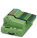
PB IL 24 BK DIO 16/16 is a complete Inline
station, which consists of the components shown
in Figure 1 on page 2.
The PROFIBUS-DP/V1 bus coupler is the link
between PROFIBUS-DP and the Inline
installation system. Inline modules can be
connected in any position to an existing
PROFIBUS-DP system using the
PROFIBUS-DP/V1 bus coupler. In this way, all
the advantages of the installation system created
by these modules can be used on PROFIBUS.
The station can be expanded with additional
Inline modules, AS-i modules or INTERBUS
Loop 2 modules.
643701
1
�PB IL 24 BK DIO 16/16
Station Components
The station consists of the following components
(supplied as standard):
3
4
2
G S D
7
1
1
PROFIBUS-DP/V1 bus coupler
(IL PB BK DP/V1)
–
For the connection of the Inline station to
PROFIBUS-DP
For the provision of the supply voltage for
the connected devices
IB IL 24 DO 16 module for the output of
16 digital output signals
–
2
5
6
3
IB IL 24 DI 16 module for the acquisition of
16 digital input signals
4
End plate
9 x
Place this plate at the end of the Inline
station. The end plate does not have any
electrical function. It protects the station
against ESD pulses and the user against
dangerous contact voltage.
6 4 3 7 B 0 0 1
Figure 1
PB IL 24 BK DIO 16/16 module
5
Connector
6
Labeling fields
7
Disk with device database file (GSD)
The disk contains the device database file
(GSD) required by PROFIBUS and a bitmap
file with an icon of the coupler and
connected Inline modules.
An up-to-date device database file
can be downloaded from the Internet
at www.phoenixcontact.com.
2
643701
�PB IL 24 BK DIO 16/16
Features of the PROFIBUS-DP/V1 Fieldbus Coupler IL PB BK DP/V1
(*) new functions in the IL PB BK-compatible
mode
– A maximum of 63 Inline devices or Loop 2
modules can be connected to
PROFIBUS-DP via the bus coupler. The
PROFIBUS-DP/V1 bus coupler and the
Inline terminals create a station.
– The total of all input and output data of the
connected terminals must not exceed
176 bytes per station in the IL PB BK DP/V1
mode (DIP switch 8 = ON).
(184 bytes in the IL PB BK mode,
DIP switch 8 = OFF)
– DP/V1 for Class 1 and Class 2 masters
– Acyclic communication with, e.g., RS-232
modules also in the process data channel (*)
– I/O module parameterization
– Failsafe values
– Various diagnostic formats
– Acknowledgment of I/O errors from the user
program (*)
– Adaptation of the high byte/low byte format
in 16-channel input and output modules to
the control system format (*)
– The bus coupler can be installed with a data
transmission speed of 9.6 kbps to 12 Mbps.
The bus coupler is automatically set to the
speed specified by the PROFIBUS master.
– The operating voltage of the bus coupler is
24 V DC. The operating temperature range
is 0°C to 55°C (32°F to 131°F).
– Diagnostics is provided locally by LEDs on
the bus coupler, and on the Inline terminals
and Loop 2 modules. All diagnostic
information can be forwarded to the
PROFIBUS master via PROFIBUS.
643701
The intelligent wiring method used in the Inline
terminals and Loop 2 modules enables the
stations to be constructed quickly and easily
because, for example, there is no need for timeconsuming wiring of terminal power supplies. In
the simplest case, it is only necessary for the
power supply units integrated in the
PROFIBUS-DP/V1 bus coupler to be supplied
with 24 V DC. They then generate the operating
voltage required for the PROFIBUS-DP/V1 bus
coupler and the connected Inline terminals.
DIP switch 8 is particularly important, see
IL PB BK DP/V1 (-PAC) data sheet. As default
upon delivery, it is in the "OFF" position. This
means that the device can directly replace the
previous version IL PB BK (Order No.
27 40 05 4) although it also offers some new
functions, see above (*). However, these
functions can only be used on the new devices.
When configuring the device, use the
"PXC_00F0.GSD" GSD and the
"IL PB BK DP/V1 (DIP 8 = OFF)" device entry in
the hardware list.
In the "ON" position, the device offers all the
above functions and has a new PROFIBUS ID
number. It should therefore be configured and
parameterized using the "PXC_06CC.GSD"
GSD and the "IL PB BK DP/V1 (DIP 8 = ON)"
device entry in the hardware list. The stop
response, which was specified by this switch in
the old device, is then set upon
parameterization.
For a detailed description, please
refer to the PROFIBUS-DP/V1 bus
coupler data sheet (see "Ordering
Data for Documentation" on page 5).
3
�PB IL 24 BK DIO 16/16
Function of the IB IL 24 DO 16 Module
Function of the IB IL 24 DI 16 Module
The module is designed for use within an Inline
station. It is used to output digital signals.
The module is designed for use within an Inline
station. It is used to acquire digital input signals.
Features of the IB IL 24 DO 16 Module
Features of the IB IL 24 DI 16 Module
–
Connections for 16 digital actuators
–
Connections for 16 digital sensors
–
Connection of actuators in 2 and 3-wire
technology
–
Connection of sensors in 2 and 3-wire
technology
–
Nominal current of each output: 0.5 A
–
–
Total current of the module: 8 A
Maximum permissible load current per
sensor: 250 mA
–
Short-circuit and overload protected outputs
–
–
Diagnostics and status indicators
Maximum permissible load current from the
module: 4.0 A
–
Diagnostics and status indicators
4
643701
�PB IL 24 BK DIO 16/16
Ordering Data
Description
Order Designation
PROFIBUS-DP/V1 bus coupler station
with 16 digital inputs and 16 digital outputs
(including connectors, labeling fields, end plate
and disk with GSD file)
PB IL 24 BK DIO 16/16
Order No.
27 42 63 8
Ordering Data for Documentation
DB GB IL PB BK DP/V1 (-PAC) 90 13 61 3
Data sheet for Inline module
with 16 digital outputs
DB GB IB IL 24 DO 16 (-PAC) 94 23 25 1
Data sheet for Inline module
with 16 digital inputs
DB GB IB IL 24 DI 16 (-PAC)
94 23 18 3
Configuring and Installing the PROFIBUS-DP/V1
Bus Coupler for the Inline Product Range
IL PB BK DP/V1 UM E
26 98 10 6
CD-ROM with all Inline, INTERBUS Loop 2, and
other data sheets
CD IBS DB ELDOC
27 45 60 6
© Phoenix Contact 07/2003 Technical modifications reserved TNR 90 08 47 1
Data sheet for PROFIBUS-DP/V1 bus coupler
Ensure that you are always working with the latest documentation published.
It can be downloaded at www.phoenixcontact.com.
Phoenix Contact GmbH & Co. KG
Flachsmarktstr. 8
32825 Blomberg
Germany
+ 49 - (0) 52 35 - 3-00
+ 49 - (0) 52 35 - 3-4 12 00
www.phoenixcontact.com
Worldwide Locations:
www.phoenixcontact.com/salesnetwork
5
643701
�
很抱歉,暂时无法提供与“2742638”相匹配的价格&库存,您可以联系我们找货
免费人工找货