IBS ST (ZF) 24 BKM-T
Bus Terminal Module
Data Sheet 5145B
01/2000
5145B000
Terminal Assignment
Terminal Assignment
1
Supply voltage for the module
5
Ground contact of the module
Local Diagnostic and Status Indicators
Des.
R E M O T E IN
U L
R C
B A
E
B u s T e r m in a l
IB S S T 2 4 B K M -T
O rd . N o .: 2 7 5 0 1 5 4
M o d u le Id e n t. : 0 8
L D
R D
R E M O T E O U T
5 1 4 5 B 0 0 1
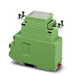
Figure 1 IBS ST 24 BKM-T module
This data sheet is intended to be used
in conjunction with the
IBS SYS PRO UM E User Manual.
Ground the mounting rail. The module
is grounded by snapping it onto the
mounting rail.
5145B
Color Meaning
UL
Green Supply voltage for the
electronics module
RC
Green Incoming remote bus cable
check
BA
Green Remote bus active
E
Red
Error in the ST compact
station (local bus group)
LD
Red
ST compact station (local bus
group) disconnected
RD
Red
Remote bus out disconnected
Bus connection with remote bus
cable: The remote bus cable must be
fitted with the MINI-COMBICON male
connectors supplied with the module.
Plug the connectors into the corresponding
terminal strips (Figure 2), the keying tabs point
towards the front plate of the bus terminal.
REMOTE IN designates the incoming remote
bus, REMOTE OUT the outgoing remote bus.
The module supply voltage US must be provided
via bus terminal contacts 1 (+) and 5 (-), as it is
not supplied via the bus cable.
1
�IBS ST (ZF) 24 BKM-T
Connection Example
Connection of the Supply Voltage and Bus Cables
-
U S
+
IN T E R B U S IN
IN T E R B U S O U T
5 1 4 5 B 0 0 2
Figure 2
2
Connection of the supply voltage and bus cables
5145B
�IBS ST (ZF) 24 BKM-T
Pin Assignment of the Remote Bus Connector
REMOTE IN
Pin
1
Terminal
designation
Signal
Shield
Wire color
2
3
4
5
6
7
8
A
B
C
D
E
DO
DO
DI
DI
COM
Not
used
Shield
Green
Yellow
Pink
Gray
Brown
2
3
4
5
6*
7*
8
F
G
H
J
K*
L*
DO
DO
DI
DI
COM
RBST
Green
Yellow
Pink
Gray
Brown
REMOTE OUT
Pin
1
Terminal
designation
Signal
Shield
Wire color
* Ensure that a jumper is installed
between contacts K and L of the
outgoing remote bus connector, if
the remote out is used.
Shield
Ensure that on the bus terminal
module, the ST cable for the local bus
is connected before the module is
snapped onto the mounting rail, as
the terminal block base and the
module electronics are not pluggable.
Programming Data
ID code
8hex (8dec)
Programmable functions
Length code
0hex
Disconnection of the ST
compact station
Yes
Input address area
0 bytes
Reset of the ST compact
station
Yes
Output address area
0 bytes
Disconnection of the outgoing
remote bus
Yes
Parameter channel (PCP)
0 bytes
Reset of the outgoing remote
bus
Yes
Register length (bus)
0 bytes
Monitoring the incoming
remote bus cable
Yes
5145B
3
�IBS ST (ZF) 24 BKM-T
Technical Data
General
Housing dimensions (width x height x depth)
44 mm x 117 mm x 116 mm
(1.732 in. x 4.606 in. x 4.567 in.)
Permissible operating temperature
From 0°C to 55°C (32°F to 131°F)
Permissible storage temperature
From -20°C to 70°C (-4°F to 158°F)
Degree of protection
IP 20, DIN 40050, IEC 60529
Class of protection
Class 3 VDE 0106, IEC 60536
Humidity (operation)
30% to 75%, no condensation
Humidity (storage)
30% to 95%, no condensation
Air pressure (operation)
From 86 kPa to 108 kPa, 1500 m (4921.26 ft.)
above sea level
Air pressure (storage)
From 66 kPa to 108 kPa, 3500 m (11,482.94 ft.)
above sea level
Electrical isolation
Between incoming and outgoing remote bus
500 V AC test voltage, 50 Hz, 1 min.
Between incoming remote bus and ST local
bus
500 V AC test voltage, 50 Hz, 1 min.
Emitted interference
EN 50081-2, Class A
Preferred installation position
Panel mounting (on a horizontally mounted
DIN rail)
Protective Ground Connection
Via DIN rail
Weight
200 g, typical
Interfaces
INTERBUS
Incoming remote bus
8-pos. MINI-COMBICON connector
Outgoing remote bus
8-pos. MINI-COMBICON connector
ST interface
ST cable
Number of ST modules that can be connected 4 (note the current load)
Supply current for the local bus
4
500 mA
5145B
�IBS ST (ZF) 24 BKM-T
Power Consumption
Communications power
9 V DC
I/O supply voltage US
24 V DC
Current consumption of US
Without ST local bus modules
150 mA at 24 V, typical
Maximum
350 mA at 24 V, typical
Total current consumption of all I/O modules at 500 mA at 9 V, maximum
the ST local bus
I/O Supply Voltage (US)
Nominal value
24 V DC
Permissible ripple
3.6 Vpp within the permissible voltage range
Permissible voltage range (including ripple)
Operation: 20 V DC to 30 V DC
Current consumption of US
Without ST local bus modules
150 mA at 24 V, typical
Maximum
350 mA at 24 V, typical
Permissible total current consumption of all I/O 500 mA at 9 V, maximum
modules from the ST local bus
Polarity reversal of the input voltage and a current of > 2 A can damage the module
electronics as there is no module internal fuse. Therefore, install a 2 A external fuse.
Ordering Data
Meaning
Order Designation
Order No.
BK module (screw-clamp terminals)
IBS ST 24 BKM-T
27 50 15 4
BK module (spring-clamp terminals)
IBS ST ZF 24 BKM-T
27 24 96 0
Replacement shield clamp
IBS RB-SHIELD
27 22 74 2
Replacement remote bus connector set
IBS RB PLSET/MC 1.5/8
27 22 75 5
5145B
5
�© Phoenix Contact 01/2000 TNR 92 70 94 1
IBS ST (ZF) 24 BKM-T
6
5145B
�
很抱歉,暂时无法提供与“2750154”相匹配的价格&库存,您可以联系我们找货
免费人工找货