IBS ST (ZF) 24 BK DIO 8/8/3-T
Bus Terminal Block With Eight Digital Inputs
and Eight Digital Outputs
5 0 6 8 E 0 0 0
Data Sheet 5068F
m
10/2001
Function
po
ne
Via the bus terminal block
IBS ST (ZF) 24 BK DIO 8/8/3-T an
INTERBUS ST compact station can be coupled
to the remote bus. In addition the bus terminal
block has an input/output function.
nt
s.
co
Information which generally applies to
ST modules can be found in the
IBS SYS PRO INST UM E
user manual.
om
Features
Remote bus connections using
copper technology
–
Electrical isolation of the remote bus
segments
–
No electrical isolation of communications power and I/O voltage
–
Connections for eight digital inputs and eight
digital outputs
–
Two FLK interfaces for I/O modules
–
Diagnostic and status indicators
–
Rail mountable
on
l
in
ec
–
Ground the mounting rail. The module
is grounded by snapping it onto the
mounting rail.
5068F
1
�IBS ST (ZF) 24 BK DIO 8/8/3-T
Terminal Assignment
U L
4 9
IN
R C
B
E
B A
7 2
U s 2
5 3
5 2
T E R
U L
6 9
5 6
7 3
7 6
U s 3
5 7
U S
7 7
U s 4
6 1
6 0
IB S S T 2 4 B K D IO
U s 2
8 0
U re c
6 4
8 /8 /3 -T , O rd . N o . 2 7 5 2 4 1 1
U s 3
E 3 /4
U s 4
1 1
1 2
1 3
L D
R D
4
5
6
7
8
9
1 0
IN
1 4
1 5
1 6
m
3
O U T
B u s te r m in a l , 8 d ig ita l In p u t , 8 d ig ita l O u tp u t , 2 4 V D C
, M o d u le Id e n t.: 1 1
1
E 1
2
E 2
3
E 3
4
E 4
5
E 5
6
E 6
7
E 7
8
E 8
9
A 1
1 0
A 2
1 1
A 3
1 2
A 4
1 3
A 5
1 4
A 6
1 5
A 7
1 6
A 8
1 7
2 4 V
1 8
2 4 V
1 9
2 4 V
2 0
2 4 V
2 1
2 4 V
2 2
2 4 V
2 3
2 4 V
2 4
2 4 V
2 5
2 6
2 7
2 8
2 9
3 0
3 1
3 2
3 3
3 4
3 5
3 6
3 7
3 8
3 9
4 0
4 1
4 2
4 3
4 6
4 7
4 8
4 4
4 5
s.
2
nt
1
5 0 6 8 E 0 0 1
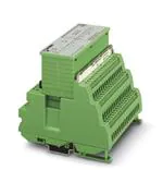
IBS ST 24 BK DIO 8/8/3-T module
on
l
in
ec
om
po
Figure 1
Terminals Assignment
UL
24 V supply voltage of the module
electronics
⊥ (65)
Ground of the supply for the module
electronics
24 V supply voltage of the inputs
US2
⊥ (69)
Ground of the supply for the inputs
24 V supply voltage of outputs O1
US3
through O4
⊥ (73)
Ground of the supply for outputs O1
through O4
24 V supply voltage of outputs O5
US4
through O8
⊥ (77)
Ground of the supply for outputs O5
through O8
Connection of the reconfiguration
UREC
voltage (via external button)
⊥ (80)
Reference ground of the
reconfiguration voltage
I1 - I8
Digital inputs
O1 - O8 Digital outputs
17 - 24 24 V sensor supply voltage
25 - 40 Ground
41 - 48 Functional earth ground
co
6 8
ne
6 5
2
5068F
�IBS ST (ZF) 24 BK DIO 8/8/3-T
Local Diagnostic and Status Indicators
co
s.
on
l
in
ec
om
po
ne
The numbering of the yellow status
indicators corresponds to terminal
block numbering and not to the channel number.
nt
Color Meaning
Green Supply voltage for the module
electronics
E
Red Local bus error
LD
Red Local bus disconnected
RD
Red Remote bus disconnected
RC Green Remote bus connection established
BA Green Remote bus active
US2 Green Supply voltage of the inputs
US3/4 Green Supply voltage of the outputs
E3/4
Red Module error
1 - 16 Yellow Status of the inputs/outputs
m
Des.
UL
5068F
3
�IBS ST (ZF) 24 BK DIO 8/8/3-T
Internal Circuit Diagram
U
U
L
2
S
U
U
3
S
4
S
U
re c
6 5
6 8
6 9
7 2
7 3
7 6
7 7
8 0
4 9
5 2
5 3
5 6
5 7
6 0
6 1
6 4
U
U
L
S
2
U
S
U
3
S
S u p i 3
2 4 V
5 V
co
5 V
IN
re c
4
m
U
9 V
s.
R e m o te
b u s
3
E 3
4
E 4
5
E 5
1 7
2 4 V
1 8
2 4 V
1 9
2 4 V
2 0
2 4 V
2 1
2 4 V
3 3
3 4
3 5
3 6
3 7
6
E 6
7
E 7
8
E 8
9
A 1
po
2
E 2
2 2
2 4 V
2 3
2 4 V
2 4
2 4 V
3 8
3 9
4 0
om
1
E 1
ne
nt
O U T
2 5
4 1
1 0
A 2
1 1
A 3
1 2
A 4
1 3
A 5
1 4
A 6
1 5
A 7
1 6
A 8
2 6
2 7
2 8
2 9
3 0
3 1
3 2
4 2
4 3
4 4
4 5
4 6
4 7
F L K
c o n n e c to r
´o u tp u t´
P in 6
P in 2
4 8
F L
c o
´ in
P
K
n n e c to r
p u t´
in 8
5 0 6 8 F 0 1 0
Internal circuit diagram
in
ec
Figure 2
L o c a l
b u s
IN /O U T
on
l
Note that in Figure 2 one input/output
per group is illustrated.
4
5068F
�IBS ST (ZF) 24 BK DIO 8/8/3-T
Maintaining Electrical Isolation
To prevent eliminating the electrical isolation
between module electronics and I/O devices at
local bus devices with opto-electrically isolated
inputs and outputs, electrically isolate their vol-
tage supplies from the supply voltage of the bus
terminal block. You can achieve safe isolation by
using, for example, several power supply units
(see Figure 3).
m
In c o m in g
re m o te b u s
U S
U S 4
U S
U S
U S U S
2 4 V
9 V
IN
1 ... 8
O U T
1 ... 4
ne
z .B .:
IB S T 2 4 B D I 8 /4
po
M E
O U T
5 ... 8
IN
1 ... 8
om
IB S S T 2 4
B K D IO
8 /8 /3 -T
M E
nt
s.
U L U S 2 U S 3
co
V o lta g e s o u r c e S 2
V o lta g e s o u r c e S 1
S T lo c a l b u s
Figure 3
in
ec
O u tg o in g
re m o te b u s
G r o u n d le v e ls
O U T
1 ... 4
M E
z .B .:
IB S T 2 4
D O 1 6 /3
O U T
5 ... 8
O U T
9 ... 1 2
O U T
1 3 ... 1 6
E le c tr ic a lly
is o la te d
a re a s
5 0 6 8 F 0 0 5
Position of the ground levels
on
l
The supply voltage (UL) of the module
electronics of the bus terminal block,
as well as the module electronics of
the following local bus device is not
electrically isolated from the I/O voltages US2, US3 and US4 of the bus terminal block.
5068F
5
�IBS ST (ZF) 24 BK DIO 8/8/3-T
Internal Wiring of the Terminal Points
IN
U L
Ground the mounting rail. The grounding of terminals 41 to 48 is ensured
by snapping the module onto the
mounting rail.
6 5
6 8
6 9
7 2
7 3
7 6
7 7
8 0
U L
4 9
5 2
U s 2
5 3
5 6
U s 3
5 7
6 0
U s 4
6 1
U re c
6 4
B
T E R
U S
IB S
S T 2 4 B K
D IO
8 /8 /3 -T , O rd . N o . 2 7 5 2 4 1 1
E
U s 2
B A
U s 3
E 3 /4
U s 4
1 1
1 2
1 3
m
R C
L D
R D
5
6
7
8
9
1 0
IN
1 4
1 5
1 6
O U T
B u s te r m in a l , 8 d ig ita l In p u t , 8 d ig ita l O u tp u t , 2 4 V
D C
, M o d u le Id e n t.: 1 1
1
E 1
2
E 2
3
E 3
4
E 4
5
E 5
6
E 6
7
E 7
8
E 8
9
A 1
1 0
A 2
1 1
A 3
1 2
A 4
1 3
A 5
1 4
A 6
1 5
A 7
1 6
A 8
1 7
2 4 V
1 8
2 4 V
1 9
2 4 V
2 0
2 4 V
2 1
2 4 V
2 2
2 4 V
2 3
2 4 V
2 4
2 4 V
2 5
2 6
2 7
2 8
2 9
3 0
3 1
3 2
3 3
3 4
3 5
3 6
3 7
3 8
3 9
4 0
4 1
4 2
4 3
4 6
4 7
4 8
4 4
4 5
5 0 6 8 F 0 0 6
Internal wiring of terminal points
po
Figure 4
co
4
s.
3
nt
2
ne
1
in
ec
Key for Figure 5 and Figure 6:
om
Connecting the Supply Voltages and Potential Jumpering
Internal jumper
Current carrying capacity 6 A,
maximum
on
l
Internal jumper
Current carrying capacity 10 A,
maximum
A potential jumpering of up to a specified maximum current of 6 A or 10 A
can be achieved using the internal
jumpers. If a higher current capacity is
required, external jumpers should be
used.
External jumper
6
5068F
�IBS ST (ZF) 24 BK DIO 8/8/3-T
Connection Example With Five Voltage Sources
IN
B
T E R
U L
S
5 2
2
5 6
S
U S
7 7
U
3
5 7
U
4
S
7 6
7 3
U
5 3
U
3
S
7 2
S
4
U
6 1
6 0
IB S S T 2 4 B K D IO
U
re c
U
re c
IN
8 /8 /3 -T , O rd . N o . 2 7 5 2 4 1 1
U L
Figure 5
U s 3
E 3 /4
7 3
7 6
7 7
4 9
5 2
5 3
5 6
5 7
6 0
6 1
U
L
T E R
B
S
2
IB S S T 2 4 B K D IO
R C
8 0
U s 3
U
U
L
6 5
U
6 4
4
U
re c
6 4
8 /8 /3 -T , O rd . N o . 2 7 5 2 4 1 1
E 3 /4
5 0 6 8 F 0 0 3
re c
IN
U L
T E R
B
5 2
U
6 9
U
L
2
S
6 8
4 9
8 /8 /3 -T , O rd . N o . 2 7 5 2 4 1 1
S
7 2
7 3
7 6
7 7
5 6
5 7
6 0
6 1
2
re c
8 0
U
5 3
U S
IB S S T 2 4 B K D IO
re c
6 4
8 /8 /3 -T , O rd . N o . 2 7 5 2 4 1 1
R C
U s 2
E 3 /4
U s 3
E 3 /4
5 0 6 8 F 0 0 4
on
l
Connection example with two voltage sources
For the module with spring-clamp technology
(left figure in Figure 6) this means that up to a
maximum current carrying capacity of 6 A no additional wiring is needed except for the external
jumpers between the terminal points 56-57 and
60-61.
5068F
S
re c
8 0
in
ec
U s 2
Figure 6
re c
U
U S
ne
7 2
po
U
6 9
om
U L
2
S
6 8
U
IN
U
6 5
U
6 1
6 0
U s 3
4
S
7 7
U
3
S
5 7
IB S S T 2 4 B K D IO
R C
Connection example with five voltage sources
L
U S
U
7 6
7 3
U
5 6
U s 2
Connection Example With two Voltage Sources
U
B
2
5 3
3
S
7 2
S
5 2
T E R
U
6 9
U
L
2
S
6 8
4 9
6 4
R C
U s 2
U
L
6 5
8 0
m
U
L
4 9
U
6 9
s.
U
2
S
6 8
co
U
L
6 5
nt
U
The connection between the
terminal points 69 (-73) and 73 (-77)
is created via the internal jumpers.
You can supply the inputs and outputs
with voltage independently of each
other.
7
�IBS ST (ZF) 24 BK DIO 8/8/3-T
Connection of the Remote bus and the I/O
O u tg o in g
re m o te b u s
6 8
6 9
7 2
7 3
7 6
7 7
U L
4 9
5 2
U s 2
5 3
5 6
U s 3
5 7
6 0
U s 4
6 1
F L K c o n n e c tio n
(o u tp u ts )
8 0
co
6 5
U re c
6 4
F
E
U S
IN
B
T E R
U L
R C
E
B A
U S
IB S S T 2 4 B K D IO
U s 2
8 /8 /3 -T , O rd . N o . 2 7 5 2 4 1 1
U s 3
E 3 /4
U s 4
1 1
1 2
1 3
nt
L D
R D
2
3
4
5
6
7
8
9
1 0
IN
1 4
1 5
B u s te r m in a l , 8 d ig ita l In p u t , 8 d ig ita l O u tp u t , 2 4 V D C
3
E 3
4
E 4
5
E 5
6
E 6
7
E 7
8
E 8
9
A 1
1 7
2 4 V
1 8
2 4 V
1 9
2 4 V
2 0
2 4 V
2 1
2 4 V
2 2
2 4 V
2 3
2 4 V
2 4
2 4 V
2 5
3 3
3 4
3 5
3 6
3 7
1 0
A 2
1 1
A 3
1 2
A 4
1 3
A 5
2 6
2 7
2 8
2 9
3 8
3 9
4 0
4 1
1 4
A 6
1 5
A 7
1 6
A 8
3 0
3 1
3 2
4 6
4 7
4 8
po
2
E 2
om
1
E 1
, M o d u le Id e n t.: 1 1
4 2
4 3
4 4
4 5
5 0 6 8 E 0 0 2
Positions of remote bus and FLK
connections
in
ec
Figure 7
1 6
O U T
ne
1
s.
In c o m in g
re m o te b u s
m
F L K c o n n e c tio n
( in p u ts )
on
l
In addition to the VARIOFACE I/O module, you
can connect up to 4 other ST I/O modules to the
bus terminal block using the ST cable. A maximum local bus current of 500mA must not be exceeded.
You can connect the I/O terminal block and the
optional FLK relays simultaneously. Please note
the maximum permissible current carrying capacity.
8
5068F
�IBS ST (ZF) 24 BK DIO 8/8/3-T
Connection of Sensors/Actuators (Example)
1
E 1
2
E 2
3
E 3
4
E 4
5
E 5
6
E 6
7
E 7
8
E 8
9
A 1
1 0
A 2
1 1
A 3
1 2
A 4
1 3
A 5
1 4
A 6
1 5
A 7
1 6
A 8
1 7
2 4 V
1 8
2 4 V
1 9
2 4 V
2 0
2 4 V
2 1
2 4 V
2 2
2 4 V
2 3
2 4 V
2 4
2 4 V
2 5
2 6
2 7
2 8
2 9
3 0
3 1
3 2
3 3
3 4
3 5
3 6
3 7
3 8
3 9
4 0
4 1
4 2
4 3
4 6
4 7
4 8
4 5
O U T
4 4
m
, M o d u le Id e n t.: 1 1
co
D C
s.
2 4 V
IN
B u s te r m in a l , 8 d ig ita l In p u t , 8 d ig ita l O u tp u t , 2 4 V
Connection of sensors/actuators (example)
on
l
in
ec
om
Connecting VARIOFACE Modules
po
Figure 8
ne
nt
5 0 6 8 F 0 0 7
In p u ts
R e m . O U T
1
A u s g ä n g e
1
E in g ä n g e
R e m . IN
V a r io fa c e I/O
m o d u le
1 4
1 4
O u tp u ts
Figure 9
5068F
5 0 6 8 E 0 0 8
Connection of VARIOFACE modules via FLK connectors
9
�IBS ST (ZF) 24 BK DIO 8/8/3-T
Pin Assignment of the FLK Connectors
2
1
4
3
6
5
8
7
1 0
9
1 2
1 1
1 4
1 3
m
5 0 6 8 1 0 0 6
Pin assignment/bit assignment of inputs/outputs
FLK
pin
Inputs
Terminal
Bit
Signal
Terminal
1
1
7
I1
9
2
2
6
I2
3
3
5
I3
4
4
4
I4
5
5
3
I5
6
6
2
I6
7
7
1
I7
8
8
0
9
co
Figure 10 Pin assignment of the 14-pos. FLK connectors
Outputs
Signal
7
O1
10
6
O2
11
5
O3
12
4
O4
13
3
O5
14
2
O6
15
1
O7
I8
16
0
O8
53
24 V DC (+) US2
57
24 V DC (+) US3
10
69
GND
73
GND
11
53
24 V DC (+) US2
57
24 V DC (+) US3
12
69
GND
73
GND
13
53
24 V DC (+) US2
57
24 V DC (+) US3
69
GND
nt
ne
po
om
in
ec
on
l
14
s.
Bit
-
*
Error message load
relay
* The "Error message load relay" signal is not available on the terminal points.
10
5068F
�IBS ST (ZF) 24 BK DIO 8/8/3-T
Programming Data
0Bhex (11dec)
Length code
01hex
Process data channel
16 bits
Input address area
2 bytes
Output address area
2 bytes
Parameter channel
(PCP)
0 bytes
s.
co
m
ID code
nt
INTERBUS Process Data
Byte 0
Bit
7
Module
Terminal (input
signal)
1
6
5
2
3
Byte 1
4
3
2
1
0
4
5
6
7
8
po
Byte
7
6
5
om
(Byte.Bit)
View
ne
Assignment of the Terminal Points of the Inputs to the INTERBUS Input Data
17 18 19 20 21 22 23 24
Terminal
(ground)
33 34 35 36 37 38 39 40
in
ec
Terminal point
(24 V)
4
3
2
1
0
2
1
0
Not used
Assignment of the Terminal Points of the Outputs to the INTERBUS Output Data
Byte 0
Byte 1
Byte
Bit
7
6
Module
Terminal (output
signal)
9
10 11 12 13 14 15 16
Terminal
(ground)
25 26 27 28 29 30 31 32
Terminal (PE)
41 42 43 44 45 46 47 48
on
l
(Byte.Bit)
View
5068F
5
4
3
2
1
0
7
6
5
4
3
Not used
11
�IBS ST (ZF) 24 BK DIO 8/8/3-T
Technical Data
General Data
118 mm x 116 mm x 117 mm
(4.646 in. x 4.567 in. x 4.606 in.)
Total power dissipation
7.4 W
Permissible operating temperature
0°C to 55°C (32°F to 131 °F)
Permissible storage temperature
-25°C to +70°C (-13°F to 158°F)
Degree of protection
IP 20, DIN 40050, IEC 60529
Class of protection
Class 3 VDE 0106, IEC 60536
Humidity
75% on average, 85% occasionally, no condensation
Air pressure (operation)
From 80 kPa to 106 kPa, 2.000 m (6561.68 ft.)
above sea level
Electrical isolation
Test voltage
ne
nt
s.
co
m
Housing dimensions (width x height x depth)
Incoming remote bus/local bus
Preferred installation position
Protective ground connection
Interfaces
INTERBUS
in
ec
Weight
om
Incoming remote bus/I/O interface
on
l
Incoming remote bus
Outgoing remote bus
500 V AC, 1 min., 50 Hz
500 V AC, 1 min., 50 Hz
po
Incoming/outgoing remote bus
500 V AC, 1 min., 50 Hz
Panel mounting
Via DIN rail
690 g, typical
9-pos. D-SUB male connector
9-pos. D-SUB female connector
Maximum distance to the next remote bus de- 400 m
vice
INTERBUS ST interface
ST cable
Number of ST modules that can be connected Four, maximum (taking current load into account)
Maximum supply current from the bus terminal 500 mA
blcok
Reconfiguration input
Nominal voltage UREC
12
24 V DC
5068F
�IBS ST (ZF) 24 BK DIO 8/8/3-T
Interfaces
Permissible voltage range
-30 V DC to +30 V DC
Voltage range logic 0
-30 V DC to +5 V DC
Voltage range logic 1
+13 V DC to +30 V DC
Current consumption (input ON)
2 mA, typical
9V
Maximum permissible total current consumption of all I/O modules
500 mA, typical
co
Local bus voltage
m
Power Consumption
s.
24 V DC (nominal value)
Bus terminal block supply voltage UL
150 mA, typical
Current consumption with maximum station
structure
450 mA, typical
Typical power consumption on UL
3.6 W, typical (without ST local bus)
Sensor supply voltage US2
ne
om
Current consumption (base load)
po
Supply voltage US2
nt
Current consumption without connected ST
modules
24 V DC
24 V DC (nominal value)
4 mA
8 x 5 mA = 40 mA
Maximum module power loss on US2
1.1 W
in
ec
Current consumption (eight inputs set)
Supply voltage US2
24 V DC
24 V DC (nominal value) minus 0.4 V
Current consumption (base load)
10 mA
Current consumption (outputs set, without
load)
12 mA
Maximum power dissipation by load
0.8 W
Maximum module power dissipation on US3
1.35 W
on
l
Minimum output voltage US3
Supply voltage US2
See supply voltage US3
Total power dissipation
7.4 W
5068F
13
�IBS ST (ZF) 24 BK DIO 8/8/3-T
Supply Voltage of the Bus Terminal Block (UL)
24 V DC
Permissible ripple
3.6 Vpp within the permissible voltage range
Permissible voltage range (including ripple)
Operation 18.5 V DC to 30.5 V DC
Current consumption
150 mA, typical
Power consumption
3.6 W, typical (without ST local bus)
10.8 W, typical (with local bus, 9 V DC, 500 mA)
Protection against polarity reversal
Through diode and fuse connected in series
Surge voltage protection
Fuse in the terminal block base
(IBS TR5 1 AT)
s.
co
m
Nominal value
nt
Supply Voltage of the I/O Devices (US2/3/4)
24 V DC
Permissible ripple
3.6 Vpp within the permissible voltage range
Permissible voltage range (including ripple)
Up to 35 V (t = 0.5 s)
Number of isolated groups
1
om
Permissible total current
Number
on
l
Connection type
in
ec
Protection against polarity reversal
Digital Inputs
Operation 18.5 V DC to 30.5 V DC
po
Overvoltage protection
ne
Nominal value
1 x 2 A (for sensors)
2 x 2 A (for actuators)
Through diode and fuse connected in series
8
Screw-clamp terminals/spring-clamp terminals
or FLK connectors
Input voltage
Voltage range logic 0
-30 V DC to +5 V DC
Voltage range logic 1
+13 V DC to +30 V DC
Nominal current per channel
5 mA, typical
Signal change delay
≥ 1 ms, typical
Maximum permissible sensor supply current
2A
Surge voltage protection
Fuse IBS TR5; 3.15 AF
14
5068F
�IBS ST (ZF) 24 BK DIO 8/8/3-T
Digital Outputs
Number
8 (in 2 groups)
Connection type
Screw-clamp terminals/spring-clamp terminals
or FLK connectors
Minimum output voltage at nominal current
US3/4 minus 0.4 V
m
Nominal output current
500 mA
Per group
2A
Per module
4A
Permissible range per output
5 mA to 500 mA
s.
co
Per output
Derating curve of the output current per module:
IN
3 5 °C
nt
e n n
A
4
1 0 0 %
4 5 °C
3
ne
Up to 35°C (95°F): 100% from Inominal
Up to 45°C (113°F): 70% from Inominal
Up to 45°C (113°F): 45% from Inominal
7 0 %
5 5 °C
om
po
2
4 5 %
1
0
0
1 0
2 0
5 0 6 8 E 0 0 9
3 0
4 0
5 0
T
U
°C
Permissible load per output
in
ec
Ohmic/lamp load
12 W
Permissible switching frequency
150 Hz, maximum
Inductive load (48 Ω; 1.3 H)
0.5 Hz, maximum
on
l
Ohmic load (48 Ω)
Short circuit protection
Electronic
Surge voltage protection
Fuse IBS TR5; 3.15 AF
5068F
15
�IBS ST (ZF) 24 BK DIO 8/8/3-T
Programmable Functions
Yes
Reset of the ST compact station
Yes
Disconnection of the outgoing remote bus
Yes
Reset of the outgoing remote bus
Yes
Monitoring the remote bus cable
Yes
m
Disconnection of the ST compact station
Short circuit of an output
co
Error Messages
Yes
Error message of a load relay
(via FLK connectors)
Yes
© Phoenix Contact 10/2001 Technical modifications reserved TNR 92 65 84 6
po
om
Ordering Data
Order Designation
Order No.
BK modules (screw-clamp terminals)
IBS ST 24 BK DIO 8/8/3-T
27 52 41 1
BK modules (spring-clamp terminals)
IBS ST ZF 24 BK DIO 8/8/3-T
27 50 79 8
Module electronics
IB STME 24 BK DIO 8/8/3-T
27 52 96 1
Terminal block (screw-clamp terminals)
IB STTB 24 BK DIO 8/8/3-T
27 52 78 3
Terminal block (spring-clamp terminals)
IB STTB ZF 24 BK DIO 8/8/3-T
27 50 84 0
on
l
in
ec
Description
nt
Yes
ne
Failure of the voltage supply for the outputs or
the F3/4 fuses
s.
Failure of the voltage supply for the inputs or the Yes
F2 fuse
Phoenix Contact GmbH & Co. KG
Flachsmarktstr. 8
32825 Blomberg
Germany
+ 49 - (0) 52 35 - 3-00
+ 49 - (0) 52 35 - 3-4 12 00
www.phoenixcontact.com
Worldwide locations:
www.phoenixcontact.com/salesnetwork
16
5068F
�


 工商网监
湘ICP备2023018690号
工商网监
湘ICP备2023018690号
