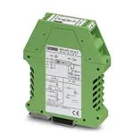
Passive Current Transducers for Sinusoidal
Alternate Currents From 0...1 A/0...5 A
MCR-SLP-1/5-UI-0(-SW)
• Passive current transducer without power supply
• Measuring range 1 A and 5 A AC, reconnectable
• Available with threshold value switches
I
U, I
1. Description
MCR-SLP-1/5-UI-0(-SW) passive current
transducers convert sinusoidal alternate currents from
1 and 5 A into analog standard signals of 0…20 mA or
0…10 V. Modules acquire the necessary power for
signal conversion from the measuring circuit so that a
separate supply is not required for the transducer.
The MCR-SLP-1/5-UI-0-SW current transducer has
an additional limit monitor. The limit value and an alarm
suppression time are set using two potentiometers on
the front of the housing.
One Form A and one Form B contact are available for
the signaling on the output side. The appropriate
switching state is displayed using LEDs.
Both module versions are electrically isolated from
one another on the input and output side.
Safety Note:
MCR-SLP-1/5-UI-0-SW passive current transducers
are not suitable for safety circuits because there is no
response at the relay output if the input current fails.
Headquarters: © Phoenix Contact GmbH & Co. KG • Flachsmarktstraße 8 • 32825 Blomberg • Germany
Phone +49 - 52 35 - 3 00 • Fax +49 - 52 35 - 34 12 00• www.phoenixcontact.com
�Passive Current Transducers for Sinusoidal Alternate Currents 0...1 A / 0...5 A – MCR-SLP-1/5-UI-0(-SW)
2. Technical Data
Setpoint
NC
I O UT
11
13
14
Alarm
O UT
12
5
6
7
8
9
O UT I
0
O UT U
!
GND
"
GND
J
Suppression
5A
114.5
OUT
IN
1
2
3
4
1A
500
99
MCR-SLP-1/5-UI-0(-SW)
with signal conversion:
0…1 A AC, 0…5 A AC/0…20 mA, 0…10 V
available with relay output
8
M3
rigid
[mm2]
flexible
AWG
I
[A]
U
[V]
*
*
Connection data0.2-2.5 0.2-2.5
24-14
* The electrical data is determined by the module.
Description
MCR passive current transducer,
for sinusoidal alternate currents
Without switching output
With switching output
Technical Data
Input
Input current
Frequency range
Curve form
Overcurrent capacity
Surge withstand capability (for 1 second) 1 A input/5 A input
Permissible control range
1 A input/5 A input
Power loss at IA = 20 mA
Connection method
Output
Voltage Output
Maximum output signal
Load
Ripple
Current Output
Maximum output signal
Load
- with simultaneous use of current and voltage output
Ripple
Switching Output
Relay output
Contact material
Maximum switching voltage
Continuous current carrying capacity/maximum inrush current
Cycles at 6 A
Threshold value setting range
Internal hysteresis
Alarm suppression time for threshold of 25%/110%
Housing width 22.5 mm (0.886 in.)
Aa
Type
Order No.
MCR-SLP-1/5-UI-0
MCR-SLP-1/5-UI-0-SW
28 14 35 9
28 14 36 2
Pcs.
Pkt.
1
1
MCR-SLP-1/5-UI-0
MCR-SLP-1/5-UI-0-SW
0…1 A AC and 0…5 A AC
45…50…60 Hz
Sine
2 x IN for 5 min. at 60°C (140˚F)
Ambient temperature
50 A/100 A
1.2 x IN
1.6 VA/2.2 VA
Screw-clamp terminal block
2.5 mm2 (14 AWG)
0…1 A AC and 0…5 A AC
45…50…60 Hz
Sine
2 x IN for 5 min. at 55°C (131˚F)
Ambient temperature
50 A/100 A
1.1 x IN
1.8 VA/2.4 VA
Screw-clamp terminal block
2.5 mm2 (14 AWG)
0…10 V
20 V
> 100 kΩ
< 50 mVpp
0…20 mA
30 mA
< 750 Ω
< 250 Ω
< 0.5%pp of measured value
0…10 V
20 V
> 100 kΩ
< 50 mVpp
0…20 mA
30 mA
< 750 Ω
< 250 Ω
< 0.5%pp of measured value
–
1 Form A contact, 1 Form B
contact
AgSnO
250 V AC/60 V DC
2 A/6 A
> 100 000
25…110% of IN using
potentiometer
Approximately 3% of final value
0.25…10 s/0.15…6.5 s
PHOENIX CONTACT page 2 of 5
�Passive Current Transducer for Sinusoidal Alternate Currents 0...1 A / 0...5 A – MCR-SLP-1/5-UI-0(-SW)
General Data
Transmission error
Temperature coefficient
Step-response (10-90%)
rated isolation voltage
Test voltage:
Input/output/power supply
Protective circuit
Ambient temperature range
Mounting position/mounting
< 0.5% of final value
< 0.015%/K
50°C (122˚F): perpendicular 1)
1
< 2% of final value
< 0.015%/K
45°C (113˚F): perpendicular 1)
) Mounting on a horizontal DIN rail.
c
Conforms to the EMC Directive 89/336/EEC and the
Low Voltage Directive 73/23/EEC
EMC (electromagnetic compatibility)
Noise immunity in accordance with EN 50082-2
• Electrostatic discharge (ESD)
EN 61000-4-2
8 kV air discharge2)
6 kV contact discharge2)
• Electromagnetic HF field
Amplitude modulation
Pulse modulation
EN 61000-4-3
10 V/m1)
10 V/m1)
• Fast transients (burst)
EN 61000-4-4
Input/output 2 kV/5 kHz2)
• Surge current load (surge)
EN 61000-4-5
Input/output: 2 kV/42 Ω2)
• Conducted interference
EN 61000-4-6
Input/output
10 V1)
Class B
EN 55022
Noise emission in accordance with EN 50081-2
These results were achieved using shielded cables.
EN 61000 corresponds to IEC 1000/
EN 55022 corresponds to CISPR22
1)
Criterion A: Normal operating characteristics within the specified
limits.
Criterion B: Temporary adverse effects on the operating
characteristics, which the device corrects itself.
2)
Industrial and domestic applications
1
2
1
1
1
0
T
U
U
N
G
2
D
2
2
D
N
G
T
OU
IN
1A
IN
5A
C
N
7
O
D
1
4
2
3
I-0
-U 54 9
-1/5 3
LP 14
R-S: 28
MC.-Nr.
Art
6
T
U
O
N
G
C
N
5
3
9
Ι
2
D
N
G
I-0
-U
-1/5
LP
R-S
MC
IN
5A
2
T
U
O
T
U
U
O
T
U
O
T
OU
IN
1A
1
1
Ι
1
0
T
U
O
I-0
-U
-1/5
LP
R-S
MC
1 SETPOINT/TIME potentiometer
2 LED switching state indicator
2
1
1
1
2
MCR-SLP-1/5-UI-0(-SW) – Passive Current
Transducer for Sinusoidal Alternate Currents From
0...1 A/0...5 A
9
Class B:
5
6
8
T
OU
10
7
8
IN
1
3 Housing cover, can be removed for jumper setting
9
t
Ι ou
11
J
0
50
Ω
12
I-0
-U 5 9
-1/5 3
LP 14
R-S: 28
MC.-Nr.
tΙ
Ou
Art
tU
Ou
D
GN
D
GN
3
NC
4
10
IN
2
1
11
0
50
Ω
1
J
9
t
Ι ou
J
2
1A
5A
T
OU
1A
5A
2
NC
4
12
tΙ
Ou
tU
Ou
D
GN
D
GN
3
J
2
1
t
U ou
4 Metal lock for fastening on
the DIN rail
12
9
10
11
12
J
t
Ι ou
12
R
Ι ou
9
S
t
U ou
N
NE
/
11
AL
OV
A
0m
...2
2
RB
t=0 0V
Ι ou =0...1
t
0Ω U ou
< 250kΩ
12
PR
AP
11
B
RO
12
12
S
t
U ou
Ι ou =0...1
t
U ou
N
AL
OV
A
0m
...2
t=0 0V
2
0Ω
< 250kΩ
R B1> 50
R B2
/
PR
AP
NE
TIO
BA
O
PR
AP
MCR-SLP-...-SW
PHOENIX CONTACT page 3 of 5
MCR-SLP-...
4
Ω
0k
> 50 0V
R B =0...1
t
U ou
11
t
Ι ou R B1
RB
IO
AT
10
RB
10
RB
9
2.)
P
AP
2
1
0Ω A
< 75 0m
R B t=0...2
Ι ou
1.)
t
Ι ou R B1
R B1> 50
R B2
t
U ou
Ω
0k
> 50 0V
R B =0...1
t
U ou
11
0Ω A
< 75 0m
B =0...2
t
11
RB
10
RB
1.)
2.)
2
1
J
t
Ι ou
9
3
�Passive Current Transducers for Sinusoidal Alternate Currents 0...1 A / 0...5 A – MCR-SLP-1/5-UI-0(-SW)
3. Configuration of the Output
2
3.1. Opening the Device
The locked housing cover is released on both sides
using a screwdriver1. The housing cover and
electronics can only be pulled out about 3 cm
(1.181 in.) 2.
5
6
7
3
4
8
IN
1
2
1
1A
5A
3
NC
4
2
5
12 6
11
7
13 8
14
J
t
Ι ou
1.)
9
11
12
3.2. Jumper Position 1
(Current Output/Current and
Voltage Output Parallel)
The 0-20 mA output signal is received by connecting
terminal points 9 and !. The maximum load is 750 Ω.
J
1.)
9
1 2
Ι out
RB
11
12
R B < 750Ω
If the 0-20 mA current and the 0-10 V voltage
signal are required simultaneously, this can be
implemented by connecting the terminal points
according to the diagram opposite:
Terminal points 9 and 0, are used to close the
current path.
The voltage signal 0-10 V can be tapped (by leading
back the current via the internal 500 Ω resistor) on the
output side of connections 0 and !.
Since the total of all loads in the current path must
not exceed 750 Ω, a maximum external load of 250 Ω
is to be maintained for this connection method.
In the voltage path, loads of 500 kΩ must not be
exceeded. Additional measuring errors, which must be
taken into account, can be found in the Technical Data.
PHOENIX CONTACT page 4 of 5
J
2.)
9
Ι out=0...20mA
1 2
Ι out
R B1
10
11
R B2
U out
12
R B1< 250Ω Ι out=0...20mA
R B2> 500kΩ U out=0...10V
1
R
�Passive Current Transducers for Sinusoidal Alternate Currents 0...1 A / 0...5 A – MCR-SLP-1/5-UI-0(-SW)
3.3. Jumper Position 2
(Voltage Output/Limit Value Indicator)
The 0-10 V signal is received by connecting terminal
points 0 and !.
In the voltage path, loads of 500 kΩ must not be
exceeded. Additional measuring errors, which must be
taken into account, can be found in the Technical Data.
J
In jumper position 2, there is an option with the
MCR-SLP-1/5-UI-0-SW module, to use the device
without an analog output, i.e., purely as a limit value
indicator.
1 2
10
U out
RB
11
12
R B > 500kΩ
U out=0...10V
1
1
1
1
T D
U GN
OU
T
U
O
9
Ι
E
IM
T
T
IN
O
P
T
D
N
E
G
S
-
LP
-S
R
MC
0
T
U
O
W
-S
I-0
-U
1/5
L
1A
H
5. Default Setting
PHOENIX CONTACT
October 10, 2000
For the MCR-SLP-1/5-UI-0 the jumper is in position
1 upon delivery (see Page 4).
For the MCR-SLP-1/5-UI-0-SW, the jumper is in
position 2 upon delivery 2 (see above).
W
-S
I-0
-U 6 2
5
/
1 3
P- 4
SL 1
http://www.phoenixcontact.com
4
TNR: 5087439-02
C
4
IN N UT 1
O
IS 13
A
L
E 1
R 1
5A
The desired current limit value is set for the MCRSLP-1/5-UI-0-SW module using the SETPOINT
potentiometer.
The TIME potentiometer enables an additional alarm
suppression time of 0.2 – 6 seconds.
This means that the relay is only activated if the
current limit value is still being exceeded after the
alarm suppression time has elapsed.
This function is useful, for example, if on starting AC
motors, no alarm is to be triggered due to the high
startup current.
2
4. Settings (SETPOINT/TIME)
for MCR-SLP-1/5-UI-0-SW
PHOENIX CONTACT page 5 of 5
�
很抱歉,暂时无法提供与“2814359”相匹配的价格&库存,您可以联系我们找货
免费人工找货- 国内价格
- 1+1947.29400
- 200+753.58080
- 500+727.09920
- 1000+714.00960