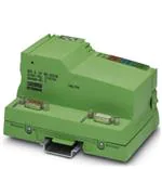
IBS IL 24 BK-DSUB ...
INTERBUS Inline Bus Coupler;
Remote Bus Connections Via D-SUB Connectors
UL
BA D
R
RC LD
UB
DS
TE
MO
IN
RE
TE
MO
RE
Data Sheet
6362_en_03
© PHOENIX CONTACT - 11/2007
co
Description
When using a terminal with remote bus branch
(IBS IL 24 RB-T...), please refer to page 14.
nt
s.
The bus coupler connects an Inline station to the
INTERBUS remote bus. It provides the supply voltages UL
and UANA for the connected devices.
om
po
The end plate is supplied with the bus coupler. Place this
plate at the end of the Inline station. The termination plate
has no electrical function. It protects the station from ESD
pulses and the user from dangerous voltage.
A power terminal must be connected after the
bus coupler to supply the main and segment
voltage to the subsequent terminals.
in
ec
–
Please note that the power terminal is not
supplied with the bus coupler. To order this
terminal, please refer to the "Ordering Data" on
page 2 or to the latest "AUTOMATION" catalog.
on
l
–
–
Remote bus connections using copper cables via
D-SUB connectors
Electrical isolation to the remote bus segments
Automatic configuration of the outgoing interface as
remote bus or local bus interface
Support of up to 15 connected terminals with remote
bus branch
ne
Features
–
m
AUTOMATIONWORX
T
OU
This data sheet is only valid in association with the IB IL SYS PRO UM E user manual.
Make sure you always use the latest documentation.
It can be downloaded at www.download.phoenixcontact.com.
A conversion table is available on the Internet at
www.download.phoenixcontact.com/general/7000_en_00.pdf.
This data sheet is valid for the products listed on the following page:
�IBS IL 24 BK-DSUB ...
Ordering Data
Products
Description
Order No.
Pcs./Pck.
IBS IL 24 BK-DSUB
2742104
1
INTERBUS bus coupler with D-SUB connection,
with accessories (connector and labeling field);
500 kbps transmission speed
IBS IL 24 BK-DSUB-PAC
2861593
1
INTERBUS bus coupler with D-SUB connection,
without accessories;
2 Mbps transmission speed
IBS IL 24 BK-DSUB-2MBD
2855949
1
INTERBUS bus coupler with D-SUB connection,
with accessories (connector and labeling field);
2 Mbps transmission speed
IBS IL 24 BK-DSUB-2MBD-PAC
2826123
1
Accessories
Description
co
m
Type
INTERBUS bus coupler with D-SUB connection,
without accessories;
500 kbps transmission speed
Order No.
Pcs./Pck.
s.
Type
nt
Two D-SUB connectors are required for connecting INTERBUS. The connectors are not supplied as standard.
IBS DSUB 9/L
2758473
1
Bus connector, crimp connection, male/female connector
IBS DSUB 9/C
2758486
1
ne
Bus connector, solder connection, male/female connector
po
A connector is required to provide the bus coupler supply for the IBS IL 24 BK-DSUB and IBS IL 24 BK-DSUB-2MBD terminals.
Inline connector, with color print
IB IL SCN-8-CP
2727608
10
Power terminal with fuse (UM, US)
Power terminal without fuse
Power terminal with fuse (UM, US)
om
Power Terminal, Complete With Accessories (Connector and Labeling Field),
500 kbps and 2 Mbps Transmission Speed
IB IL 24 PWR IN/2-F-PAC
2862136
1
IB IL 24 PWR IN-PAC
2861331
1
IB IL 24 PWR IN/F-PAC
2861438
1
in
ec
Power Terminal, Complete With Accessories (Connector and Labeling Field), for 500 kbps
Power terminal with fuse (UM, US) and diagnostics
IB IL 24 PWR IN/2-F-D-PAC
2862152
1
Power terminal with fuse (UM, US) and diagnostics
IB IL 24 PWR IN/F-D-PAC
2861894
1
Power terminal with fuse (UM, US) and diagnostics
IB IL 24 PWR IN/2F-DF-PAC
2863779
1
Power Terminal, Complete With Accessories (Connector and Labeling Field), for 2 Mbps
IB IL 24 PWR IN/2F-DF-2MBD-PAC
2863834
1
Power terminal with fuse (UM, US) and diagnostics
IB IL 24 PWR IN/2F-D-2MBD-PAC
2863821
1
Documentation
Description
Type
Order No.
Pcs./Pck.
IB IL SYS PRO UM E
2743048
1
on
l
Power terminal with fuse (UM, US) and diagnostics
"Configuring and Installing the INTERBUS Inline Product Range" user
manual
6362_en_03
PHOENIX CONTACT
2
�IBS IL 24 BK-DSUB ...
Technical Data
General Data
Housing dimensions (width x height x depth)
90 mm x 120 mm x 71.5 mm
Weight
210 g (without connector); 225 g (with connector)
Ambient temperature (operation)
-25°C to +55°C
Ambient temperature (storage/transport)
-25°C to +85°C
Permissible humidity (operation/storage/transport)
10% to 95%, according to DIN EN 61131-2
Permissible air pressure (operation/storage/transport)
70 kPa to 106 kPa (up to 3000 m above sea level)
Degree of protection
IP20 according to IEC 60529
Protection class
Class 3 according to VDE 0106, IEC 60536
Connection data
Spring-cage terminals
Conductor cross-section
0.2 mm2 to 1.5 mm2 (solid or stranded), 24 - 16 AWG
co
Interfaces (INTERBUS)
Remote Bus
m
Connection type
Copper cable (RS-422), connected via D-SUB connector; electrically isolated
supply; shielding connected with a capacitor to functional earth ground
Outgoing remote bus
Copper cable (RS-422), connected via D-SUB connector; electrically isolated
supply; shielding directly connected to functional earth ground
Recommended cable lengths
See INTERBUS system data
Observe current consumption of the terminals
ne
nt
s.
Incoming remote bus
po
Observe the logic current consumption of each device when configuring an Inline station. It is specified in every terminal-specific data sheet.
The current consumption can differ depending on the individual terminal. The permissible number of devices that can be connected therefore
depends on the specific station structure.
Functional
If the next device is snapped on, the bus coupler automatically configures the
interface.
If the next device is a terminal with remote bus branch, the interface is
configured as a remote bus interface.
For every other device (e.g., I/O terminal) the interface is configured as a local
bus interface with diagnostics.
on
l
in
ec
om
Interface configuration (internal)
6362_en_03
PHOENIX CONTACT
3
�IBS IL 24 BK-DSUB ...
24 V Bus Coupler Supply
Connections
See Figure 4 on page 11
Connection method
Spring-cage terminals
Recommended cable lengths
30 m, maximum; routing cables through outdoor areas is not admissible
Continuation
Via potential routing
Special demands on the voltage supply
The bus coupler supply UBK is electrically isolated from UM/US if it is supplied
separately. This is only ensured if two separate power supply units are used.
Nominal value
24 V DC
Tolerance
-15%/+20% (according to EN 61131-2)
Ripple
±5%
19.2 V to 30 V
Minimum current consumption at nominal voltage
0.10 A DC
(At no-load operation, i.e., incoming remote bus connected, no local bus
devices connected, bus inactive)
Maximum current consumption at nominal voltage
1.25 A DC
consisting of:
0.75 A DC for communications power
0.5 A DC for analog voltage supply
Safety equipment
For the bus coupler supply only
Yes
Polarity reversal
Yes
nt
Surge voltage
s.
co
m
Permissible range
Provide an external fuse for the 24 V area
7.5 V DC
om
Nominal value
po
24 V Module Supply
Communications Power (Potential Jumpers)
ne
This 24 V area must be externally protected. The power supply unit must be able to supply 4 times (400%) the nominal current of the external
fuse, to ensure that the fuse blows safely in the event of an error.
Tolerance
Ripple
Maximum output current
in
ec
Safety equipment
±5%
±1.5%
2 A DC (observe derating)
Electronic short-circuit protection
Communications Power (Interfaces)
Nominal value
Tolerance
Ripple
on
l
Maximum output current
Safety equipment
2 x 5 V DC
±5%
±1.5%
2 x 0.15 A DC
None
Communications Power (Internal)
Nominal value
Tolerance
1 x 5 V DC
±5%
Ripple
±1.5%
Maximum output current
1 x 0.15 A DC
Safety equipment
None
Analog Supply (Potential Jumpers)
Nominal value
24 V DC
Tolerance
-15%/+20%
Ripple
±5%
Maximum output current
0.5 A DC (observe derating)
Safety equipment
Electronic short-circuit protection
6362_en_03
PHOENIX CONTACT
4
�IBS IL 24 BK-DSUB ...
Derating of the Communications Power and the Analog Terminal Supply
100
90
80
70
50
40
m
P [%]
60
30
co
20
10
0
5
10
15
20
25
30
35
40
45
50
55
6291A006
nt
TA [°C]
s.
0
Current carrying capacity of the power supply unit for communications power (UL) and analog supply (UANA) in %
TA [°C]
Ambient temperature in °C
ne
P [%]
po
Power Dissipation
Formula to Calculate the Power Dissipation of the Electronics
PEL = PBUS + PPERI
om
a
b
PEL = 1.6 W + (1.375 Wx S ILn) + (0.7 Wx S ILm)
A m=1
A n=1
Total power dissipation in the terminal
Power dissipation for bus operation without I/O load (permanent)
Power dissipation with I/O connected
ILn
n
a
Current consumption of device n from the communications power
Index of the number of connected devices (n = 1 to a)
Number of connected devices (supplied with communications power)
n=1
ILm
m
b
Total current consumption of the devices from the 7.5 V communications power (2 A, maximum)
on
l
a
S ILn
in
ec
Where:
PEL
PBUS
PPERI
Current consumption of the device m from the analog supply
Index of the number of connected analog devices (m = 1 to b)
Number of connected analog devices (supplied with analog voltage)
Total current consumption of the devices from the 24 V analog supply (0.5 A, maximum)
b
S ILn
m=1
6362_en_03
PHOENIX CONTACT
5
�IBS IL 24 BK-DSUB ...
Power Dissipation/Derating
Using the maximum currents 2 A (logic current) and 0.5 A (current for analog terminals) in the formula to calculate the power dissipation when the I/O is
connected results in the following:
PPERI = 2.75 W + 0.35 W = 3.10 W
3.1 W correspond to 100% current carrying capacity of the power supply unit in the derating curves on page 5.
Ensure that the indicated nominal current carrying capacity in the derating curves is not exceeded when the ambient temperature is above 45°C.
Corresponding to the formula, the total current carrying capacity of the connected I/O (PPERI) is relevant. If, for example, no current is drawn from the analog
supply, the percentage of current coming from the communications power may be increased.
Example:
Ambient temperature: 55°C
Nominal current carrying capacity of communications power and analog supply: 75% according to the diagram
m
ILLogic = 1.5 A, ILAnalog = 0,375 A
PPERI = 2.0625 W + 0.2625 W
co
PPERI = 2.325 W (corresponds to 75% of 3.10 W)
Possible logic current if the analog supply is not loaded:
s.
PPERI = 1.375 W/A x ILLogic + 0 W
PPERI / 1.375 W/A = ILLogic
nt
ILLogic = 2.325 W / 1.375 W/A
ILLogic = 1.691 A
ne
Error Messages to the Higher-Level Control or Computer System
I/O error
No
po
Safety Equipment
Surge voltage
(bus coupler supply)
Input protective diodes (can be destroyed by permanent overload)
Pulse loads up to 1500 W are short circuited by the input protective diode.
om
Polarity reversal
(bus coupler supply)
Serial diode in the lead path of the power supply unit; in the event of an error
only a low current flows. In the event of an error, no fuse trips within the
external power supply unit.
in
ec
If you want to protect the bus coupler supply UBk, use a 2 A medium blow fuse.
Electrical Isolation/Isolation of the Voltage Areas
on
l
Please note that the bus coupler supply UBK must be supplied at the bus coupler and the supplies UM/US must be supplied at a separate
power terminal.
Common Potentials
When providing the 24 V bus coupler supply
separately from the 24 V main supply/24 V
segment supply
Main and segment supply galvanically have the same potential. From the bus coupler onwards, common
ground is led through the potential jumper to the devices as the reference ground GND.
When providing the 24 V bus coupler supply
by jumpering the 24 V main supply/24 V
segment supply
Bus coupler supply, main supply, segment supply, 24 V analog supply, and 7.5 V communications power
galvanically have the same potential. From the bus coupler onwards, common ground is led through the
potential jumper to the devices as reference ground LGND for the communications power and analog supply
and separately as reference ground GND for the supply and segment level.
6362_en_03
Bus coupler supply, 24 V analog supply, and 7.5 V communications power galvanically have the same
potential. From the bus coupler onwards, common ground is led through the potential jumper to the devices
as the reference ground LGND.
PHOENIX CONTACT
6
�IBS IL 24 BK-DSUB ...
Electrical Isolation/Isolation of the Voltage Areas (Continued)
Separate Potentials
When providing the 24 V bus coupler supply
separately from the 24 V main supply/
24 V segment supply:
The bus coupler supply is physically and therefore electrically isolated from the main and segment supply.
When providing the 24 V bus coupler supply
by jumpering the 24 V main/
24 V segment supply:
The bus coupler has two interface supplies for the incoming and outgoing remote bus that are electrically
isolated from one another and from the primary/secondary supply.
The interface supplies for the incoming and outgoing remote bus are electrically isolated from one another and
from the supplies.
The main supply is electrically isolated from the interface supplies.
Electrical Isolation/Isolation of the Voltage Areas
Test Distance
Test Voltage
5 V supply incoming remote bus /
5 V supply outgoing remote bus
m
500 V AC, 50 Hz, 1 min
5 V supply incoming remote bus /
7.5 V communications power, 24 V analog supply, 24 V bus terminal supply
500 V AC, 50 Hz, 1 min
500 V AC, 50 Hz, 1 min
co
5 V supply incoming remote bus /
functional earth ground
5 V supply outgoing remote bus /
7.5 V communications power, 24 V analog supply, 24 V bus terminal supply
500 V AC, 50 Hz, 1 min
500 V AC, 50 Hz, 1 min
on
l
in
ec
om
po
For the latest approvals, please visit www.download.phoenixcontact.com.
nt
Approvals
500 V AC, 50 Hz, 1 min
ne
7.5 V communications power, 24 V analog supply, 24 V bus coupler supply /
functional earth ground
s.
5 V supply outgoing remote bus /
functional earth ground
6362_en_03
PHOENIX CONTACT
7
�IBS IL 24 BK-DSUB ...
Local Diagnostic and Status Indicators
Remote Bus Connections
REMOTE IN
TE
MO
RE
TE
MO
IN
UL
RE
TE
MO
RE
BA
RD
RE
TE
MO
OU
REMOTE OUT
LD
m
9
ne
po
om
6
Figure 2
X
Y
Y
/DO
DO
/DI
DI
reserved
GND
not conn.
reserved
+5 V
6
1
7
2
8
3
9
4
5
6
1
9
5
6362B004
Assignment of the remote bus interfaces
Remote OUT (outgoing remote bus)
Remote IN (incoming remote bus)
on
l
in
ec
BA
RC
RD
LD
5
/DO
DO
/DI
DI
reserved
GND
not conn.
reserved
+5 V
nt
1
Color Meaning
Green 24 V bus coupler supply/
7.5 V communications power/
interface supply
Green Bus active
Green Remote bus cable check
Yellow Outgoing remote bus switched off
Yellow Local bus disabled
6
1
7
2
8
3
9
4
5
s.
X
Diagnostic indicators of the terminal
co
6362A003
Des.
UL
T
OU
RC
T
DSUB
Figure 1
IN
6362_en_03
PHOENIX CONTACT
8
�IBS IL 24 BK-DSUB ...
Connecting Bus Cables
•
Assemble the D-SUB connectors according to the
specifications in the following section.
•
Plug the connectors into the appropriate connections.
•
Secure the connectors using knurled-head screws.
Signal
Remark/
Wire Color in the INTERBUS Standard
Cable
/DO
Green
Yellow
/DI
Pink
DI
Gray
GND
Brown
Shield
(incoming
remote bus)
Shield potential is connected with a
capacitor to functional earth ground (FE)
of the potential jumper.
Shield
(outgoing
remote bus)
Shield potential is directly connected to
functional earth ground (FE) of the
potential jumper.
on
l
in
ec
om
po
ne
nt
s.
co
m
DO
6362_en_03
PHOENIX CONTACT
9
�IBS IL 24 BK-DSUB ...
Assembling D-SUB Connectors
Type:
9-pos. D-SUB connector, male and female,
mechanical protection against polarity reversal
IBS DSUB 9/L (solder connection), Order No. 2758473
IBS DSUB 9/C (crimp connection), Order No. 2758486
Order designation:
2 0 m m
(0 .7 9 ")
A
8 m m
C
(0 .3 2 ")
B
C 2
(0 .1 2 ")
s.
co
3 m m
m
C 1
nt
E
Figure 3
6 3 6 2 A 0 0 9
Assembling D-SUB connectors
Strip 20 mm off the cable sheath (A).
Shorten the shielding to 8 mm (A).
Fold the shielding uniformly back over the sheath (A).
Strip 3 mm off the wires. Cut off the white wire (B).
Solder the wires to the contacts or crimp them using
crimping pliers (C).
The contacts of a connector in crimp design must be
inserted into the contact housing.
•
To ensure optimum shielding, as much of the
shielding as possible must have contact with
the shield connection clamp and the mounting
base housing. The shield connection clamp
also provides strain relief.
•
6362_en_03
on
l
•
•
•
•
•
in
ec
om
po
ne
D
Place the cables with their contact housing in the slot
of the mounting base housing and connect the
shielding of the cable with the shield connection clamp
by screwing them together (D).
Screw the shield connection clamp on tightly using the
two countersunk screws.
The wires must not be squeezed between the
housing parts.
Insert the interlocking screws into the drill holes of the
contact housing and place them into the guideways of
the mounting base housing.
Snap the upper part of the housing on the mounting
base housing and fasten these parts together using the
two socket-head cap screws (E).
PHOENIX CONTACT
10
�IBS IL 24 BK-DSUB ...
Connection of the Bus Coupler Supply
1
RE
IN
TE
MO
TE
MO
T
OU
1.1
1
1
2.1
1.2
2
2
2.2
1.3
3
3
2.3
1.4
4
4
2.4
co
m
RE
2
6362A005
Terminal point assignment
s.
Figure 4
1.4, 2.4
FE
Reserved
24 V DC
BK-GND
Remark/
Wire Color in the INTERBUS Standard Cable
ne
Assignment
UBK
GND
in
ec
om
Functional
earth ground
24 V bus coupler supply; supply of the bus coupler power supply unit
GND of the bus coupler supply
This potential is reference ground for the bus coupler electronics.
Connection of the bus coupler and therefore of the Inline station to functional
earth ground
The contacts are directly connected to the potential jumper and the FE
spring on the bottom of the housing.
po
Terminal
Point
1.1, 2.1
1.2, 2.2
1.3, 2.3
nt
Terminal Point Assignment
Functional earth ground is only used to discharge interference.
on
l
Ground the bus coupler
Connect the bus coupler to functional earth ground via one of the FE connections of the connector. For this,
connect the corresponding contact with a grounding terminal (see also Figure 7 on page 14).
In addition, the bus coupler is automatically connected to functional earth ground by snapping it onto a
grounded DIN rail.
24 V Bus Coupler Supply
The bus coupler supply is protected against polarity reversal and surge voltage. These protective elements are only used
to protect the power supply unit.
Ensure short-circuit protection
The bus coupler supply does not have short-circuit protection.
The user must provide short-circuit protection. The rating of the preconnected fuse must be such that the
maximum permissible load current is not exceeded.
6362_en_03
PHOENIX CONTACT
11
�IBS IL 24 BK-DSUB ...
Internal Basic Circuit Diagram
Local bus
OPC
UL
UL
UANA
RS-422
interface
7.5 V
5V
5V
24 V
BA
24 V
RD
RC
24 V
LD
m
5V
24 V
s.
po
D-SUB connector
Interface component
Optocoupler
om
R S -4 2 2
in te r fa c e
Power supply unit with electrical isolation
in
ec
6362C006
nt
Internal wiring of the terminal points
ne
Figure 5
co
RS-422
interface
OPC
Converter
INTERBUS protocol chip (bus logic including
voltage conditioning)
Diode
LED with function identification
on
l
Other symbols used are explained in the
IB IL SYS PRO UM E user manual.
6362_en_03
PHOENIX CONTACT
12
�IBS IL 24 BK-DSUB ...
Electrical Isolation
1
Local bus
OPC
RS-422
interface
UL
5
5V
5V
524 V
7.5 V
UL+
UANA
UL-
BA
24 V
RD
RC
24 V
3
LD
2
m
5V
24 V
co
RS-422
interface
Figure 6
6362C007
nt
s.
4
Electrical isolation of individual function areas (separate power supply units)
om
po
Area of incoming remote bus
Area of outgoing remote bus
Area of functional earth ground (FE, capacitive)
Area of functional earth ground (FE)
Area of bus coupler supply UBK from which the communications power UL and the analog terminal
supply UANA are generated
on
l
in
ec
1
2
3
4
5
ne
Potential areas when using separate power supply units to supply UBK and UM/US:
6362_en_03
PHOENIX CONTACT
13
�IBS IL 24 BK-DSUB ...
Connection Example
Information for Using Terminals With
Remote Bus Branch
Up to 15 terminals with remote bus branch can be installed
after the bus coupler.
UL
As of hardware revision 02, the IBS IL 24 RB-T terminal
with remote bus branch is no longer supplied from the
segment circuit but from the analog circuit. This provides
various options for supplying the main and segment voltage
to the subsequent terminals.
BA
RD
RC
LD
DSUB
REMOTE IN
2
1
1
2
2
+
REMOTE OUT
3
4
4
-
The power terminal can be installed after the terminal with
remote bus branch. In this case, there are no restrictions.
co
3
The power terminal can be installed before the terminal
with remote bus branch. In this case, only a power terminal,
which is not a bus device, may be installed.
24 V DC
(UBK)
m
1
Typical connection of the cables to the bus
coupler
nt
00hex
Input address area
0 bytes
Output address area
0 bytes
Parameter channel (PCP)
0 bytes
Register length (bus)
0 bytes
on
l
in
ec
© PHOENIX CONTACT 11/2007
04hex (04dec)
Length code
om
po
Connect the cables according to the
information in the "Configuring and Installing
the INTERBUS Inline Product Range" user
manual.
ID code
ne
Figure 7
Programming Data
6362B008
s.
FE
6362_en_03
PHOENIX CONTACT GmbH & Co. KG • 32823 Blomberg • Germany
Phone: +49-(0) 5235-3-00 • Fax: +49-(0) 5235-3-4 12 00
www.phoenixcontact.com
14
�