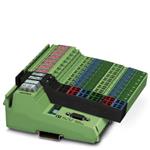
ILB PB 24 DO32
Inline Block IO Module
for PROFIBUS With 32 Digital Outputs
AUTOMATIONWORX
Data Sheet
6889_en_04
© PHOENIX CONTACT - 03/2007
6 8 8 9 A 0 0 1
Description
The ILB PB 24 DO32 module is designed for use within a
PROFIBUS network. It is used to output digital signals.
PROFIBUS-DP Features
–
–
–
–
–
–
Bus connection via D-SUB connectors
Rotary encoding switches for address setting
Supported PROFIBUS addresses 1 to 99
Transmission speed 9.6 kbaud to 12 Mbaud (autobaud)
Diagnostic and status indicators
Device description via GSD file
Output Features
–
–
–
–
–
–
Connections for 32 digital actuators
Connection of actuators in 2 and 3-wire technology
Nominal current per output: 0.5 A
Total current of all outputs: 16 A (4 x 4 A)
Short-circuit and overload protected outputs
Diagnostic and status indicators
Please refer to the "Mounting and Removing Inline Block IO Modules" application note (see "Ordering Data"
on page 2).
Make sure you always use the latest documentation.
It can be downloaded at www.download.phoenixcontact.com.
A conversion table is available on the Internet at
www.download.phoenixcontact.com/general/7000_en_00.pdf.
�ILB PB 24 DO32
Ordering Data
Product
Description
Type
Order No.
Pcs./Pkt.
Inline Block IO module for PROFIBUS with 32 digital outputs
ILB PB 24 DO32
2862408
1
Accessories: Connector
Description
Type
Order No.
Pcs./Pkt.
9-pos. D-SUB connector for connecting PROFIBUS
SUBCON-PLUS-PROFIB
2744348
1
Accessories: Connectors as Replacement Item
Description
Type
Order No.
Pcs./Pkt.
Connector for the supply (color print)
ILB SCN-12-PWR IN-CP
2863164
10
Connector, with color print, for digital 4-channel or 16-channel Inline output
terminals
IB IL SCN-12-OCP
2727624
10
Accessories: Other
Description
Type
Order No.
Pcs./Pkt.
CLIPFIX 35-5
3022276
50
Documentation
Description
Type
Order No.
Pcs./Pkt.
"Mounting and Removing Inline Block IO Modules" application note
AH ILB INSTALLATION
9014931
1
"Addressing of 32-Channel ILB Modules" application note
AH ILB 24 DI/DO 32 ADDRESS
9014963
1
Recommended end clamp; placed both to the right and left of the module to
secure it on the DIN rail
6889_en_04
PHOENIX CONTACT
2
�ILB PB 24 DO32
Technical Data
General Data
Housing dimensions with connectors (width x height x depth)
156 mm x 55 mm x 141 mm
Weight
510 g (with connectors)
Operating mode
Process data mode with 4 bytes
Transmission speed
9.6 kbaud to 12 Mbaud (autobaud)
Connection method for actuators
2 and 3-wire technology
Housing Dimensions
55
141
120
156
6889B003
Figure 1
Housing dimensions of the module (dimensions in mm)
Ambient Conditions
Regulations
Developed according to VDE 0160/EN 50178/IEC 62103, UL 508
Ambient temperature (operation)
-25°C to +60°C
Ambient temperature (storage/transport)
-25°C to +85°C
Humidity (operation/storage/transport)
10% to 95% according to EN 61131-2
Air pressure (operation)
80 kPa to 108 kPa (up to 2000 m above sea level)
Air pressure (storage/transport)
66 kPa to 108 kPa (up to 3500 m above sea level)
Degree of protection according to IEC 60529
IP20
Class of protection
Class 3 according to VDE 0106/IEC 60536
Air and creepage distances
According to DIN VDE 0110/IEC 60664, IEC 60664A,
DIN VDE 0160/EN 50178/IEC 62103
Housing material
Plastic, PVC-free, PBT, self-extinguishing (V0)
Pollution degree according to
EN 60664-1/IEC 60664-1, EN 61131-2/IEC 61131-2
2; condensation not permitted during operation
Surge voltage class
II
6889_en_04
PHOENIX CONTACT
3
�ILB PB 24 DO32
Electrical Isolation/Isolation of the Voltage Areas
Test Distance
Test Voltage
PROFIBUS / I/O
500 V AC, 50 Hz, 1 min
PROFIBUS / functional earth ground
500 V AC, 50 Hz, 1 min
I/O / functional earth ground
500 V AC, 50 Hz, 1 min
Mechanical Requirements
Vibration test, sinusoidal vibrations according to
EN 60068-2-6/IEC 60068-2-6
5g load, 2.5 hours in each space direction
Shock test according to EN 60068-2-27/IEC 60068-2-27
25g load for 11 ms, half sinusoidal wave,
3 shocks in each space direction and orientation
Broadband noise according to EN 60068-2-64/IEC 60068-2-64
0.78g load, 2.5 hours in each space direction
Conformance With EMC Directive 89/336/EEC
Noise Immunity Test According to EN 61000-6-2
Electrostatic discharge (ESD)
EN 61000-4-2
IEC 61000-4-2
Criterion B
Electromagnetic fields
EN 61000-4-3
IEC 61000-4-3
Criterion A
Fast transients (burst)
EN 61000-4-4/
IEC 61000-4-4
Criterion B
6 kV contact discharge
8 kV air discharge
Field strength: 10 V/m
Remote bus: 2 kV
Power supply: 2 kV
I/O cables: 2 kV
Criterion A
All interfaces: 1 kV
Surge voltage
EN 61000-4-5
IEC 61000-4-5
Criterion B
DC supply lines: ±0.5 kV/±1.0 kV (symmetrical/asymmetrical)
Signal cables: ±0.5 kV/±0.5 kV (symmetrical/asymmetrical)
Conducted interference
EN 61000-4-6
IEC 61000-4-6
Criterion A
Test voltage 10 V
Noise Emission Test According to EN 61000-6-4
Noise emission of housing
EN 55011
Class A
Interface
PROFIBUS interface
Copper cable (RS-485); connected via D-SUB connector;
shielding directly connected with functional earth ground
24 V Module Supply (Communications Power and Actuator Supply; UL and UA)
Nominal value
24 V DC
Tolerance
-15%/+20% according to EN 61131-2
Ripple
±5% according to EN 61131-2
Permissible range
19.2 V DC to 30.0 V DC
Current consumption at UL
70 mA
Current consumption at UA1 and UA2
8 A each
Safety equipment for communications power
Surge protection and protection against polarity reversal
Safety equipment for the actuator supply
Surge protection
Connection
Via power connectors
6889_en_04
PHOENIX CONTACT
4
�ILB PB 24 DO32
Digital Outputs
Number
32
Connection method for actuators
2 and 3-wire technology
Nominal output voltage UOUT
24 V DC
Differential voltage at Inom
≤1V
Nominal current Inom per channel
0.5 A
Total current
4x4A
Protection
Short-circuit and overload protection
Nominal load
Ohmic
48 Ω/12 W
Lamp
12 W
Inductive
12 VA (1.2 H, 50 Ω)
0.5 Hz (1.2 H, 50 Ω), maximum
Switching frequency with nominal inductive load
Overload response
Auto restart
Response with inductive overload
Output may be damaged
Reverse voltage protection against short pulses
Protected against reverse voltages
Resistance to permanently applied reverse voltages
Protected against reverse voltages, permissible current 2 A, maximum
Validity of output data after connecting the 24 V supply voltage (power up)
1 ms, typical
Response upon power down
The output follows the supply voltage without delay.
Limitation of the voltage induced on circuit interruption
-41.0 V
One-time unsolicited energy
1 J, maximum
Protective circuit type
Integrated free running circuit in the output chip
Overcurrent shutdown
0.7 A, minimum
Maximum output current when switched off
10 µA
When not loaded, a voltage can be measured even at an output that is not set.
Typical Power Dissipation With 24 V Supply Voltage
Formula to Calculate the Power Dissipation of the Electronics
n
Where
PTOT
i
n
ILi
PTOT = 1.45 W + S (0.11 W + ILi2 x 0.28 W)
i=1
Limitation of Simultaneity, Derating
Ambient Temperature (TA)
Total power dissipation of the module
Index
Number of set outputs (n = 1 to 32)
Load current of the output i
Maximum Load Current (I)
at 100% Simultaneity
Maximum Load Current (I)
at 50% Simultaneity
-25°C to +45°C
32 x 0.5 A
16 x 0.5 A
+46°C to +60°C
32 x 0.4 A
16 x 0.5 A
Approvals
For the latest approvals, please visit www.download.phoenixcontact.com.
6889_en_04
PHOENIX CONTACT
5
�ILB PB 24 DO32
Internal Circuit Diagram
BF
DIA
8x
8x
8x
8x
UA1
UA2
UA3
UA4
µP
5V
24 V
DO1...8
DO9..16
DO17..24
DO25..32
UL
32x
OUT
P R O F I
B U S
6889B002
Figure 2
Internal wiring of the terminal points
Key:
LED
µ P
Protocol chip (bus logic)
Power supply unit with electrical isolation
Optocoupler
Short-circuit-proof output
6889_en_04
PHOENIX CONTACT
6
�ILB PB 24 DO32
Local Diagnostic and Status Indicators
B U S
E
1
1
O 5
B F
E
1
2
2
3
4
O 6
1
2
3
3
4
O 7
4
2
3
O 8
4
D IA
O U T
E
1
1
O 1
U A 1
2
3
4
E
1
2
3
O 2
4
1
2
3
O 3
2
3
4
O 4
4
U A 3
U A 2
U A 4
U L
P W R 1
P W R 2
P W R
Figure 3
6 8 8 9 A 0 0 5
Diagnostic and status indicators of the ILB PB 24 DO32 module
Designation
Color
Meaning
PROFIBUS
BF
Red
No cyclic data exchange via PROFIBUS,
synchronization or parameterization running, timeout elapsed,
incorrect setting
OFF
The module is addressed by PROFIBUS and is in the "cyclic process data exchange" state.
DIA
Red
Module diagnostics
UL
Green
Communications power
UA1
Green
Actuator supply 1 (connector 3 and connector 4 for actuators)
UA2
Green
Actuator supply 2 (connector 5 and connector 6 for actuators)
UA3
Green
Actuator supply 3 (connector 7 and connector 8 for actuators)
UA4
Green
Actuator supply 4 (connector 9 and connector 10 for actuators)
E
Red
PWR
OUT
1-4
Short circuit or overload of the actuator supply
Yellow Status indicators of the outputs
If the error LED (E) of a group of eight outputs lights up (e.g., connector 3 and connector 4), this indicates that
a short circuit or overload is present at one or more of the outputs in this group.
6889_en_04
PHOENIX CONTACT
7
�ILB PB 24 DO32
Address Setting
Addresses are set using two rotary encoding switches. The
left switch is used to set the position in tens and the right
switch is used to set the position in units. Addresses can be
set between 1 and 99. Figure 4 shows how to set the
address "74".
Connecting PROFIBUS, the Supply, and
Actuators
Connecting PROFIBUS
8
7
6
A D D R E S S
P R O F IB U S D P
9
5
4
3
2
1
X 1
6 8 8 9 B 0 0 8
Figure 5
x 1 0
x 1
6 8 8 9 B 0 0 9
Figure 4
PROFIBUS rotary encoding switches
Any change to an address setting is only
accepted after a voltage reset.
Connect PROFIBUS to the module using a 9-pos. D-SUB
connector (e.g., SUBCON-PLUS-PROFIB). For the pin
assignment, please refer to the following table:
Pin
1
2
3
4
5
6
7
8
9
6889_en_04
Pin assignment of the 9-pos. D-SUB female
connector
Assignment
Reserved
Reserved
RxD/TxD-P (receive/transmit data +), cable B
CNTR-P (control signal for repeater),
direction control
DGND (reference potential to +5 V)
VP (supply voltage +5 V for termination resistors)
Reserved
RxD/TxD-N (receive/transmit data –), cable A
Reserved
PHOENIX CONTACT
8
�ILB PB 24 DO32
Connecting the Supply and Actuators
1
1
1 .1
1 .1
1
1
2
2
2
2
3
3
4
4
1 .2
1 .3
1 .3
4
1 .4
2 .4
1 .5
1 .5
1 .6
2 .4
5
5
6
6
2 .5
5
6
6
2 .5
5
1 .6
2 .6
3 -1 0
1 -2
Figure 6
2 .3
2 .3
3
4
2 .2
2 .2
3
1 .4
2 .1
1
2 .1
1
1 .2
2
2
2 .6
6 8 8 9 A 0 0 6
Terminal point assignment of Inline connectors
Terminal Point Assignment of Power Connectors
(Connectors 1 and 2 in Figure 6)
Terminal Point Assignment
Connector 1 (PWR 1)
1.1, 2.1
24 V actuator supply
1.1
UA1
2.1
UA2
1.2, 2.2
24 V communications power UL
1.3, 2.3
GND
1.4, 2.4
FE
1.5, 2.5
24 V communications power UL
1.6, 2.6
GND
Connector 2 (PWR 2)
1.1, 2.1
24 V actuator supply
1.1
UA3
1.2
UA4
1.2, 2.2
24 V communications power UL
1.3, 2.3
GND
1.4, 2.4
FE
1.5, 2.5
24 V communications power UL
1.6, 2.6
GND
6889_en_04
The terminal points can have a total current of
8 A per terminal point. The maximum current
carrying capacity of 8 A must not be exceeded.
If the total output current in your application is
> 8 A, supply the module via a minimum of two
terminal points connected in parallel.
The supply points have the same ground
potential. All ground supplies on a module are
electrically connected with one another.
The communications power is also electrically
connected via all contacts. In this way, it can
supply all potentials with just one supply
without the need for additional terminals, see
"Connection example" on page 11.
PHOENIX CONTACT
9
�ILB PB 24 DO32
Terminal Point Assignment of Output Connectors (Connectors 3 to 10 in Figure 6 on page 9)
Terminal Point
Assignment
Connector 3 Connector 4 Connector 5 Connector 6
(O1)
(O2)
(O3)
(O4)
1.1, 2.1
1.1, 2.1
1.1, 2.1
1.1, 2.1
Signal output (OUT)
1.2, 2.2
1.2, 2.2
1.2, 2.2
1.2, 2.2
Ground contact (GND) for 2 and 3-wire termination
1.3, 2.3
1.3, 2.3
1.3, 2.3
1.3, 2.3
FE connection for 3-wire termination
1.4, 2.4
1.4, 2.4
1.4, 2.4
1.4, 2.4
Signal output (OUT)
1.5, 2.5
1.5, 2.5
1.5, 2.5
1.5, 2.5
Ground contact (GND) for 2 and 3-wire termination
1.6, 2.6
1.6, 2.6
1.6, 2.6
1.6, 2.6
FE connection for 3-wire termination
Connector 7 Connector 8 Connector 9 Connector
(O5)
(O6)
(O7)
10 (O8)
1.1, 2.1
1.1, 2.1
1.1, 2.1
1.1, 2.1
Signal output (OUT)
1.2, 2.2
1.2, 2.2
1.2, 2.2
1.2, 2.2
Ground contact (GND) for 2 and 3-wire termination
1.3, 2.3
1.3, 2.3
1.3, 2.3
1.3, 2.3
FE connection for 3-wire termination
1.4, 2.4
1.4, 2.4
1.4, 2.4
1.4, 2.4
Signal output (OUT)
1.5, 2.5
1.5, 2.5
1.5, 2.5
1.5, 2.5
Ground contact (GND) for 2 and 3-wire termination
1.6, 2.6
1.6, 2.6
1.6, 2.6
1.6, 2.6
FE connection for 3-wire termination
6889_en_04
PHOENIX CONTACT
10
�ILB PB 24 DO32
Connection Example
1
1
2
1
3
4
1
2
2
1
5
2
1
6
2
1
7
2
1
8
2
1
9
2
1
1 0
2
1
2
1
1 1
1 1
1 1
1 1
1 1
1 1
1 1
1 1
1 1
1
2
2 2
2 2
2 2
2 2
2 2
2 2
2 2
2 2
2 2
2
3
3 3
3 3
3 3
3 3
3 3
3 3
3 3
3 3
3 3
3
4
4 4
4 4
4 4
4 4
4 4
4 4
4 4
4 4
4 4
4
5
5 5
5 5
5 5
5 5
5 5
5 5
5 5
5 5
5 5
5
6
6 6
6 6
6 6
6 6
6 6
6 6
6 6
6 6
6 6
6
Figure 7
L
-
U
O U T 2 9
U
+
O U T 3 1
P R O F IB U S -D P
O U T 1 6
A 1
O U T 6
U
2
A 4
6 8 8 9 A 0 1 0
Connection example
Device Data
The numbers above the module illustration
identify the connector slots.
ID number
06BD
Output address area
4 bytes
When connecting the actuators, observe the
assignment of the terminal points to the
process data (see "Process Data" on page 12).
The module has an FE spring (metal clip) on
the bottom of the electronics base. This spring
creates an electrical connection to the DIN rail.
Use grounding terminals to connect the
DIN rail to protective earth ground. The module
is grounded when it is snapped onto the
DIN rail.
To ensure reliable functional earth grounding
of the module even when the DIN rail is dirty or
the metal clip is damaged, Phoenix Contact
also recommends grounding the module via
one of the FE terminal points.
6889_en_04
PHOENIX CONTACT
11
�ILB PB 24 DO32
Process Data
Please refer to the application note for addressing 32-channel ILB modules.
Documentation and the current GSD file can be downloaded at www.download.phoenixcontact.com.
Assignment of Terminal Points to the OUT Process Data Word (Slots 3 to 6)
(Word.bit) view Word
Bit
(Byte.bit) view Byte
Bit
Module
Slot
Terminal point
(signal)
Terminal point
(ground)
Terminal point (FE)
Status indicator Slot
LED
15
14
13
7
12 11
Byte 0
4
3
10
9
Word 0
8
7
6
5
4
3
Byte 1
4
3
2
1
0
6
5
2
1
0
7
6
5
2
1
0
4 (O2)
3 (O1)
6 (O4)
5 (O3)
2.4 1.4 2.1 1.1 2.4 1.4 2.1 1.1 2.4 1.4 2.1 1.1 2.4 1.4 2.1 1.1
2.5 1.5 2.2 1.2 2.5 1.5 2.2 1.2 2.5 1.5 2.2 1.2 2.5 1.5 2.2 1.2
2.6 1.6 2.3 1.3 2.6 1.6 2.3 1.3 2.6 1.6 2.3 1.3 2.6 1.6 2.3 1.3
4 (O2)
3 (O1)
6 (O4)
5 (O3)
4
3
2
1
4
3
2
1
4
3
2
1
4
3
2
1
Assignment of Terminal Points to the OUT Process Data Word (Slots 7 to 10)
(Word.bit) view Word
Bit
(Byte.bit) view Byte
Bit
Module
Slot
Terminal point
(signal)
Terminal point
(ground)
Terminal point
(FE)
Status indicator Slot
LED
6889_en_04
15
14
13
7
12 11
Byte 2
4
3
10
9
Word 1
8
7
6
5
4
3
Byte 3
4
3
2
1
0
6
5
2
1
0
7
6
5
2
1
0
8 (O6)
7 (O5)
10 (O8)
9 (O7)
2.4 1.4 2.1 1.1 2.4 1.4 2.1 1.1 2.4 1.4 2.1 1.1 2.4 1.4 2.1 1.1
2.5 1.5 2.2 1.2 2.5 1.5 2.2 1.2 2.5 1.5 2.2 1.2 2.5 1.5 2.2 1.2
2.6 1.6 2.3 1.3 2.6 1.6 2.3 1.3 2.6 1.6 2.3 1.3 2.6 1.6 2.3 1.3
4
8 (O6)
3
2
1
4
7 (O5)
3
2
1
4
10 (O8)
3
2
1
4
9 (O7)
3
2
PHOENIX CONTACT
1
12
�ILB PB 24 DO32
Diagnostic Data
Mapping of Diagnostic Data in PROFIBUS
Diagnostic
Data
Byte 0
Byte 1
Byte 2
Byte 3
Byte 4
Byte 5
Byte 6
Byte 7
Byte 8
Byte 9
Byte 10
Byte 11
Byte 12
Bit 7
Bit 6
Bit 5
Bit 4
Bit 3
Bit 2
Bit 1
Bit 0
Remark
X
X
X
X
0
1
0
M.7
0
0
0
0
X
X
X
X
X
0
0
0
M.6
0
0
0
0
X
X
X
X
X
0
1
0
M.5
0
0
0
0
0
X
X
X
X
0
1
0
M.4
0
0
0
0
0
X
X
X
X
0
1
0
M.3
0
0
0
0
0
X
X
X
X
1
1
1
M.2
0
0
0
0
0
X
X
X
X
1
0
1
M.1
0
0
0
0
0
X
X
X
X
0
1
1
M.0
0
0
0
0
0
Station status 1
Station status 2
Station status 3
Master address diagnostics
High ID number
Low ID number
Diagnostic header
Device diagnostics
Reserved
Reserved
Reserved
Reserved
Reserved
Bytes 0 to 6 are PROFIBUS standard. Bytes 7 to 12 are device-specific.
Diagnostic Data for Device Diagnostics
Bit
M.0
M.1- M.7
Remark
Short-circuit/overload status of at least one output
Reserved
Assignment
1, if output is overloaded/short circuited
0
If a diagnostic event occurs, the diagnostic data is always sent to the master by means of a diagnostic telegram
generated once by the device.
The current status of the diagnostic data can be read by the device at any time.
Error Table With Diagnostic Data and Status Indicators
Error Type
Actuator supply UA1 to UA4 too low
Short circuit of a digital output
Diagnostic Data
No response
Diagnostic register bit 0 is set
to "1"
Status Indicators
UA1 to UA4 LEDs are off
E LED of the affected output group is red
DIA LED is red
© PHOENIX CONTACT 03/2007
6889_en_04
PHOENIX CONTACT GmbH & Co. KG • 32823 Blomberg • Germany
Phone: +49 - 52 35 - 30 0 • Fax: +49-(0) 5235-3-4 12 00
www.phoenixcontact.com
13
�