IB IL 24 PWR IN/PS
IB IL 24 PWR IN/PS-PAC
Inline Power Terminal for the
System Voltages UM, US, UL, UANA
Data Sheet 694500
6 9 4 5 A 0 0 1
05/2003
Features
Items IB IL 24 PWR IN/PS and
IB IL 24 PWR IN/PS-PAC only differ
in the scope of supply (see "Ordering
Data" on page 13). They have the
same functions and technical data.
–
Supplies all 24 V DC voltages required for
the low-level signal of an Inline station
–
Diagnostic indicators
(state of the supply voltages)
For reasons of simplification the
designation
IB IL 24 PWR IN/PS will be used in
the following.
This data sheet is only valid in
association with the "Configuring and
Installing the INTERBUS Inline
Product Range" User Manual
IB IL SYS PRO UM E or the Systems
Manual for your bus system.
4 x
Function
6 9 4 5 A 0 0 2
The terminal supplies an Inline station with
voltage if there is no bus terminal. This, for
example, applies to the ILC 200 UNI. The
terminal is supplied with a 24 V DC voltage
(U24V), from which the communications voltage
(UL) and the supply voltage for the analog
terminals (UANA) are provided.
In addition, the 24 V DC main voltage (UM) and
the 24 V DC segment voltage (US) can be
supplied using the terminal.
694500
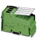
Figure 1
IB IL 24 PWR IN/PS terminal with
connectors
The terminal interrupts diagonal
routing and the bus connection and is
thus only to be used at the beginning
of an Inline station.
1
�IB IL 24 PWR IN/PS (-PAC)
U L
U S
U M
P W R IN /P S
1
1 2
Figure 2
3
4
2
1 .1
1
1
2 .1
1 .2
2
2
2 .2
1 .3
3
3
2 .3
1 .4
4
4
2 .4
6 9 4 5 A 0 0 3
IB IL 24 PWR IN/PS with appropriate connectors
Connectors 1 and 2 are not used.
Local Diagnostic Indicators
Des.
2
Color Meaning
UL
Green 7.5 V communications power
US
Green 24 V segment supply
UM
Green 24 V main supply
694500
�IB IL 24 PWR IN/PS (-PAC)
Terminal Point Assignment for Connectors 3 and 4
Terminal
Point
Connector 3
1.1, 2.1
1.2, 2.2
1.3, 2.3
1.4, 2.4
Assignment
Remark
24 V Supply for Generating UL and UANA
Not used
24 V supply for generating UL and UANA
24 V DC
U24 V
GND
GND
GND of the 24 V supply
FE
Functional Grounding of the power terminal and therefore of the Inline
earth
station.
ground
The contacts are directly connected to the potential jumper
and the FE spring on the bottom of the housing.
Functional earth ground is only used
to discharge interference.
Connector 4 Power Connector for US and UM
1.1, 2.1
24 V DC
US
24 V segment supply
The supplied voltage is directly led to the potential jumper.
24 V main supply
1.2, 2.2
24 V DC
UM
The supplied voltage is directly led to the potential jumper.
1.3, 2.3
GND
Reference The reference potential is directly led to the potential
potential
jumper and is, at the same time, ground reference for the
main and segment supply.
1.4, 2.4
FE
Functional Grounding of the power terminal and therefore of the Inline
earth
station.
ground
The contacts are directly connected to the potential jumper
and the FE spring on the bottom of the housing.
Functional earth ground is only used
to discharge interference.
Observe the current carrying capacity
The maximum total current of the potential jumpers UM and US is 8 A.
Ground the power terminal
Connect the power terminal to functional earth ground (FE) via one of the FE connections
of connector 3 or connector 4. For this, connect the corresponding contact with a
grounding terminal (see also Figure 4 on page 6).
694500
3
�IB IL 24 PWR IN/PS (-PAC)
24 V Segment Supply/24 V Main Supply
The segment supply and main supply must have the same reference potential. Therefore, an
electrically isolated voltage area on the I/O side cannot be created.
The main supply and the segment supply are protected against polarity reversal and transient surge
voltage.
Ensure short circuit protection!
The main supply and the segment supply do not have short-circuit protection.
The user must provide short-circuit protection. The rating of the preconnected fuse must
be such that the maximum permissible load current is not exceeded.
24 V Segment Supply
You can provide the segment supply at the IB IL 24 PWR IN/PS terminal or one of the supply
terminals.
There are several ways of providing the segment voltage at the IB IL 24 PWR IN/PS terminal
(connector 4):
1. You can provide the segment supply separately at terminal points 1.1 (or 2.1) and 1.3 (or 2.3)
(GND) of the power connector (Figure 4 on page 6).
2. You can jumper connections 1.1 (or 2.1) and 1.2 (or 2.2) to tap the supply for the segment circuit
from the main circuit.
3. You can insert a switch between terminal points 1.1 (or 2.1) and 1.2 (or 2.2) to create a switched
segment circuit (e.g., an emergency stop circuit).
24 V Supply for Generating UL and UANA
The 24 V supply is protected against polarity reversal and surge voltage. These protective elements
are only used to protect the power supply unit.
Ensure short circuit protection!
The 24 V supply does not have short-circuit protection.
The user must provide short-circuit protection. The rating of the preconnected fuse must
be such that the maximum permissible load current is not exceeded.
4
694500
�IB IL 24 PWR IN/PS (-PAC)
Internal Circuit Diagram
U
U
U
U L
L +
A N A
L -
U S
U M
5 V
7 ,5 V
7 ,5 V
2 4 V
1
S
+ 2 4 V (U
M
)
+ 2 4 V (U
)
6 9 4 5 A 0 0 6
Figure 3
Internal wiring of the terminal points
LED with function identification
Electrically isolated area
Converter
Diode
1
Reference potential GND
(24 V supply)
Other symbols used are explained
in the IB IL SYS PRO UM E User
Manual.
694500
5
�IB IL 24 PWR IN/PS (-PAC)
Connection Example
2
1
1
2
1
4
3
2
1
2
1
2
U
U
2 4
1
1 1
1 1
1 1
1
2
2 2
2 2
2 2
2
3
3 3
3 3
3 3
3
4
4 4
4 4
4 4
4
U
V
S
M
6 9 4 5 A 0 0 5
Figure 4
6
Typical connection of the cables to the power terminal
694500
�IB IL 24 PWR IN/PS (-PAC)
Technical Data
General Data
Order designation
Order no.
IB IL 24 PWR IN/PS
28 19 46 4
Order designation
Order no.
IB IL 24 PWR IN/PS-PAC
28 63 13 5
Housing dimensions (width x height x depth)
48.8 mm x 120 mm x 71.5 mm
(1.921 in. x 4.724 in. x 2.815 in.)
Weight
132 g (without connectors)
Permissible temperature (operation)
-25°C to +55°C (-13°F to +131°F)
Permissible temperature (storage/transport)
-25°C to +85°C (-13°F to +185°F)
Permissible humidity (operation)
75% on average, 85% occasionally
In the range from -25°C to +55°C (-13°F to +131°F) appropriate measures against
increased humidity (> 85%) must be taken.
Permissible humidity (storage/transport)
75% on average, 85% occasionally
For a short period, slight condensation may appear on the housing if, for example, the
terminal is brought into a closed room from a vehicle.
Permissible air pressure (operation)
80 kPa to 106 kPa (up to 2000 m [6562 ft.] above
sea level)
Permissible air pressure (storage/transport)
70 kPa to 106 kPa (up to 3000 m [9843 ft.] above
sea level)
Degree of protection
IP 20 according to IEC 60529
Class of protection
Class 3 according to VDE 0106, IEC 60536
Interface
Local bus
694500
Through data routing
7
�IB IL 24 PWR IN/PS (-PAC)
24 V Main Supply/24 V Segment Supply
Connection
Through power connector;
Terminal point assignment see page 3
Connection method
Spring-cage terminals
Recommended cable lengths
30 m (98.43 ft.), maximum; routing cables
through outdoor areas is not permissible
Voltage continuation
Through potential routing
Special demands on the voltage supply
When supply voltages UM/US are supplied
separately from supply voltage U24V, they are
electrically isolated from one another. This is only
possible when using two separate power supply
units.
Response when voltage dips and interrupts
occur
Voltages (main and segment supply) that are
transferred from the power terminal to the
potential jumpers follow the supply voltages
without delay.
Nominal value
24 V DC
Tolerance
-15%/+20% (according to EN 61131-2)
Ripple
± 5%
Permissible range
19.2 V to 30 V
Current carrying capacity
8 A, maximum
Safety equipment
Surge voltage
Yes
Polarity reversal
Yes
Provide an external fuse for the 24 V area
This 24 V area must be externally protected. The power supply unit must be able to
supply four times the nominal current of the external fuse, to ensure that the fuse blows
in the event of an error.
8
694500
�IB IL 24 PWR IN/PS (-PAC)
24 V Supply for Generating UL and UANA
Connection
Through connector;
Terminal point assignment see page 3
Connection method
Spring-cage terminals
Recommended cable lengths
30 m (98.43 ft.) maximum;
routing cables through outdoor areas is not
permissible
Voltage continuation
Through potential routing
Special demands on the voltage supply
When supply voltage U24V is supplied separately
from supply voltages UM/US, they are electrically
isolated from one another. This is only possible
when using two separate power supply units.
Nominal value
24 V DC
Tolerance
-15%/+20% (according to EN 61131-2)
Ripple
± 5%
Permissible range
19.2 V to 30 V
Minimum current consumption at nominal
voltage
0.012 A DC
Maximum current consumption at nominal
voltage
1.25 A DC
consisting of:
0.75 A DC for communications power
0.5 A DC for analog voltage supply
Safety equipment
Only for the 24 V supply
Surge voltage
Yes
Polarity reversal
Yes
Provide an external fuse for the 24 V area
This 24 V area must be externally protected. The power supply unit must be able to
supply four times the nominal current of the external fuse, to ensure that the fuse blows
in the event of an error.
694500
9
�IB IL 24 PWR IN/PS (-PAC)
24 V Module Supply
Communications Power (Potential Jumper)
Nominal value
7.5 V DC
Tolerance
± 5%
Ripple
± 1.5%
Maximum output current
2 A DC
Safety equipment
Electronic short-circuit protection
Analog Supply (Potential Jumper)
Nominal value
24 V DC
Tolerance
- 15% / + 20%
Ripple
± 5%
Maximum output current
0.5 A DC
Safety equipment
Electronic short-circuit protection
Power Dissipation
Formula to Calculate the Power Dissipation of the Electronics
P
E L
= (1 .1 W
A
a
x S ILn) + (0 .7 W
n = 1
A
b
x S ILm )
m
= 1
Where
PEL
Total power dissipation in the terminal
ILn
n
a
Current consumption of the device n from the communications power
Index of the number of connected devices (n = 1 to a)
Number of connected devices (supplied with communications voltage)
a
ΣIL
n = 1
Total current consumption of the devices from the 7.5 V communications power
(2 A, maximum)
n
Current consumption of the device m from the analog supply
Index of the number of connected analog devices (m = 1 to b)
Number of connected analog devices (supplied with analog voltage)
ILm
m
b
b
m
10
ΣIL
= 1
m
Total current consumption of the devices from the 24 V analog power
(0.5 A, maximum)
694500
�IB IL 24 PWR IN/PS (-PAC)
Power Dissipation (Continued)
Using the maximum currents 2 A (logic current) and 0.5 A (current for analog terminals) in the
formula to calculate the power dissipation when the I/O is connected gives the following result:
PEL = 2.2 W + 0.35 W = 2.55 W
Error Messages to the Higher-Level Control or Computer System
None
Safety Equipment
Surge voltage
(segment supply/main supply/24 V supply)
Input protective diodes (can be destroyed by
permanent overload)
Pulse loads up to 1500 W are short circuited by
the input protective diode.
Polarity reversal
(segment supply/main supply)
Parallel diodes against polarity reversal; in the
event of an error the high current through the
diodes causes the preconnected fuse to blow.
Polarity reversal
(24 V supply)
Serial diode in the lead path of the power supply
unit; in the event of an error only a low current
flows. In the event of an error the fuse in the
external power supply unit does not trip.
If you want to protect the supply U24V, use a 2 A medium blow fuse.
694500
11
�IB IL 24 PWR IN/PS (-PAC)
Electrical Isolation/Isolation of the Voltage Areas
Common Potentials
When providing the 24 V
supply for generating UL
and UANA separately from
the 24 V main supply/24 V
segment supply
Main supply and segment supply have the same potential. From the
power terminal onwards, common ground is led through the potential
jumper to the devices as reference ground GND.
When providing the 24 V
supply for generating UL
and UANA by jumpering the
24 V main supply/24 V
segment supply
Main supply, segment supply, 24 V analog supply, and 7.5 V
communications power have the same potential. From the power
terminal onwards, common ground is led through the potential jumper
to the devices as reference ground "logical GND" (UL-) for the
communications power and analog supply and separately as
reference ground GND for the supply and segment level.
24 V supply for generating UL and UANA, 24 V analog supply and 7.5 V
communications power have the same potential. From the bus
terminal onwards, common ground is led through the potential jumper
to the devices as reference ground "logical GND" (UL-).
Separate Potentials
When providing the 24 V
supply for generating UL
and UANA separately from
the 24 V main supply/24 V
segment supply
The 24 V supply for generating UL and UANA is physically and
therefore electrically isolated from the main supply and segment
supply.
When providing the 24 V
None
supply for generating UL
and UANA by jumpering the
24 V main supply/24 V
segment supply
12
694500
�IB IL 24 PWR IN/PS (-PAC)
Electrical Isolation/Isolation of the Voltage Areas
Test Distance
Test Voltage
7.5 V communications power, 24 V analog supply/
functional earth ground
500 V AC, 50 Hz, 1 min
7.5 V communications power, 24 V analog supply/
24 V main supply, 24 V segment supply
500 V AC, 50 Hz, 1 min
24 V main supply, 24 V segment supply/
functional earth ground
500 V AC, 50 Hz, 1 min
Ordering Data
Description
Order Designation
Order No.
Inline power terminal for the system voltages
UM, US, UL, UANA
including connectors and labeling fields
IB IL 24 PWR IN/PS-PAC
28 63 13 5
Inline power terminal for the system voltages
UM, US, UL, UANA
IB IL 24 PWR IN/PS
28 19 46 4
Connector set with all necessary connectors
for the terminal
IB IL PWR IN/R-PLSET
28 60 62 0
"Configuring and Installing the INTERBUS
Inline Product Range" User Manual
IB IL SYS PRO UM E
27 43 04 8
694500
13
�© Phoenix Contact 05/2003 Technical modifications reserved. TNR 90 16 16 0
IB IL 24 PWR IN/PS (-PAC)
Phoenix Contact GmbH & Co. KG
Flachsmarktstr. 8
32825 Blomberg
Germany
+ 49 - (0) 52 35 - 3-00
+ 49 - (0) 52 35 - 3-4 12 00
www.phoenixcontact.com
Worldwide Locations:
www.phoenixcontact.com/salesnetwork
14
694500
�