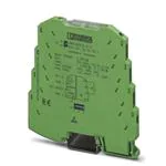
0
登录后你可以
  • 下载海量资料
  • 学习在线课程
  • 观看技术视频
  • 写文章/发帖/加入社区
创作中心
发布
  • 发文章

  • 发资料

  • 发帖

  • 提问

  • 发视频

创作活动
2864095

2864095

  • 厂商:

    PHOENIX(菲尼克斯)

  • 封装:

    -

  • 描述:

    POTIPOSITION TRANSDUCER 100-100K

  • 数据手册
  • 价格&库存
2864095 数据手册
MINI MCR-SL-R-UI... Measuring resistance/potentiometer converter INTERFACE Data sheet 102807_en_06 1 © PHOENIX CONTACT 2010-11-23 Description The 6.2 mm wide MINI MCR-SL-R-UI... potiposition transducer converts potentiometer positions as a percentage of an standard analog signal. If the potentiometer range cannot be utilized to the full, an externally accessible slide switch is used to set the upper and lower potiposition end values. The output signal between 0 and 100% is based on this fixed end value. Features – – – – Configurable potipostion transducer Output signal range can be configured using a DIP switch Approval for Ex-zone 2 (nA) Screw or spring-cage connection can be provided The DIP switches are accessible on the side of the housing and allow the following parameters to be configured: – output signal, – automatic potentiometer detection, – open circuit detection loop as well as – error indication type. Power (19.2 V DC to 30 V DC) can be supplied through connection terminal blocks on the modules or in conjunction with the DIN rail connector. Attention: Correct usage in potentially explosive areas The module is a category 3 item of electrical equipment. It is absolutely vital to follow the instructions provided here during installation and observe the information in the "Safety regulations and installation notes". Make sure you always use the latest documentation. It can be downloaded from the product at www.phoenixcontact.net/catalog. This data sheet is valid for all products listed on the following page: MINI MCR-SL-R-UI... 2 Table of contents 1 Description .............................................................................................................................. 1 2 Table of contents ..................................................................................................................... 2 3 Ordering data .......................................................................................................................... 3 4 Technical data ......................................................................................................................... 3 5 Safety regulations and installation notes.................................................................................. 5 5.1 Installation notes ................................................................................................................. 5 5.2 Installation in the Ex area (zone 2)............................................................................................ 5 6 Installation ............................................................................................................................... 6 6.1 Connection notes ................................................................................................................ 6 6.2 Structure ........................................................................................................................... 6 6.3 Block diagram ..................................................................................................................... 6 6.4 Power supply ...................................................................................................................... 6 6.5 Assembly........................................................................................................................... 7 6.6 Connecting the wires ............................................................................................................ 7 7 Configuration ........................................................................................................................... 8 7.1 Configuration tables ............................................................................................................. 9 8 Diagnostics LED ...................................................................................................................... 9 9 Teach-In ................................................................................................................................ 10 10 Connection/application example ........................................................................................... 10 102807_en_06 PHOENIX CONTACT 2 MINI MCR-SL-R-UI... 3 Ordering data Description Type Order No. Pcs./Pkt. MCR potiposition transducer for conversion of potentiometer positions into a standard analog signal, 0 Ω input... 100 Ω to 0 kΩ ... 100 kΩ MINI MCR-SL-R-UI 2864095 1 MCR potiposition transducer for converting potentiometer positions to an analog standard signal, input 0...100 Ω to 0...100 kΩ MINI MCR-SL-R-UI-SP 2810256 1 Accessories Type Order No. Pcs./Pkt. DIN rail connector (TBUS), 5-pos., for bridging the supply voltage, can be snapped onto NS 35/... DIN rails according to EN 60715 ME 6,2 TBUS-2 1,5/5-ST-3,81 GN 2869728 10 MCR power terminal block for supplying several MINI Analog modules via the DIN rail connectors, with screw connection, current consumption up to max. 2 A MINI MCR-SL-PTB 2864134 1 MCR power terminal block for supplying several MINI-ANALOG modules MINI MCR-SL-PTB-SP via the DIN rail connectors, with spring-cage connection, current consumption up to max. 2 A 2864147 1 DIN rail power supply unit, primary-switched mode, slim design, output: 24 V DC / 1.5 A MINI-SYS-PS-100-240AC/24DC/1.5 2866983 1 DIN rail power supply unit, primary-switched mode, slim design, output: 24 V DC / 1.5 A, ATEX approval MINI-PS-100-240AC/24DC/1.5/EX 2866653 1 Eight MINI analog signal converters with screw connection method can be connected to a control system using a system adapter and system cabling with a minimum of wiring and very low error risk. MINI MCR-SL-V8-FLK 16-A 2811268 1 Fold up transparent cover for MINI MCR modules with additional labeling option using insert strips and flat Zack marker strip 6.2 mm MINI MCR DKL 2308111 10 Label for extended marking of MINI MCR modules in connection with the MINI MCR-DKL MINI MCR-DKL-LABEL 2810272 10 4 Technical data Input Potentiometer resistance range 100 Ω ... 100 kΩ Reference voltage source < 3.6 V Output Voltage output signal 0 V ... 5 V 0 V ... 10 V 1 V ... 5 V 10 V ... 0 V Max. voltage output signal 12.5 V Non-load voltage Approx. 12.5 V Current output signal 0 mA ... 20 mA 4 mA ... 20 mA 20 mA ... 0 mA 20 mA ... 4 mA Max. current output signal 23 mA Short-circuit current Approx. 10 mA Load/output load voltage output > 10 kΩ Ripple < 20 mVPP (at 500 Ω) Load/output load current output < 500 Ω (20 mA) Behavior in the event of a sensor error Configurable 0 % ... 105 % 102807_en_06 PHOENIX CONTACT 3 MINI MCR-SL-R-UI... Supply Nominal supply voltage 24 V DC Supply voltage range 19.2 V DC ... 30 V DC (to bridge the supply voltage, the DIN rail connector (ME 6,2 TBUS-2 1,5/5-ST-3,81 GN, Order No. 2869728) can be used. It can be snapped onto a 35 mm DIN rail according to EN 60715) Typical current consumption < 25 mA (at 24 V DC) Power consumption < 500 mW General data Maximum transmission error < 0.2 % Maximum temperature coefficient < 0.02 %/K Step response (10-90%) < 30 ms Electrical isolation Basic insulation according to EN 61010 Surge voltage category II Mounting position Any Degree of protection IP20 Pollution degree 2 Rated insulation voltage 50 V AC/DC Test voltage, input/output/supply 1.5 kV (50 Hz, 1 min.) Dimensions W / H / D 6.2 mm / 93.1 mm / Type of housing PBT green Connection data Screw connection Spring-cage conn. Conductor cross section, solid 0.14 mm² ... 2.5 mm² 0.2 mm² ... 2.5 mm² Conductor cross section, stranded 0.2 mm² ... 2.5 mm² 0.2 mm² ... 2.5 mm² Stripping length 12 mm 8 mm Ambient conditions Ambient temperature (operation) -20 °C ... 65 °C Ambient temperature (storage/transport) -40 °C ... 85 °C Conformance with EMC Directive 2004/108/EC Noise immunity according to EN 61000-6-2 Noise emission according to EN 61000-6-4 Conformance / approvals Conformance CE-compliant ATEX  II 3 G Ex nA II T4 X UL, USA / Canada UL 508 Recognized UL, USA / Canada Class I, Div. 2, Groups A, B, C, D T5 applied for Shipbuilding GL EMC 2 D 102807_en_06 PHOENIX CONTACT 4 MINI MCR-SL-R-UI... 5 Safety regulations and installation notes 5.1 Installation notes – – – – – The device is designed for installation in zone 2 potentially explosive areas. Installation, operation, and maintenance may only be carried out by qualified electricians. Follow the installation instructions described. When installing and operating the device, the applicable regulations and safety directives (including national safety directives), as well as general technical regulations, must be observed. The technical data is provided in this package slip and on the certificates (conformity assessment, additional approvals where applicable). It is not permissible to open or modify the device. Do not repair the device yourself but replace it with an equivalent device. Repairs may only be carried out by the manufacturer. The manufacturer is not liable for damage resulting from violation. The IP20 degree of protection (EN 60529) of the device is intended for use in a clean and dry environment. Do not subject the device to any load that exceeds the described limits. The device is not designed for use in atmospheres with a danger of dust explosions. 102807_en_06 5.2 – – – – – – Installation in the Ex area (zone 2) Observe the specified conditions for use in potentially explosive areas. The device must be installed in a housing (control or distributor box) which meets the requirements of EN 6007915 and provides at least IP54 (EN 60529) degree of protection. During installation and when connecting the supply and signal circuits, observe the requirements of EN 6007914. Devices may only be connected to circuits in zone 2 if they are suitable for operation in Ex zone 2 and for the prevailing conditions at the place of use. In potentially explosive areas, terminals may only be snapped onto or off the DIN rail connector and wires may only be connected or disconnected when the power is switched off. The device must be stopped and immediately removed from the Ex area if it is damaged, has been subjected to an impermissible load, has been stored incorrectly, or if it malfunctions. You can download the latest documents for these devices from www.phoenixcontact.net/catalog. PHOENIX CONTACT 5 MINI MCR-SL-R-UI... 6.3 6 Installation 6.1 Connection notes Block diagram 1 Attention: Electrostatic discharge! 2 The device contains components that can be damaged or destroyed by electrostatic discharge. When handling the device, observe the necessary safety precautions against electrostatic discharge (ESD) according to EN 613405-1 and EN 61340-5-2. 6.2 Structure 2 3 3 DC DC 4 DC 7 UB+ 8 GND2 ME 6,2 TBUS-... Figure 2 4 5 5 OUT UI 6 GND1 mC 6.4 Block diagram Power supply ATTENTION: on S2 off 1 7 www.interface.phoenixcontact.com 6 ge: ran as. Met: Ou d: age: Loat volt mp.: Tesb. Te 5 T Am OU ,I t U Ou ND G C VD .30 ,2.. 19 1 D GN 1. 2. 3. 4. 5. 6. 7. 8. 9. 10. 11. 2 Supply via the MINI Analog Module 3 6 IN 4 7+ ER W PO 8- Where the total current consumption of the aligned modules does not exceed 400 mA, the power can be supplied directly at the connection terminal blocks of the module. 2 on off X XX XX XX .X No l ia Ser 8 S1 1 11 A 400 mA fuse should be connected upstream. Meike wars 9 Structure Input: potentiometer Cover Press/Slide button for Teach-In Diagnostics LED Groove for ZBF 6 zack marker strip Output: Standard signals Supply voltage Connection option for DIN rail connector DIP switch S1 DIP switch S2 Universal snap-on foot for EN DIN rails 102807_en_06 10 Never connect the supply voltage directly to the DIN rail connector. It is not permitted to draw power from the DIN rail connector or from individual modules. 1 8 Figure 1 1 -UI 5 L-R 09 cer u R-S 64 MC: 28 ransd V I N . T ..10 MI .-No , 0. Ord tance V sis W (1)...510 k W e R k ,0 ³ 100 mA U . °F 0... )...20 W / , 1min.+149 0(4 500 0 Hz -4°.. I £ kV , 5°C / 1,5 °..+65 -20 Supply via a power terminal block The MINI MCR-SL-PTB power terminal block (Order No. 2864134) or the MINI MCR-SL-PTB-SP power terminal block (Order No. 2864147), which are the same shape, are used to feed the supply voltage to the DIN rail connector. A 2 A fuse should be connected upstream. Supply via a system power supply unit The system power supply unit with 1.5 A output current connects the DIN rail connector to the supply voltage and can therefore be used to supply several modules from the mains. – MINI-SYS-PS-100-240AC/24DC/1.5 (Order No. 2866983) – Potentially explosive areas: MINI-PS-100-240AC/24DC/1.5/EX (Order No. 2866653) PHOENIX CONTACT 6 MINI MCR-SL-R-UI... 6.5 Assembly Screw connection: B A B A D www.interface.phoenixcontact.com C E Figure 4 • • Figure 3 – 6.6 Insert the wire into the corresponding connection terminal block. Use a screwdriver to tighten the screw in the opening above the connection terminal block. Spring-cage connection: Mount the module on a 35 mm DIN rail according to EN 60715. When using the DIN rail connector, first place it into the DIN rail (see A – C). It is used to bridge the power supply. It is also absolutely vital that you snap the module and the DIN rail connector into position in the correct direction: the snap-on foot should be at the bottom and the connector on the left. A B Connecting the wires The MINI MCR-SL-R-UI... is available in two connection variants: – Screw terminal blocks (MINI MCR-SL-R-UI) – Spring-cage terminal blocks (MINI-MCR-SL-R-UI-SP) Figure 5 • • 102807_en_06 Screw connection www.interface.phoenixcontact.com – Mounting and removing X XXX XXX o. X al N Seri X XXX XXX o. X al N Seri Spring-cage connection Insert a screwdriver into the opening above the connection terminal block. Insert the wire into the corresponding connection terminal block. PHOENIX CONTACT 7 MINI MCR-SL-R-UI... 7 Configuration If the modules are not configured (all DIP switches set to position 0), the module does not have a defined function until the DIP switches have been set. The output signal range, potentiometer/open circuit detection and fault evaluation is specified by the SP1 DIP switch. Activate automatic potentiometer detection to obtain optimum measurement results. You can use the S2 DIP switch to select the voltage and current output. www.interface.phoenixcontact.com on S2 off 1 Figure 6 ge: ran as. Met: Ou d: age: Loat volt mp.: Tesb. Te 5 T Am OU t U,I Ou D GN o. l N ria Se C D 0V .3 ,2.. 19 1 D GN -UI 5 L-R 09 cer u R-S 64 MC: 28 ransd V I ..10 MIN.-No. - T , 0. Ord tance V sis W (1)...510 k W e R k ,0 ³ 100 mA U . °F 0... )...20 W / , 1min.+149 0(4 500 0 Hz -4°.. £ I kV , 5°C / 1,5 °..+65 -20 6 S2 1 2 3 IN 4 7+ ER W PO 8- 2 on off X 1 XX X X X XX S1 8 S1 Location of the DIP switches 102807_en_06 PHOENIX CONTACT 8 MINI MCR-SL-R-UI... 7.1 Configuration tables DIP S1 Output signal range OUT 0...20 mA 20...0 mA 4...20 mA 20...4 mA 0...10 V 10...0 V 0...5 V 1...5 V 1 2 3 • • • • • • • • • • • • 7 8 A B • C • D • • DIP S2 1 2 • • • • 8 Open circuit End of measuring range +5 % End of measuring range +5 % End of measuring range +5 % Start of measuring range 4 • Automatic potentiometer detection on off 5 Open circuit detection slider • 6 on off • Measuring range overrange End of measuring range +2.5 % End of measuring range +2.5 % Measuring range underrange Start of measuring range Start of measuring range -12.5 % End of measuring range Start of measuring range End of measuring range Start of measuring range Output signal OUT 0...20 mA, 4...20 mA, 20...0 mA, 20...4 mA 0...10 V, 10...0 V, 0...5 V, 1...5 V Not allowed! • Transmission Behavior Fault evaluation in acc. with DIP 1 (7+8) Output in acc. with NE 43 Open circuit 0 mA (0 V) Linear behavior 3.8 mA ... 20.5 mA (0.95 V ... 5.12 V) Only active for 4...20 mA (1...5 V) OUT " ON " OFF Diagnostics LED The LED indicates the following error states: – LED ON: In the event of a wire break on the sensor side, measured value overrange or measured value underrange 102807_en_06 PHOENIX CONTACT 9 MINI MCR-SL-R-UI... 9 Teach-In 10 Connection/application example The "Teach-In" function serves to adjust the potentiometer Positioning table with positioner/controller range if it is not possible to use the entire range even though Lifting platform the output signal is to be fully used. The press/slide button located under the transparent cover is used for making the settings. M Setting to the lower Teach-In value ACTUAL SETPOINT 0...10V 0...10V Actuator motor Potentiometer Controller Set the potentiometer to the lowest Teach-In value and press the button downwards for approx. 1 second (towards terminal 1). If the value is saved successfully, the LED flashes once. 1 2 OUT 5 GND1 Control system 6 Setting to the upper Teach-In value Set the potentiometer to the highest Teach-In value and press the button upwards for approx. 1 second (towards terminal 5). If the value is saved successfully, the LED flashes once. 3 4 UB + GND2 7 8 MINI MCR-SL-R-UI Resetting to the lower potentiometer value 24V Mains voltage If the button is pressed downwards for more than 3 seconds Figure 8 (towards terminal 1), the lower Teach-In value is reset to the lower potentiometer value. After successful deletion of the the values, the LED flashes twice. Connection example If the button is pressed for longer that 3 seconds, both TeachIn values are reset and the full potentiometer range (0 % to 100 %) is used. Resetting to the upper potentiometer value If the button is pressed upwards for more than 3 seconds (direction of terminal 5), the upper Teach-In value is reset to the upper potentiometer value. After successful deletion of the the values, the LED flashes twice. If the button is pressed for longer that 3 seconds, both TeachIn values are reset and the full potentiometer range (0 % to 100 %) is used. 0 0% 0V 1 2 2V 0% 0V Figure 7 102807_en_06 3 4 5 6 7 8 8V 9 10 kΩ 100 % 10 V 100 % 10 V Example, determining the potentiometer range PHOENIX CONTACT GmbH & Co. KG • 32823 Blomberg • Germany • Phone: +49-(0) 5235-3-00 PHOENIX CONTACT • P.O.Box 4100 • Harrisburg • PA 17111-0100 • USA • Phone: +717-944-1300 www.phoenixcontact.com 10
2864095 价格&库存

很抱歉,暂时无法提供与“2864095”相匹配的价格&库存,您可以联系我们找货

免费人工找货