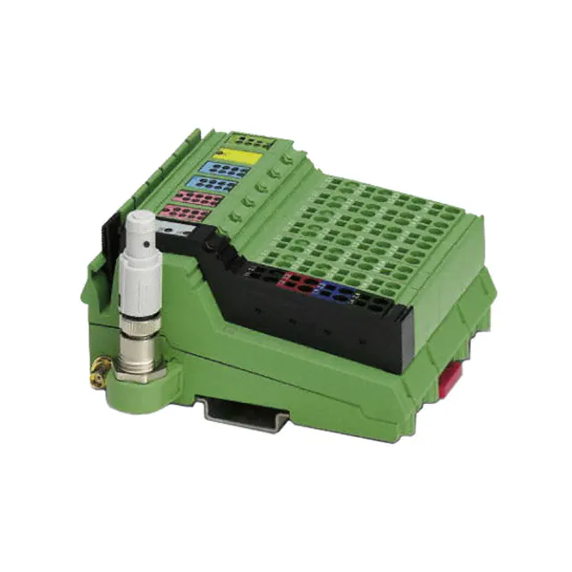
ILB BT ADIO 2/2/16/16
Bluetooth I/O Module
With 16 Digital Inputs and 16 Digital Outputs
and 2 Analog Inputs and 2 Analog Outputs
Data Sheet
7476_en_02
© PHOENIX CONTACT - 10/2007
–
in
ec
Features of Digital Inputs
–
–
–
s.
Features of Analog Inputs
–
po
Bluetooth 1.2, HID profile
Frequency range from 2.4000 GHz to 2.4835 GHz,
ISM band
The maximum emitted transmission power can be set
between 0 dBm/1 mW and 16 dBm/39.8 mW,
automatically controlled
Diagnostic and status indicators
om
–
Nominal current per output: 0.5 A
Total current of all outputs: 8 A
Short-circuit and overload protected outputs
Status indicators
ne
Features of the Radio Interface
–
–
–
–
nt
The ILB BT ADIO 2/2/16/16 module is used to acquire and
output digital and analog signals. It uses wireless
transmission to send 16 digital and two analog input and
output signals to the relevant Bluetooth base station.
co
Description
–
–
m
AUTOMATIONWORX
Connections for 16 digital sensors
Connection of sensors in single-wire technology
Status indicators
–
–
–
Two analog single-ended signal inputs for the
connection of either voltage or current signals
Connection of sensors in 2 and 3-wire technology
Current measuring range of 0 mA to 20 mA
Voltage measuring range of 0 V to 10 V
Features of Analog Outputs
–
–
–
–
Two analog single-ended signal outputs for the
connection of either voltage or current signals
Connection of actuators in 2 and 3-wire technology
Current measuring range of 0 mA to 20 mA
Voltage measuring range of 0 V to 10 V
–
–
on
l
Features of Digital Outputs
Connections for 16 digital actuators
Connection of actuators in single-wire technology
Make sure you always use the latest documentation.
It can be downloaded at www.download.phoenixcontact.com.
A conversion table is available on the Internet at
www.download.phoenixcontact.com/general/7000_en_00.pdf.
Please refer to the application note for instructions on how to assemble/remove the module.
�ILB BT ADIO 2/2/16/16
Usage Notes
The wireless system complies with the basic
requirements and other relevant regulations
specified in directive 1999/5/EU.
This device contains:
FCC ID: PVH071902
IC: 5325A-0719X
co
s.
nt
ne
om
po
The ILB BT ADIO 2/2/16/16 module must only
be operated in the following countries:
Austria, Belgium, Bulgaria, Canada, Cyprus,
Czech Republic, Denmark, Estonia, Finland,
France, Germany, Great Britain, Greece,
Hungary, Iceland, Ireland, Italy, Latvia,
Lithuania, Luxembourg, Malta, the
Netherlands, Norway (not including
Spitzbergen), Poland, Portugal, Romania,
Slovakia, Slovenia, Spain, Sweden,
Switzerland, USA*)
m
This device complies with Part 15 of the FCC Rules.
Operation is subject to the following two conditions:
(1) this device may not cause harmful interference, and (2)
this device must accept any interference received,
including interference that may cause undesired
operations.
in
ec
*) In outdoor installations, the device may only
be operated with an emitted power of 10 dBm
maximum from the antenna
on
l
Please note the maximum permissible emitted
transmission power for the country of use.
The use of products described in this data
sheet is oriented exclusively to qualified
electricians or persons instructed by them, who
are familiar with applicable national standards
and other regulations regarding electrical
engineering and, in particular, the relevant
safety concepts.
Phoenix Contact accepts no liability for
erroneous handling or damage to products
from Phoenix Contact or third-party products
resulting from disregard of information
contained in this data sheet.
7476_en_02
PHOENIX CONTACT
2
�ILB BT ADIO 2/2/16/16
Transmission Power
Depending on the maximum possible transmission power,
the operation of this device must be notified or approved in
some countries. Occasionally, usage restrictions may apply
for the transmission power for indoor or outdoor use.
m
Before device startup, the maximum permissible
transmission power must be set (default upon delivery:
16 dBm). The antenna gain of the antenna used should be
taken into account. For the antenna provided (gain 0 dBi),
the transmission power values printed on the device apply.
The maximum transmission power is set using DIP
switches on the rear of the device.
To apply the transmission power setting, restart the device.
ne
nt
s.
co
MODE
16
dBm
12
dBm
8
dBm
4
dBm
0
dBm
DIP switches for setting the transmission
power
on
l
in
ec
Figure 1
om
po
DIP
7476_en_02
PHOENIX CONTACT
3
�ILB BT ADIO 2/2/16/16
Ordering Data
Module
Description
Type
Order No.
Pcs./Pck.
Bluetooth I/O module with 16 digital inputs and 16 digital outputs and two
analog inputs and two analog outputs
ILB BT ADIO 2/2/16/16
2884282
1 set
FLM BT BS3 M12
2736770
1
FL BT MOD IO AP
2884758
1
Accessories
Connectors as Replacement Item
Type
Order No.
Pcs./Pck.
Shield connector
IB IL SCN-6 SHIELD-TWIN
2740245
5
Connector for the supply (with color print)
IB IL SCN-PWR IN-CP
2727637
10
Connector for input and output terminals
IB IL SCN-8
2726337
10
m
Fieldline Modular Bluetooth base station
Factory Line Bluetooth base station
co
Antennas
RAD-ISM-2400-ANT-PAN-8-0
2867610
1
Pigtail antenna cable for panel antenna
RAD-PIG-EF-316-SMA-SMA
2885618
1
Omnidirectional antenna with protection against vandalism
RAD-ISM-2400-ANT-VAN-3-0-SMA
2885867
1
3022276
50
s.
Panel antenna
nt
Only use approved accessories.
ne
Additional Accessories
Recommended end clamp; placed to the right of the module
to secure it on the DIN rail
CLIPFIX 35-5
on
l
in
ec
om
po
Accessories for extending the antenna cable are available on request.
7476_en_02
PHOENIX CONTACT
4
�ILB BT ADIO 2/2/16/16
Technical Data
General Data
Housing dimensions with connectors (width x height x depth)
117 mm x 73 mm x 121 mm
Weight (without antenna)
305 g (with connectors, ID plug, and antenna)
Connection method for sensors and actuators
Single-wire technology
Housing Dimensions
73
57
in
ec
om
po
ne
121
nt
s.
co
m
117
7476A002
Figure 2
Housing dimensions of the module (mm)
Ambient Conditions
Regulations
Ambient temperature (operation)
Developed according to VDE 0160, UL 508
-25°C to +60°C
-25°C to +85°C
Humidity (operation)
75% on average, 85% occasionally, no condensation
on
l
Ambient temperature (storage/transport)
In the range from -25°C to +60°C appropriate measures against increased humidity (> 85%) must be taken.
Humidity (storage/transport)
95%
For a short period, slight condensation may appear on the outside of the housing if, for example, the module is brought into a closed room
from a vehicle.
Air pressure (operation)
80 kPa to 108 kPa (up to 2000 m above sea level)
Air pressure (storage/transport)
66 kPa to 108 kPa (up to 3500 m above sea level)
Degree of protection according to DIN 40050, IEC 60529
IP20
Protection class according to EN 61131-2, IEC 61131-2
3
Air and creepage distances
According to IEC 60664/IEC 60664A DIN VDE 0110: 1989-01 and
DIN VDE 0160: 1988-05
7476_en_02
PHOENIX CONTACT
5
�ILB BT ADIO 2/2/16/16
Ambient Conditions (Continued)
Housing material
Plastic, PVC-free, PBT, self-extinguishing (V0)
Pollution degree according to EN 60664, EN 61131-2
2; condensation not permitted during operation
Surge voltage class
II
Electrical Isolation/Isolation of the Voltage Areas
Common Potentials
24 V communications power, 24 V actuator supply, and GND have the same potential. FE is a separate potential area.
- Test Distance
- Test Voltage
500 V AC, 50 Hz, 1 min.
24 V supply (I/O)/analog channels
500 V AC, 50 Hz, 1 min.
Analog channels/FE
500 V AC, 50 Hz, 1 min.
m
24 V supply (I/O)/functional earth ground
Mechanical Requirements
5g load, 2.5 hours in each space direction
Shock test according to IEC 60068-2-27; EN 60068-2-27
25g load for 11 ms, half sinusoidal wave,
3 shocks in each space direction and orientation
Broadband noise according to IEC 60068-2-64; EN 60068-2-64
0.78g load, 2.5 hours in each space direction
s.
co
Vibration test sinusoidal vibrations according to IEC 60068-2-29;
EN 60068-2-29
EN 61000-4-3
IEC 61000-4-3
Fast transients (burst)
EN 61000-4-4/
IEC 61000-4-4
6 kV contact discharge
8 kV air discharge
om
Electromagnetic fields
Criterion B
ne
EN 61000-4-2
IEC 61000-4-2
EN 61000-4-5
IEC 61000-4-5
EN 61000-4-6
IEC 61000-4-6
on
l
Conducted interference
in
ec
Surge voltage
Criterion A
po
Electrostatic discharge (ESD)
nt
Conformance With EMC Directive 89/336/EEC
Noise Immunity Test According to EN 61000-6-2
Field strength: 10 V/m
Criterion B
Remote bus: 2 kV
Power supply: 2 kV
I/O cables: 2 kV
Criterion A
All interfaces: 1 kV
Criterion B
DC supply lines: ±0.5 kV/±0.5 kV
(symmetrical/asymmetrical)
Signal cables: ±0.5 kV/±0.5 kV
(symmetrical/asymmetrical)
Criterion A
Test voltage 10 V
Noise Emission Test According to EN 61000-6-4
Noise emission of housing
EN 55011
Class A (industrial applications)
Test for Radio Approval
EMC
ETSI EN 301 489-17
Radio
ETSI EN 300 328
Safety
EN 60950-1
Health
EN 50371
Radio Interface
Radio interface
Bluetooth 1.2
Frequency range
2.4000 GHz to 2.4835 GHz
Channel distance
1 MHz
Number of channels
79
7476_en_02
PHOENIX CONTACT
6
�ILB BT ADIO 2/2/16/16
Radio Interface (Continued)
Modulation
GFSK (Gaussian Frequency Shift Keying)
Maximum transmission power at the antenna connection
Can be set between 0 dBm/1 mW and 16 dBm/39.8 mW in 4 dB increments
Antenna connection
SMA female connector
24 V Module Supply
Communications Power
Nominal value
24 V DC
-15%/+20% according to EN 61131-2
Ripple
±5% according to EN 61131-2
19.2 V ... 30.0 V
Current consumption at UL
75 mA
Protection against polarity reversal
Yes
Surge protection
Yes
Connection
Via power connectors
co
Permissible range
m
Tolerance
Actuator Supply
24 V DC
Tolerance
-15%/+20% according to EN 61131-2
s.
Nominal value
±5% according to EN 61131-2
Permissible range
19.2 V ... 30.0 V
Current consumption at UL
8 A, maximum
1
Overload protection
Yes
ne
Number of isolated groups
Protection against polarity reversal
No
Via power connectors
po
Connection
Digital Outputs
16
Number of voltage groups
Connection method for actuators
Nominal output voltage UOUT
Differential voltage for Inom
in
ec
Nominal current Inom per channel
Total current
Protection
Nominal load
on
l
Ohmic
Inductive
om
Number
Lamp
nt
Ripple
1
Single-wire technology
24 V DC
≤1V
0.5 A
8A
Short circuit; overload
48 Ω/12 W
12 W
12 VA (1.2 H, 50 Ω)
Switching frequency with nominal inductive load
0.5 Hz (1.2 H, 50 Ω)
Overload response
Auto restart
Response with inductive overload
Output may be damaged
Reverse voltage protection against short pulses
Yes
Resistance to permanently applied reverse voltages
Yes, maximum permissible current 2 A
Response upon power down
The output follows the supply voltage without delay.
Limitation of the voltage induced on circuit interruption
-41 V
Single maximum energy in free running
1 J, maximum
Protective circuit type
Integrated free running circuit in the output chip
Overcurrent shutdown
0.7 A, minimum
Maximum output current when switched off
10 µA
When not loaded, a voltage can be measured even at an output that is not set.
7476_en_02
PHOENIX CONTACT
7
�ILB BT ADIO 2/2/16/16
Digital Inputs
Number
16
Connection method for sensors
Single-wire technology
Input design
According to EN 61131-2 Type 1
Definition of switching thresholds
Maximum low-level voltage
ULmax < 5 V
Minimum high-level voltage
UHmin > 15 V
Common potentials
Ground
Nominal input voltage UIN
24 V DC
-30 V < UIN < +30 V DC
Nominal input current for UIN
3.6 mA per channel, typical
Current flow
Linear in the range 1 V < UIN < 30 V
Delay time
≤ 300 µs
m
Permissible range
100 m
Use of AC sensors
AC sensors in the voltage range < UIN are limited in application
co
Permissible cable length to the sensor
Typical Power Dissipation With 24 V Supply Voltage
16
2
16
2
m=0
l=0
s.
Formula to calculate the power dissipation of the electronics
2
po
Total power dissipation of the module
Index of the number of set digital outputs (n = 0 to 16)
Load current of output n
Index of the number of set digital inputs (m = 0 to 16)
Index of the number of analog outputs used (I = 0 to 2)
Index of the number of analog inputs used (k = 0 to 2)
Simultaneity, Derating
No limitation of simultaneity, derating
-25°C ... +50°C
Total Current (ITOT)
8A
A
8 A - ((TA - 50°C) x 0.4 A/°C)
on
l
+50°C ... +60°C
in
ec
Output Derating
Ambient Temperature (TA)
om
Where
PTOT
n
ILn
m
I
k
k=0
ne
n=0
nt
PTOT = 0.552 W + S (0.065 W + ILn x 0.28 W) + S 0.086 W + S 0.372 W + S 0.044 W
8
IT
O T
4
0
-2 5
7 1 7 3 A 0 0 7
7476_en_02
0
5 0
T
6 0
° C
A
PHOENIX CONTACT
8
�ILB BT ADIO 2/2/16/16
Analog Outputs
Number
2
Signals/resolution
0 V ... 10 V voltage
2.44 mV
0 mA ... 20 mA current
4.88 µA
Output load
Voltage output
2 kΩ, minimum
Current output
0 Ω ... 500 Ω
Representation of Output Values
4
3
2
1
LSB
0
co
Representation of output values
MSB
15 14 13 12 11 10 9 8 7 6 5
SB
Analog value
m
The output value is represented in bits 14 to 0. An additional bit (bit 15) is available as a sign bit.
s.
7476b006
Significant Output Values
nt
Output range 0 mA to 20 mA and 0 V to 10 V
0 mA to 20 mA
IOutput
dec
≤32767
7530
30000
0001
32512
1
Safety Equipment
0 V to 10 V
UOutput
mA
V
+21.6746
+10.837
+21.6746
+10.837
+20.0
+10.0
+0.66667 µA
+333.33 µV
0
0
0
in
ec
0000
po
hex
≤FFFF
≤7F00
om
ne
Output Data Word
(Two's Complement)
Transient protection at voltage and current outputs
Tolerance and Temperature Response of Analog Outputs
The tolerance values refer to the measuring range final value.
on
l
Tolerances at TA = +23°C
Measuring Range
Absolute (Typical)
Absolute (Maximum)
Relative (Typical)
0 V ... 10 V
±31 mV
±93 mV
±0.31%
Relative (Maximum)
±0.93%
0 mA ... 20 mA
±112 µA
±194 µA
±0.56%
±0.97%
Temperature and Drift Response (TA = -25°C to +60°C)
Drift in reference to the measuring range final value.
Measuring Range
Typical
0 V ... 10 V
306 ppm/K
750 ppm/K
0 mA ... 20 mA
306 ppm/K
740 ppm/K
7476_en_02
Maximum
PHOENIX CONTACT
9
�ILB BT ADIO 2/2/16/16
Analog Inputs
Voltage Inputs
Input resistance
> 150 kΩ
Limit frequency (-3 dB) of the input filters
40 Hz
Maximum permissible voltage between analog voltage inputs and analog
reference potential
±32 V
Common mode rejection (CMR)
103 dB
Permissible DC common mode voltage for CMR
40 V between voltage input and FE
Current Inputs
110 Ω (shunt)
Input resistance
40 Hz
Maximum permissible voltage between analog current inputs and analog
reference potential
±32 V (the input voltage is limited internally)
m
Limit frequency (-3 dB) of the input filters
103 dB
Permissible DC common mode voltage for CMR
40 V between current input and FE
Maximum permissible current
Internally limited by protective circuit
co
Common mode rejection (CMR)
s.
Safety Equipment
Suppressor diodes in the analog inputs,
current limitation via internal protective circuit
nt
Surge voltage
Tolerance and Temperature Response of Analog Inputs
ne
The tolerance values refer to the measuring range final value.
Tolerances at TA = +23°C
Measuring Range
Absolute (Typical)
±30 mV
0 mA ... 20 mA
±80 µA
Absolute (Maximum)
Relative (Typical)
Relative (Maximum)
±74 mV
±0.30%
±0.74%
±164 µA
±0.40%
±0.82%
po
0 V ... 10 V
om
Temperature and Drift Response (TA = -25°C to +60°C)
Drift in reference to the measuring range final value
Measuring Range
in
ec
0 V ... 10 V
0 mA ... 20 mA
Typical
Maximum
40 ppm/K
170 ppm/K
40 ppm/K
175 ppm/K
Additional Tolerances Influenced by Electromagnetic Fields
Typical Deviation of the Measuring Range Final Value
(Voltage and Current Channels)
on
l
Type of Electromagnetic Interference
Relative
Electromagnetic fields; field strength 10 V/m
according to EN 61000-4-3/IEC 61000-4-3
< ±0.5%
Conducted interference, Class 3 (10 V test voltage)
according to EN 61000-4-6/IEC 61000-4-6
< ±0.5%
Fast transients (burst); 4 kV supply, 2 kV input
according to EN 61000-4-4/IEC 61000-4-4
< ±0.5%
Representation of Input Values
The output value is represented in bits 14 to 0. An additional bit (bit 15) is available as a sign bit. This format supports
extended diagnostics. Values > 8000hex indicate an error.
Representation of input values
MSB
15 14 13 12 11 10 9 8 7 6 5
SB
Analog value
4
3
2
LSB
1 0
7476b006
7476_en_02
PHOENIX CONTACT
10
�ILB BT ADIO 2/2/16/16
Significant Measured Values
Output range 0 mA to 20 mA and 0 V to 10 V
Input Data Word
(Two's Complement)
0 mA to 20 mA
IInput
0 V to 10 V
UInput
hex
dec
mA
V
Overrange
> +21.6746
> +10.837
32512
+21.6746
+10.837
7530
30000
+20.0
+10.0
0001
1
+0.66667 µA
+333.33 µV
0000
0
0
0
m
8001
7F00
LINK
AI2
QUALITY
nt
AO2
FS
IDPLUG
s.
co
Local Diagnostic and Status Indicators
UA
AI2
K ITY
LINAL
QU
AO
2
FS
IDUG
PL
DI16
BLUETOOTH
PW
R1
UA
DI16
UL
2
4
6
8
E
9
11
13
15
10
12
14
16
2
4
6
8
in
ec
1
3
5
7
DO
16
9
11
13
15
om
E
1
3
5
7
po
DO
16
UL
10
12
14
16
7476A003
Diagnostic and status indicators of the module
on
l
Figure 3
ne
PWR1
Designation
PWR
LED Color
Meaning
UA
Green
24 V actuator supply
UL
Green
24 V communications power
E
Red
1 to 16
Yellow
Status indicators for the outputs
1 to 16
Yellow
Status indicators for the inputs
FS
Red
OUT
Short circuit or overload at one of the outputs
IN
FS
7476_en_02
Failsafe, analog and digital outputs set to 0
PHOENIX CONTACT
11
�ILB BT ADIO 2/2/16/16
Designation
LED Color
Meaning
ID-PLUG
ID
Green/yellow/ ID plug status (normal operation)
red
Green ON
ID plug was read successfully
Yellow ON
Reading ID plug
Red ON
OFF
ID plug cannot be read
ID plug not present
Green/yellow/ ID plug status (clear mode/Bluetooth network login)
red
Yellow ON
Ready to clear/program the ID plug
LQ
s.
LINK QUALITY
co
Green flashing Ready for Bluetooth network login
m
Attention/caution
Please refer to the "Clearing and Reprogramming Function" section.
Quality of the Bluetooth connection (bit error rate; BER)
nt
4 green LEDs BER 0% - 0.05%
2 green LEDs BER 0.1% - 1.7%
ne
3 green LEDs BER 0.05% - 0.1%
BER > 1.7%
4 LEDs OFF
No Bluetooth connection established
po
1 green LED
on
l
in
ec
om
If the error LED (E) of a group of 16 outputs lights up (e.g., connector 2 and connector 3), this indicates that a
short circuit or overload is present at one or more of the outputs in this group.
7476_en_02
PHOENIX CONTACT
12
�ILB BT ADIO 2/2/16/16
Connecting the Supply, Actuators, and Sensors
2-7
1
1
1.1
1.2
2
2.1
1
1.3
1
1
1
2
2
3
ITY
LINK
AL
QU
1.2
2
2
2
2.1
1.1
1
The terminal points for GND and UL can have
a total current of 8 A per terminal point. The
maximum current carrying capacity of 8 A must
not be exceeded.
AI2
3
2.2
The supply points have the same ground
potential. All ground supplies on a module are
electrically connected with one another.
The communications power is also electrically
connected via all contacts. In this way, it can
supply all potentials with just one supply
without the need for additional terminals, see
"Connection example for the supply" on
page 15.
2.3
2
AO
2.2
FS
1.4
4
4
2.4
2.4
UL
co
4
DO
16
R1
PW
UA
s.
4
3
BLUETOOTH
1.4
3
2.3
m
DI16
1.3
Terminal Point Assignment of the Power Connector
nt
po
Terminal point assignment of the connectors
ne
7476A004
Figure 4
Terminal Point
Assignment
Connector 1 (PWR)
1.1, 2.1
24 V actuator supply UA
1.2, 2.2
24 V communications power UL
1.3, 2.3
GND
1.4, 2.4
FE
Connector 2 (OUT1)
om
Terminal Point Assignment of the Digital Output and Input Connectors
Q9
2.1
Q10
1.1
I1
2.1
I2
1.1
I9
2.1
I10
Q11
2.2
Q12
1.2
I3
2.2
I4
1.2
I11
2.2
I12
Q13
2.3
Q14
1.3
I5
2.3
I6
1.3
I13
2.3
I14
Q15
2.4
Q16
1.4
I7
2.4
I8
1.4
I15
2.4
I16
Connector 3 (OUT2)
Q1
2.1
Q2
1.1
1.2
Q3
2.2
Q4
1.2
1.3
Q5
2.3
Q6
1.3
1.4
Q7
2.4
Q8
1.4
in
ec
1.1
Connector 4 (IN1)
Connector 5 (IN2)
1.1
on
l
Terminal Point Assignment of the Analog Output Connector
Connector 6 (Analog OUT)
+U1, voltage output channel 1
2.1
+U2, voltage output channel 2
1.2
+I1, current output channel 1
2.2
+I2, current output channel 2
1.3
AGND, analog ground
2.3
AGND, analog ground
1.4
Shield connection
2.4
Shield connection
Terminal Point Assignment of the Analog Input Connector
Connector 7 (Analog IN)
1.1
+U1, voltage input channel 1
2.1
+U2, voltage input channel 2
1.2
+I1, current input channel 1
2.2
+I2, current input channel 2
1.3
AGND, analog ground
2.3
AGND, analog ground
1.4
Shield connection
2.4
Shield connection
7476_en_02
PHOENIX CONTACT
13
�ILB BT ADIO 2/2/16/16
Internal Basic Circuit Diagram
UL
FS
ID plus
Antenna
ID plug
BT
Transmission
power
24 V UL
3.3 V DC
Shift
register
Shift
register
IN
OUT
Link
quality
nt
s.
15 V DC
co
24 V DC
m
board
24 V DC
IN
1...16
OUT
1...16
UA
Analog
Analog
IN1...2
in
ec
OUT1...2
Digital
IN1...16
24 V UA
7476b005
Digital
OUT1...16
Internal wiring of the terminal points
on
l
Figure 5
om
po
ne
E
Key:
x x x
X X X
Power supply unit with electrical
isolation
Optocoupler
Input filter
Output driver
7476_en_02
PHOENIX CONTACT
14
�ILB BT ADIO 2/2/16/16
Connection Example
The numbers above the module illustration indicate the connector slots.
UL
4
5
6
7
+
-
co
+
-
3
IN 6
om
OUT 4
po
ne
nt
s.
UA
2
m
1
OUT
OUT
IN
IN
24V
C
D
Connection example for the supply
Key:
on
l
in
ec
Figure 6
A:
B:
B
A
Actuator at the voltage output (channel 1)
Actuator at the current output (channel 2)
7476A006
C:
D:
Active sensor with current output (channel 1)
Active sensor with voltage output (channel 2)
Startup With the Fieldline Base Station (Observe Compatibility Table)
The ID plug is programmed on the base station. For additional information, refer to the data sheet for the
FLM BT BS 3 base station.
To operate the module, the base station must be Version 01/1.20/1.10 (hardware/firmware/firmware) or later.
•
•
Plug in the programmed ID plug before switching on
the module.
Switch on the supply voltage. The connection data is
then read from the ID plug.
7476_en_02
•
•
The module connects automatically to the base station
programmed on the ID plug.
Once the connection has been established (FS LED
goes off), process data is exchanged cyclically
between the base station and the module.
PHOENIX CONTACT
15
�ILB BT ADIO 2/2/16/16
Startup With the Factory Line Base Station
•
•
Please observe the compatibility table.
Plug in the ID plug provided before switching on the
I/O device.
•
Switch on the supply voltage; Bluetooth login is started.
If the ID plug is already programmed, connection data
is read from the ID plug.
Following connection establishment, the
ID plug is programmed by the base station via
the IO device. For additional information, refer
to the data sheet for the FL BT MOD IO AP.
co
s.
nt
•
If the Factory Line base station has to be replaced in
the existing Bluetooth network, the ID plug should be
reprogrammed for Bluetooth network login.
Remove the ID plug from the IO device and switch on
the power supply. The ID LED flashes yellow for
around 10 seconds. Plug in the ID plug during this time.
The ID plug is cleared and reprogrammed. The ID LED
flashes green to indicate successful programming. The
IO device is ready again for Bluetooth network login.
ne
•
m
Clearing and Reprogramming Function
po
Attention
on
l
in
ec
om
As a rule, if the ID plug is not inserted in the
IO device when the power supply is switched
on, the clearing and reprogramming function
will start briefly. If an ID plug is inserted during
this time, it will be cleared and reprogrammed
for Bluetooth network login mode. Any previous
connection data will be lost.
7476_en_02
PHOENIX CONTACT
16
�ILB BT ADIO 2/2/16/16
Compatibility Table
Fieldline Modular Bluetooth Base Station
Base Station
IO Device
FLM BT BS3 M12
Version
Hardware/Firmware/
Firmware
ILB BT ADIO 2-2-16-16
Version
Hardware/Firmware
Compatibility
00/1.10/1.10
00/1.00
No
01/2.00
No
01/1.20/1.10
00/1.00
Yes, with limited
IO device functions
and diagnostics
01/2.00
No
01/1.30/2.00
00/1.00
Yes
01/2.00
Yes
co
00/1.00
s.
No
01/1.10/1.10
m
No
01/2.00
Factory Line Bluetooth Base Station
1.0/1.xx
00/1.00
No
01/2.00
Yes
nt
Compatibility
ne
IO Device
ILB BT ADIO 2-2-16-16
Version
Hardware/Firmware
on
l
in
ec
om
po
Base Station
FL BT MOD IO AP
Version
Hardware/Firmware
7476_en_02
PHOENIX CONTACT
17
�ILB BT ADIO 2/2/16/16
Process Data
The module process data is integrated into the process data of the base station.
11
10
Word 3
9
8
7
Analog channel 1
6
Bit
Assignment
16
15
14
13
12
11
10
Word 4
9
8
7
Analog channel 2
12
11
10
4
3
2
1
s.
5
4
3
2
1
7
6
5
4
3
2
1
nt
6
OUT 3
OUT 2
OUT 1
6
5
4
3
2
1
11
Word 4
10
9
8
7
Analog channel 2
12
6
5
4
3
2
1
OUT 8
OUT 4
12
ne
11
Word 3
10
9
8
7
Analog channel 1
OUT 9
OUT 5
13
OUT 6
14
13
OUT 7
15
14
po
OUT 13
15
Word 2
9
8
OUT 10
OUT 14
16
5
OUT 11
OUT 15
16
OUT 12
13
om
14
in
ec
Bit
Assignment
15
on
l
Bit
Assignment
16
OUT 16
Output Process Image
Bit
Assignment
1
OUT 1
12
2
OUT 2
13
3
OUT 3
14
4
co
15
OUT 8
16
OUT 9
Bit
Assignment
5
OUT 4
6
m
7
OUT 6
Word 2
9
8
OUT 7
10
OUT 10
11
OUT 11
12
OUT 12
13
OUT 13
14
OUT 14
15
OUT 15
16
OUT 16
Bit
Assignment
OUT 5
Input Process Image
Diagnostics
Error Table With Status Display
Error Type
Communications power UL too low
Sensor supply UA too low
Short circuit/overload of a digital
output
Wireless connection aborted
7476_en_02
Diagnostic Data
None
None
I/O error message
Status Indicators
UL LED is OFF.
UA LED is OFF.
E LED of the affected output group lights up red.
I/O error message
FS LED is ON.
PHOENIX CONTACT
18
�ILB BT ADIO 2/2/16/16
Antennas
The aim of Phoenix Contact wireless transmission solutions
is to provide users with the simplest possible access to the
"wireless" transmission medium.
This explanation of the complex area of antenna
technology will therefore be kept as simple as possible.
However, in order to build reliable systems, a few basic
features of antenna technology must be taken into account.
Antenna Alignment
Figure 7
co
s.
nt
Fresnel zone adversely affected by the terrain
Figure 9
Fresnel zone adversely affected by obstacles
Figure 10
Radius R of the Fresnel zone over distance D
po
In Figure 8, the Fresnel zone is adversely affected by the
terrain. With the antenna masts at this low level, although
there is still a line of sight, the Fresnel zone is not
completely clear.
Figure 8
ne
The Fresnel zone, which extends around the direct
connecting line between transmitting and receiving
antennas should also be taken into account. If this zone is
disturbed by obstacles or the terrain, this will adversely
affect the wireless connection.
Figure 7 illustrates an ideal installation with undisturbed
connection.
Ideal antenna installation
m
When installing two antennas, it is generally desirable to
have a line of sight between them wherever possible, as
any obstacles between the antennas will adversely affect
the connection.
om
In Figure 9, the connection is attenuated by obstacles in the
Fresnel zone, even though there is a line of sight.
in
ec
The radius of the Fresnel zone depends on the
transmission frequency and the distance between the
transmitting and receiving antennas.
on
l
The radius R corresponds to the minimum height of the
antenna mast (if the terrain is level). For a 2.4 GHz system,
the mast height R/m, depending on the distance to be
covered D/m, is given in the characteristic curve in
Figure 10.
Example (Figure 10):
For a distance of 100 m, the antenna should be installed at
a minimum height of 1.80 m to provide a clear Fresnel zone.
© PHOENIX CONTACT 10/2007
7476_en_02
PHOENIX CONTACT GmbH & Co. KG • 32823 Blomberg • Germany
Phone: +49 - 52 35 - 30 0 • Fax: +49 - 52 35 - 34 12 00
www.phoenixcontact.com
19
�s.
nt
ne
po
om
in
ec
on
l
co
m
�