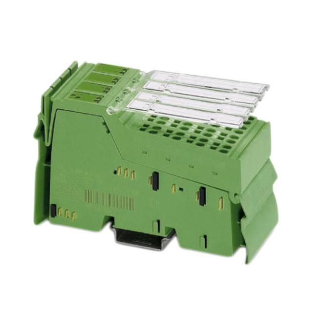
IB IL TEMP 4/8 RTD/EF ...
Inline terminal with eight analog input channels
for the connection of resistive temperature
detectors (RTD)
Data sheet
7567_en_07
1
© PHOENIX CONTACT 2012-07-07
Function description
The terminal is designed for use within an Inline station. This
terminal provides an 8-channel input module with three
linear resistance ranges for resistance temperature
detectors.
This terminal supports, for example:
– Platinum and nickel sensors, e.g., Pt100, Pt1000,
Ni100, and Ni1000 according to the DIN IEC 60751
standard and to the SAMA RC 21-4-1966 guideline
– KTY81 and KTY84 sensors
– Cu10, Cu50, and Cu53 sensors
Communication either via
– Parameter channel (PCP), all eight measuring
channels, or
– Four process data words; always four channels
(four 16-bit values) using the multiplex method
–
–
–
–
–
–
–
–
Features
–
–
–
High-resolution temperature and resistance
measurement
Resistance values (R0) can be preset separately using
configuration bits
Channels are configured independently of one another
using the bus system
Configuring the open circuit detection sensitivity (firmware 1.10 or later)
Additional representation in float format according to
IEEE 754
Diagnostic and status indicators
Channel scout functionality, e.g., for optical channel
identification during startup
IB IL TEMP 4/8 RTD/EF-PAC,
IB IL TEMP 4/8 RTD/EF:
Hardware version 02 or later:
IB IL TEMP 4/8 RTD/EF 2MBD-PAC
Hardware version 01 or later:
Approved for use in zone 2 potentially explosive areas
(observe the notes on page 12)
Connection of eight RTD temperature sensors and
linear resistors in 4-wire technology
High precision and noise immunity
Temperature stability
This data sheet only is valid in connection with the IL SYS INST UM E user manual
(see “Documentation” on page 3).
Make sure you always use the latest documentation.
It can be downloaded at www.phoenixcontact.net/catalog.
This data sheet is valid for all products listed on page 3.
�IB IL TEMP 4/8 RTD/EF ...
Table of contents
1
Function description ................................................................................................................... 1
2
Ordering data.............................................................................................................................. 3
3
Technical data ............................................................................................................................ 4
4
Internal circuit diagram................................................................................................................ 9
5
Local diagnostic and status indicators and terminal point assignment.......................................10
6
Safety notes...............................................................................................................................10
7
Installation instructions ..............................................................................................................10
8
Electrical isolation ......................................................................................................................11
9
Connection notes.......................................................................................................................11
10 Notes on using the terminal in potentially explosive areas .........................................................12
11 Connection examples ................................................................................................................13
12 Programming data/configuration data........................................................................................14
13 Process data..............................................................................................................................15
14 Process data output words OUT ................................................................................................15
15 Process data input words IN ......................................................................................................19
16 Formats for representing measured values................................................................................20
17 PCP communication ..................................................................................................................22
18 Object descriptions ....................................................................................................................22
19 Configuration and analog values................................................................................................27
20 Temperature and resistance measuring ranges.........................................................................27
21 Measuring errors due to connection cables ...............................................................................27
22 Calculation examples ......................................................................................................................................... 29
23 Configuration example...............................................................................................................31
24 Notes on diagnostic behavior in the event of an error ................................................................33
7567_en_07
PHOENIX CONTACT
2
�IB IL TEMP 4/8 RTD/EF ...
2
Ordering data
Products
Description
Type
Order No.
Pcs./Pkt.
Inline terminal for resistive temperature detectors, without accessories,
transmission speed: 500 kbps
IB IL TEMP 4/8 RTD/EF
2897305
1
Inline terminal for resistive temperature detectors,
complete with accessories (connectors and labeling fields)
transmission speed: 500 kbps
IB IL TEMP 4/8 RTD/EF-PAC
2897402
1
Inline terminal for resistive temperature detectors,
complete with accessories (connectors and labeling fields)
transmission speed: 2 Mbps
IB IL TEMP 4/8 RTD/EF 2MBD-PAC
2897606
1
Four of the connectors listed below are needed for the fitting of the IB IL TEMP 4/8 RTD/EF terminal.
Accessories: Connectors
Description
Type
Order No.
Inline connector, with color print
IB IL SCN-8-GY-CP
2861179
10
Inline connector with shield connection
IB IL SCN-6 SHIELD-TWIN
2740245
5
Accessories: Other
Description
Type
Order No.
Pcs./Pkt.
10
Pcs./Pkt.
Shield connection clamp for applying the shield on busbars,
contact resistance < 1 mOhm
8 mm diameter
SK8
3025163
14 mm diameter
SK14
3025176
10
20 mm diameter
SK20
3025189
10
35 mm diameter
SK35
3026463
10
AB-SK
3025341
10
Support, Length: 77.35 mm, Width: 6.2 mm, Color: gray
Support, Length: 95.5 mm, Width: 6.2 mm, Color: gray
AB-SK 65
3026489
10
Support, Length: 10 mm, Width: 56 mm, Height: 20 mm, Color: silver
AB-SK/E
3026476
10
Neutral busbar, Width: 10 mm, Height: 3 mm, Length: 1000 mm, Color: silver NLS-CU 3/10
0402174
10
Power terminal block, Connection method Screw connection,
Load current : 41 A, Cross section: 0.5 mm² - 6 mm², Width: 7 mm,
Color: silver
AK 4
0404017
50
Power terminal block, Connection method?Screw connection,
Load current : 41 A, Cross section: 0.5 mm² - 6 mm², Width: 7 mm,
Color: green-yellow
AK G GNYE
0421029
50
Power terminal block, Connection method?Screw connection,
Load current : 41 A, Cross section: 0.5 mm² - 6 mm², Width: 7 mm,
Color: black
AKG 4 BK
0421032
50
Documentation
Description
Type
Order No.
Pcs./Pkt.
"Automation terminals of the Inline product range" user manual
IL SYS INST UM E
–
–
"Inline terminals for use in zone 2 potentially explosive areas"
application note
AH EN IL EX ZONE 2
–
–
7567_en_07
PHOENIX CONTACT
3
�IB IL TEMP 4/8 RTD/EF ...
3
Technical data
General data
Housing dimensions (width x height x depth)
48.8 mm x 120 mm x 72 mm
Weight
126 g without connectors; 190 g with connectors
Operating mode
Process data mode with 5 words/1 PCP word
Connection method for sensors
4-wire technology
Permissible ambient temperature (operation)
At 500 kbps
-25°C to +60°C
At 2 Mbps
-25°C to +55°C
Permissible ambient temperature (storage/transport)
-25°C to +85°C
Permissible humidity (operation/storage/transport)
10% to 95% according to DIN EN 61131-2
Permissible air pressure (operation/storage/transport)
70 kPa to 106 kPa (up to 3000 m above sea level)
Degree of protection according to IEC 60529
IP20
Class of protection
III, EN 61131-2, IEC 61131-2
Connection data for Inline connectors
Connection method
Spring-cage terminals
Conductor cross-section
0.08 mm² to 1.5 mm² (solid or stranded), 28 - 16 AWG
Interface
Local bus
Data routing
Transmission speed
IB IL TEMP 4/8 RTD/EF, IB IL TEMP 4/8 RTD/EF-PAC
500 kbps
IB IL TEMP 4/8 RTD/EF 2MBD-PAC
2 Mbps
Power consumption
500 kbps
Communications power UL
7.5 V
7.5 V
Current consumption from UL, typical
95 mA
115 mA
I/O supply voltage UANA
24 V DC
24 V DC
Current consumption at UANA
6.0 mA
6.0 mA
Total power consumption
0.85 W
1.01 W
2 Mbps
Supply of the module electronics and I/O through the bus coupler/power terminal
Connection method
Potential routing
Analog inputs
Number
Eight inputs (4-wire RTD) for resistive temperature detectors
Resolution of the analog/digital converter
24 bits
Measured value representation
Standardized representation for
Resolution (quantization)
In the °C range
16 bits (IL standard 15 bits + sign bit)
Degrees Celsius (°C), degrees Fahrenheit (°F) and as linear resistance in
Ohms (Ω)
Standardized representation of temperature measurement values
0.1 K/LSB (default setting)
0.01K/LSB
In the °F range
0.1°F/LSB
0.01°F/LSB
In the linear Ohm range
0.01 Ω/LSB
0.1 Ω/LSB
1 Ω/LSB
Connection of signals
4-wire, shielded sensor cable (e.g., LiYCY (TP))
Maximum permissible cable length
250 m (4-wire termination with LiYCY (TP) 2 x 2 x 0.5 mm²)
7567_en_07
PHOENIX CONTACT
4
�IB IL TEMP 4/8 RTD/EF ...
Analog inputs (continued)
Crosstalk attenuation (channel/channel) in the sensor type operating mode:
Pt100 (resolution 0.01 K/LSB)
98.6 dB, typical
RLIN500 (resolution 0.01Ω/LSB)
100 dB, typical
RLIN5000 (resolution 0.1Ω/LSB)
88 dB, typical
Sensor types that can be used
Pt, Ni, Cu, KTY, linear resistors
Characteristics standards
According to DIN EN 60751: 07/1996 /
According to SAMA RC 21-4-1966
Process data update
Depending on the filter time
Scan filter times
Set filter time
Typical scan time for each
measuring channel
Typical scan repeat time for all
eight measuring channels
480 ms (default)
482 ms
3300 ms
200 ms
201 ms
2190 ms
120 ms
121 ms
1874 ms
100 ms
100 ms
1800 ms
Differential non-linearity (typical)
In all ranges
1 ppm or ±0.0001%
Integral non-linearity (typical)
In the input ranges
Pt100
30 ppm or ±0.003%
RLin 500 Ω
20 ppm or ±0.002%
RLin 5000 Ω
200 ppm or ±0.02%
Supported measuring ranges
Sensor type
Standard or manufacturer
specification
Measuring range
Lower limit
Upper limit
Pt sensors (e.g., Pt100, Pt500, Pt1000)
DIN IEC 60751 or SAMA RC 21-4-1966
-200°C
+850°C
Ni sensors (e.g., Ni100, Ni1000)
DIN IEC 60751 or SAMA RC 21-4-1966
-60°C
+180°C
Ni500 (Viessmann)
(Viessmann)
-60°C
+250°C
Ni1000 (Landis & Gyr)
(Landis & Gyr)
-50°C
+160°C
KTY81-110
(Philips)
-55°C
+150°C
KTY81-210
(Philips)
-55°C
+150°C
KTY84
(Philips)
-40°C
+300°C
Cu10
SAMA RC 21-4-1966
-70°C
+500°C
Cu50
SAMA RC 21-4-1966
-50°C
+200°C
Cu53
SAMA RC 21-4-1966
-50°C
+180°C
Linear resistor RLin 500 Ω (linear range 1)
0Ω
525 Ω
Linear resistor RLin 5000 Ω (linear range 2)
0Ω
5250 Ω
Linear resistor RLin 30000 Ω (linear range 3)
0Ω
31500 Ω
Tolerances (typical/maximum) at TA = +25°C
Sensor type
Measuring range
(4-wire termination)
(nominal range)
Absolute tolerance
Relative tolerance
(of measuring range final
value)
Typical
Maximum
Lower
limit
Upper
limit
Typical
Maximum
Pt100
-200°C
+200°C1)
±0.05 K
±0.19 K
± 0.03% 2)
Pt100
-200°C
+850°C
±0.09 K
±0.34 K
± 0.01%
± 0.04%
Pt1000
-200°C
+850°C
±0.29 K
±0.61 K
± 0.03%
± 0.07%
7567_en_07
± 0.10%2)
PHOENIX CONTACT
5
�IB IL TEMP 4/8 RTD/EF ...
Tolerances (typical/maximum) at TA = +25°C (continued)
Sensor type
Measuring range
Absolute tolerance
(4-wire termination)
(nominal range)
Lower
limit
Upper
limit
Typical
Maximum
Relative tolerance
(of measuring range final
value)
Typical
Maximum
Ni100
-60°C
+180°C
±0.04 K
±0.10 K
± 0.02%
± 0.05%
Ni1000
-60°C
+180°C
±0.09 K
±0.39 K
± 0.05%
± 0.22%
Ni1000 (Landis & Gyr)
-50°C
+160°C
±0.09 K
±0.43 K
± 0.06%
± 0.27%
KTY81-110
-55°C
+150°C
±0.08 K
±0.34 K
± 0.06%
± 0.27%
KTY81-210
-55°C
+150°C
±0.05 K
–
± 0.03%
–
Linear resistor RLin 500 Ω
0Ω
500 Ω
± 0.12 Ω
± 2.05 Ω
± 0.02%
± 0.41%
Linear resistor RLin 5000 Ω
0Ω
5000 Ω
± 1.50 Ω
± 10.2 Ω
± 0.03%
± 0.20%
Linear resistor RLin 30000 Ω
0Ω
30000 Ω
No information
No information
± 3%
No data,
since this range is
not calibrated
The data contains the offset error, gain error, and linearity error in its respective setting (4-wire technology).
See separate table for additional temperature values and possible tolerances under EMI. All errors indicated as a percentage are related to
the positive measuring range final value. The data is related to nominal operation (preferred mounting position, US = 24 V, etc.) using 4-wire
operation for RTD inputs. The maximum tolerance values represent the worst case measurement inaccuracy. They contain the maximum
tolerances in the corresponding measuring ranges, which are theoretically possible. The maximum tolerances of calibration and test
equipment, which are theoretically possible, have also been taken into consideration. This data is valid for at least 24 months.
1)
2)
Specified separately, since the measuring range of ±200°C is used for many applications.
In the more limited measuring range, the relative tolerance is also related to the measuring range final value of +200°C.
Temperature and drift response at TA = -25°C to +55°C (+60°C)3)
Sensor type
Measuring range
Typical drift
Maximum drift
Based on TA = 25°C
Pt100 sensor
-200°C … +850°C
5 ppm/K
18 ppm/K
Pt1000 sensor
-200°C … +850°C
20 ppm/K
65 ppm/K
Ni100 sensor
-60°C … +180°C
5 ppm/K
20 ppm/K
Ni1000 sensor
-60°C … +180°C
20 ppm/K
65 ppm/K
RLin1 range
0 Ω ... 500 Ω
8 ppm/K
20 ppm/K
RLin 2 range
0 kΩ ... 5 kΩ
25 ppm/K
80 ppm/K
Absolute tolerance values for the ambient temperature range TA = -25°C to +55°C (60°C)3)
Sensor type
Measuring range
Typical tolerance Maximum tolerance
Pt100 DIN and SAMA sensors
3)
-200°C … +200°C
±0.10°C
±0.37°C
Temperature indication is only valid for Inline terminals with 500 kbps.
7567_en_07
PHOENIX CONTACT
6
�IB IL TEMP 4/8 RTD/EF ...
EMI behavior
Type of electromagnetic
interference
Standard
Level
Additional tolerances of
measuring range final
value (MRFV)
Criterion
Electromagnetic fields
EN 61000-4-3
IEC61000-4-3
10 V/m
< 0.1%
A
Fast transients (burst)
EN 61000-4-4
IEC61000-4-4
1,1 kV
No additional tolerances
A
Conducted interference
EN 61000-4-6
IEC 61000-4-6
150 kHz ... 80 MHz, 10 V,
80% AM (1 kHz)
No additional tolerances
A
Conducted interference
(with parameterized ODS = 3, see note)
EN 61000-4-6
IEC 61000-4-6
150 kHz ...300 MHz, 30 V,
80 % AM (1 kHz)
No additional tolerances
A
The values are valid for the default settings of the module (Pt100, resolution 0.1 K/LSB). Even under EMI indicated above is the accuracy
class of 0.1 retained.
Additional low tolerances may occur due to the influence of high-frequency electromagnetic interference caused by radio transmission
systems in the near vicinity. The values specified refer to nominal operation in the event of direct interference to components without
additional shielding such as a steel cabinet, etc.
The above tolerances can be reduced by further shielding the I/O module (e.g., use of a shielded control box/control cabinet, etc.). Please
refer to the recommended measures in the IL SYS INST UM E Inline system manual.
Activation of the "open circuit detection sensitivity" (ODS) function is possible with firmware version 1.10 or later. When activating this function, please observe the “Notes on diagnostic behavior in the event of an error” on page 33.
Common mode rejection with different filter times
Filter process data
Filter time
Optimization for common
encoding
mode interference with
FInterfer
Typical common mode rejection for
measuring inputs of analog/digital
converters
(CMRR)
00
480 ms
50 Hz and 60 Hz
74 dB
01
120 ms
50 Hz
80 dB
10
101 ms
60 Hz
90 dB
11
200 ms
50 Hz and 60 Hz
69 dB
Safety equipment
Transient protection
Measuring inputs
Yes
Sensor supply
Yes
Electrical isolation/isolation of the voltage areas
To provide electrical isolation between the logic level and the I/O area, it is necessary to supply the station bus coupler and the sensors connected to the analog
input terminal described here from separate power supply units. Interconnection of the power supply units in the 24 V area is not permitted (see also
IL SYS INST UM E user manual).
Common potentials
The 24 V main voltage, 24 V segment voltage, and GND have the same potential. FE is a separate potential area.
Separate potentials in the system consisting of bus coupler/power terminal and I/O terminal
Test distance
Test voltage
5 V supply incoming remote bus/7.5 V supply (bus logic)
500 V AC, 50 Hz, 1 min
5 V supply outgoing remote bus/7.5 V supply (bus logic)
500 V AC, 50 Hz, 1 min
7.5 V supply (bus logic), 24 V supply UANA / I/O
500 V AC, 50 Hz, 1 min
7.5 V supply (bus logic), 24 V supply UANA / functional earth ground
500 V AC, 50 Hz, 1 min
I/O / functional earth ground
500 V AC, 50 Hz, 1 min
7567_en_07
PHOENIX CONTACT
7
�IB IL TEMP 4/8 RTD/EF ...
Error messages to the higher-level control or computer system
Failure of the internal, electrically isolated I/O voltage supply
Yes, peripheral fault
Failure of or insufficient communications power UL
Yes, peripheral fault
Error messages via process data
Peripheral fault/user error
Yes (see Section 16 “Formats for representing measured values” )
Approvals
For the latest approvals, please visit www.phoenixcontact.net/catalog.
7567_en_07
PHOENIX CONTACT
8
�IB IL TEMP 4/8 RTD/EF ...
4
Internal circuit diagram
Local bus
OPC
SRE 1
UL+
UANA
UL-
UL
+3,3 V
+5 V
IB protocol chip
24 V
DC
IN
+7,5 V
Supervisor
µC
Voltage
monitoring
+5 V
Input protection and signal filtering / open circuit detection / multiplexer
IK1
IK2
IK3
IK4
IK5
IK6
IK7
IK8
+24 V (US)
+24 V (UM)
7567B002
Figure 1
Internal wiring of the terminal points
Key:
Amplifier
OPC
Protocol chip
Voltage
monitoring
S R E
1
Voltage monitoring
Register expansion
x x x
DC/DC converter with electrical
isolation
X X X
S u p e r v is o r
IB protocol chip
µ C
Hardware monitoring
Hardware monitoring
Microcontroller
Optocoupler
Input protection and signal filtering
open circuit detection
multiplexer
Input protection and signal filter,
open circuit detection,
multiplexer
Constant current source
Other symbols used are explained in the
IL SYS INST UM E user manual.
Analog/digital converter
7567_en_07
PHOENIX CONTACT
9
�IB IL TEMP 4/8 RTD/EF ...
5
Local diagnostic and status
indicators and terminal point
assignment
D
TR
1
2
TEMP 4/8
RTD EF
3
4
5
6
7
8
4/8
MP
TE D EF
RT
7
1
D
TR
2
3
4
5
8
6
5.3
Terminal point assignment with 4-wire
termination
Terminal
points
1.1
1.2
1.3
1.4
2.1
2.2
2.3
2.4
6
Signal
Assignment
U1+
I1+
I1U1U2+
I2+
I2U2-
RTD sensor 1
Constant current supply
RTD sensor 1
RTD sensor 2
Constant current supply
RTD sensor 2
Safety notes
WARNING: Electric shock
1
During configuration, ensure that no isolating
voltage for safe isolation is specified between the
analog inputs and the bus. During thermistor
detection, for example, this means that the user
has to provide signals with safe isolation, if
applicable.
2
1.1
1
1
2.1
1.2
2
2
2.2
1.3
3
3
2.3
1.4
4
4
2.4
7
7567B003
Figure 2
5.1
Des.
D
TR
LED
1 ... 8
5.2
Terminal with an appropriate connector
Local diagnostic and status indicators
Color
Green
Green
Green
ON
Red ON
Orange
Flashing
at 0.5 Hz
Meaning
Diagnostics
PCP
Measuring channel in operation
Installation instructions
High current flowing through potential jumpers UM and US
leads to a temperature rise in the potential jumpers and
inside the terminal. To keep the current flowing through the
potential jumpers of the analog terminals as low as possible,
always place the analog terminals after all the other
terminals at the end of the main circuit (for the sequence of
the Inline terminals: see also IL SYS INST UM E user
manual).
Open circuit, over-/underrange
Channel scout
Channel "n" is selected for startup
purposes with the PCP object (see
Section “Channel Scout object
(0090hex)” on page 26).
Function identification
Green
2 Mbps: white stripe in the vicinity of the D LED
7567_en_07
PHOENIX CONTACT
10
�IB IL TEMP 4/8 RTD/EF ...
8
Electrical isolation
Local bus (IN)
Bus interface
OPC
and microcontroller
UL (7.5 V DC)
Local bus (OUT)
UL (7.5 V DC)
UANA (24 V DC)
UANA (24 V DC)
24 V
A
5V
I/O interface
FE potential
Figure 3
9
B
Electrical isolation
between area
A and B
5V
Analog inputs
7567A004
Electrical isolation of the individual function
areas
Connection notes
Always connect temperature detectors using shielded,
twisted-pair cables.
The connection examples show how to connect the shield
(Figure 4).
Insulate the shield at the sensor.
Short-circuit unused channels (see Figure 4 on page 13,
channel 4).
7567_en_07
PHOENIX CONTACT
11
�IB IL TEMP 4/8 RTD/EF ...
10
Notes on using the terminal in potentially explosive areas
Approval according to directive 94/9/EC
Restrictions/limit values
X II 3 G Ex nA II T4 X
1.
Installation notes
–
1.
2.
3.
4.
5.
6.
7.
8.
This Inline terminal can be installed in zone 2.
The Inline terminal must only be installed, operated,
and maintained by qualified personnel.
Please follow the installation instructions given in the
IL SYS INST UM E user manual and the package slip.
Observe all applicable safety directives (even national
safety regulations), accident prevention regulations, as
well as general rules of technology when installing and
operating the equipment.
Please refer to the corresponding documentation (user
manual, data sheet, package slip) and the certificates
(EC type examination and other approvals, if
applicable) for safety-related data.
It is not permitted to access the circuits inside the Inline
terminal. Do not repair the Inline terminal by yourself but
replace it with a terminal of the same type. Repairs may
only be carried out by the manufacturer.
IP20 (EN 60529) protection of the device is provided for
a clean and dry environment.
Do not subject the Inline terminal to mechanical strain
and/or thermal loads, which exceed the limits specified
in the product documentation.
The Inline terminal has not been designed for use in
dust potentially explosive atmospheres.
2.
3.
4.
Only Inline terminals that are approved for use in
potentially explosive areas may be snapped next
to this Inline terminal.
Before using an Inline terminal in a zone 2 potentially
explosive area, first check that the terminal has been
approved for installation in this area.
For a list of terminals approved for use in zone 2
potentially explosive areas, please refer to the
AH EN IL EX ZONE 2 application note.
Please make sure that the maximum permissible
current of 4 A flowing through potential jumpers UM
and US (total current) is not exceeded when using the
Inline terminals in potentially explosive areas.
Also ensure that the maximum permissible current
of 2 A flowing through potential jumper UL is not
exceeded.
The maximum permissible current for each tension
spring contact is 2 A.
Installation in zone 2
1.
2.
3.
4.
Observe the specified conditions for use in potentially
explosive areas.
When installing the terminal, use an appropriate and
approved housing with a minimum protection of IP54.
Please observe the EN 60079-14 requirements, e.g., a
steel housing with a wall thickness of 3 mm.
In potentially explosive areas, only snap the Inline
terminal onto the rail and connect the cables when the
power is switched off.
In zone 2, only connect devices to the supply and signal
circuits that are suitable for operation in potentially
explosive areas of zone 2 and the conditions at the
installation location.
7567_en_07
PHOENIX CONTACT
12
�IB IL TEMP 4/8 RTD/EF ...
11
11.2
Connection examples
3-wire termination
Manufacturer recommendation
Connect the braided shield of the sensor cable at
one end only.
To improve the measured results of a 3-wire
sensor on long sensor cables, Phoenix Contact
recommends always combining 4-wire
termination with the 3-wire sensor
(see Figure 6 on page 14).
For the assignments illustrated below, it is
absolutely necessary to connect the cable shield
at a central point in the control cabinet. The
braided shield can be connected to a shield
busbar using, for example, a shield connection
clamp of SK8 type, Order No. 3025163.
11.1
Slot
Channel
1
4
3
2
1 2 3 4 5 6 7 8
4-wire termination
Slot
Channel
1
4
3
2
1 2 3 4 5 6 7 8
D
TR
D
TR
TEMP 4/8
RTD EF
1
2
3 4
5 6
7
8
1
2
3
5
7
8
I+
U+
RL
RL
1
11
11
11
1
2
22
22
22
2
3
33
33
33
3
4
44
44
44
4
IRL
URL
IRL
U-
6
RTD
I+
RTD
4
RL
RL
TEMP 4/8
RTD EF
1
2
3 4
5 6
7
8
1
2
3
5
7
8
4
6
1
11
11
11
1
2
22
22
22
2
3
33
33
33
3
4
44
44
44
4
7567B008
Figure 5
3-wire termination example
7567B009
Figure 4
4-wire termination example
Example assignment:
Channel Connection
method
1
4-wire termination
2 ... 8
Not used
7567_en_07
Remark
Insert the short-circuit
jumper.
PHOENIX CONTACT
13
�IB IL TEMP 4/8 RTD/EF ...
11.3
4-wire termination using a sensor in 3-wire
technology
11.4
2-wire termination
Slot
Channel
Channel
Max. length of sensor cable
1
D
TR
I+
TEMP 4/8
RTD EF
2
3 4
5 6
7
RL
8
RTD
1
RL
I+
RL
RTD
IRL
URL
2
3
4
5
6
7
1
11
11
11
1
2
22
22
22
2
3
33
33
33
3
4
44
44
44
4
7567B010
4-wire termination example using a sensor in
3-wire technology
IRL
TEMP 4/8
RTD EF
1
2
3 4
5 6
7
8
1
2
3
5
7
8
4
6
1
11
11
11
1
2
22
22
22
2
3
33
33
33
3
4
44
44
44
4
8
7567B007
Figure 7
Figure 6
4
3
2
1 2 3 4 5 6 7 8
1 2 3 4
12 3 4 5 6 7 8
D
TR
U+
1
Slot
According to the assignment example illustrated below,
RTD 3-wire sensors can also be used for long sensor cables
with optimum accuracy using 4-wire termination of the
terminal. This compensates for possible cable
interferences, which may occur in conjunction with very long
sensor cable lengths due, for example, to cable resistances,
capacitances and inductances. In addition, the temperature
drift of the connection cable is eliminated.
12
2-wire termination example
Programming data/
configuration data
Local bus (INTERBUS)
ID code
Length code
Process data channel
Input address area
Output address area
Parameter channel (PCP)
Register length (bus)
DFhex (223dec)
05hex
80 bits
5 words
5 words
1 word
6 words
Other bus systems
For the programming/configuration data of other
bus systems, please refer to the corresponding
electronic device data sheet (e.g., GSD, EDS).
7567_en_07
PHOENIX CONTACT
14
�IB IL TEMP 4/8 RTD/EF ...
13
Process data
The module has five process data words. The first word is the control word, which is used to execute all actions. As
confirmation for an action, the first input word contains a partial copy of the control word. The error bit indicates whether a
command was carried out without errors. For the command codes 4x, 5x and 60, a set error bit indicates an invalid
configuration. For the commands used to read the measured values (command codes 00 ... 09), the error bit represents a
group error message. If the error bit is set, there will be an error message on one or more channels.
The terminal has five process data words and one PCP word.
Communication
via compact PCP
Output
PCP
Input
PCP
Process data for measured value transmission
Process data
control
OUT 1
OUT 2
OUT 3
OUT 4
OUT 5
PD 0
PD 1
PD 2
PD 3
PD 4
IN 1
IN 2
IN 3
IN 4
IN 5
PD 0
PD 1
PD 2
PD 3
PD 4
Polling (acyclic)
Polling (cyclic)
7567A011
Figure 8
14
Order of the PCP word and the process data words
Process data output words OUT
Five process data output words are available.
Configure the terminal channels via the process data output words OUT1 and OUT2. In this context, the output word OUT1
contains the command and output word OUT2 the parameters belonging to this command.
Configuration errors are indicated in the status word. The configuration settings are stored in a volatile memory.
If you change the configuration, the message "Measured value invalid" appears (diagnostic code 8004hex), until new
measured values are available.
Please note that extended diagnostics is only possible if the IB IL format is configured as the format for the
representation of measured values. As this format is preset on the terminal, it is available immediately after the
voltage has been applied.
7567_en_07
PHOENIX CONTACT
15
�IB IL TEMP 4/8 RTD/EF ...
14.1
Output word OUT1 (control word)
Bit
Assignment
15
14
13
12
11
10
Command code
9
OUT1
8
7
0
6
0
5
4
ODS
3
0
2
0
1
0
0
0
Bit 15 to bit 8 (command code):
Bit
15 14 13 12 11 10
0
0
0
0
0 C
0
0
0
0
1
0
0
0
0
0
1
0
0
0
0
1
0 C
OUT1
Command function
9
C
0
0
C
8
C
0
1
C
0x00hex
0800hex
0900hex
1x00hex
0
0
3C00hex
C
C
C 4x00hex
0
C
C
C 5x00hex
0
0
0
0
Read measured value in IN2 channel-by-channel.
Read measured values of channels 1 to 4 in IN2 to IN5.
Read measured values of channels 5 to 8 in IN2 to IN5.
Read configuration in IN2 channel-by-channel.
Read device data. The firmware version and the device ID number are
represented in IN2 (see Section 15.2 “Input words IN2 to IN5” ).
Configure channel, configuration in OUT2.
Configure channel and read measured value of the channel,
configuration in OUT2, measured value in IN2.
Configure entire terminal (all channels); configuration in OUT2.
0
0
1
1
1
1
0
1
0
0
0
0
1
0
1
0
1
1
0
6000hex
CCC = channel number
Channel assignment:
10
0
0
0
0
1
1
1
1
Bit
9
0
0
1
1
0
0
1
1
Channel number
8
0
1
0
1
0
1
0
1
1
2
3
4
5
6
7
8
Bits 5 and 4 (ODS: open circuit detection sensitivity;
firmware version 1.10 or later)
Bit
5
0
0
1
1
ODS: open circuit
detection sensitivity
4
0
1
0
1
High sensitivity
Medium sensitivity
Reserved
OFF
Please also observe the “Notes on diagnostic behavior in the event of an error” on page 33.
7567_en_07
PHOENIX CONTACT
16
�IB IL TEMP 4/8 RTD/EF ...
14.2
Output word OUT2 (parameter word)
The parameters for the commands 4x00hex, 5x00hex, and 6000hex must be specified in OUT2. This parameter word is only
evaluated for these commands.
Bit
Assignment
15
0
14
13
Filter time
12
0
11
10
9
R0
OUT2
8
7
6
Resolution
5
4
Format
3
2
1
Sensor type
0
R0
Selection of sensor resistance at 0°C.
Here, for example, you can select whether Pt100, Pt500 or Pt1000 are to be used for the platinum sensor type.
Resolution Quantization of the measured value, select between °Celsius or °Fahrenheit.
Format
Representation of the measured value in the IN process data
Sensor
Sensor type setting
type
If invalid parameters are specified in the parameter word, the command will not be executed. The command is
acknowledged in the input words with the error bit set.
14.3
Parameters for configuration
The module can be configured either via process data or PCP. The error code "Measured value invalid" is output during
configuration. If the configuration is invalid, the error bit is set in the status word. The configuration is only stored in a volatile
memory. The first output word must contain the command, the second output word must contain the configuration value.
Bit
Assignment
15
0
14
13
Filter time
12
0
11
10
9
R0
OUT2
8
7
6
Resolution
5
4
Format
3
2
1
Sensor type
0
Default settings are marked in bold.
Bits 14 and 13:
Code
00
01
10
11
Bits 7 and 6:
Filter time
480 ms
120 ms
101 ms
200 ms
Code
dec
bin
Bits 11 to 8:
Code
dec
bin
0
0000
1
0001
2
0010
3
0011
4
0100
5
0101
6
0110
7
0111
7567_en_07
R0 [Ω]
100
10
20
30
50
120
150
200
Code
dec
bin
8
0008
9
0009
10
000A
11
000B
12
000C
13
000D
14
000E
15
000F
R0 [Ω]
240
300
400
500
1000
1500
2000
10000
0
1
2
3
00
01
10
11
Resolution for sensor type
All
Linear Linear Linear
temperature R 0 ...
R 0 ...
R 0 ...
sensors
500 Ω
5 kΩ
30 kΩ
0.1°C
0.1 Ω
1Ω
1Ω
0.01°C
0.01 Ω
0.1 Ω
res.
0.1°F
Reserved
0.01°F
Bits 5 and 4:
Code
dec
bin
0
00
1
2
3
01
10
11
Format
IB IL format (15 bits + sign bit with
extended diagnostics)
Reserved
S7 format compatible (15 bits + sign bit)
Reserved
PHOENIX CONTACT
17
�IB IL TEMP 4/8 RTD/EF ...
Bits 3 to 0:
Code
dec
bin
0
0000
1
0001
2
0010
3
0011
4
0100
5
0101
6
0110
7
0111
8
1000
9
1001
10
1010
11
1011
12
1100
13
1101
14
1110
15
1111
7567_en_07
Sensor type
Pt DIN
Pt SAMA
Ni DIN
Ni SAMA
Cu10
Cu50
Cu53
Ni1000 (Landis & Gyr)
Ni500 (Viessmann)
KTY 81-110
KTY 84
KTY 81-210
Linear R 0 ... 30 kΩ
Reserved
Linear R 0 ... 500 Ω
Linear R 0 ... 5 kΩ
PHOENIX CONTACT
18
�IB IL TEMP 4/8 RTD/EF ...
15
Process data input words IN
15.1
Input word IN1 (status word)
Input word IN1 performs the task of a status word.
IN1
Bit
Assignment
15
EB
14
13
12
11
10
9
Mirroring of the command code
8
7
0
6
0
5
0
4
0
3
0
2
0
1
0
0
0
EB: Error bit
EB = 0
EB = 1
No error has occurred.
An error has occurred.
Mirroring of the command code:
A command code mirrored from the control word. Here, the MSB is suppressed.
15.2
Input words IN2 to IN5
The measured values, the configuration or the firmware version are transmitted to the controller board or the PC using the
process data input words IN2 to IN5 in accordance with the configuration.
For the control word 3C00hex, IN2 supplies the firmware version and the module ID.
Example: Firmware version 1.23:
IN2
Bit
Assignment (hex)
Meaning
15
14
13
12
11
1
10
9
8
7
6
2
Firmware version 1.23
5
4
3
3
2
1
Ehex
Module ID
0
Basically two formats are available for the representation of the measured values. For more detailed information on the
formats, please refer to Section “Formats for representing measured values” on page 20.
MSB
15 14
13
12
11
SB
MSB
LSB
SB
AV
10
9
8
7
6
Analog value
5
4
3
2
1
LSB
0
IB IL format,
S7 format compatible
Most significant bit
Least significant bit
Sign bit
Analog value
7567_en_07
PHOENIX CONTACT
19
�IB IL TEMP 4/8 RTD/EF ...
16
Formats for representing measured values
16.1
IB IL format (default setting)
The measured value is represented in bits 14 to 0. An additional bit (bit 15) is available as a sign bit.
This format supports extended diagnostics. Values >8000hex and Limit value
> Limit value
+100.0
+10.0
+0.1
+0.01
0
0
-0.1
-0.01
-100.0
-10.0
< Limit value
< Limit value
R0 up to 500 Ω
Resolution
0.1 Ω
0.01 Ω
>525
>325.12
100.0
10.0
+0.1
+0.01
≤0
≤0
–
–
–
R0 up to 5 kΩ
Resolution
1Ω
0.1 Ω
>5250
>3251.2
1000.0
100.0
+1.0
+0.1
≤0
≤0
–
–
–
–
–
–
The following diagnostic codes are supported:
Code (hex)
8001
8002
8004
8010
8020
8040
8080
Error
Overrange
Open circuit
Measured value invalid/no valid measured value available (e.g., because the channel has not been
configured)
Invalid configuration
I/O supply voltage faulty
Terminal faulty
Underrange
If the measured value is outside the representation area of the process data, the error message "Overrange" or
"Underrange" is displayed.
7567_en_07
PHOENIX CONTACT
20
�IB IL TEMP 4/8 RTD/EF ...
16.2
S7 format compatible
The measured value for temperature and resistance values is represented in bits 14 through 0. An additional bit (bit 15) is
available as a sign bit.
Measured value representation in S7 format, 15 bits
MSB
15
14
SB
SB
13
12
11
10
9
8
7
6
Analog value
5
4
3
2
1
LSB
0
Sign bit
IB input word
Code (hex) dec
7FFF
0FA0
0001
0000
FFFF
FC18
8000
Overrange
1000
1
0
-1
-1000
Underrange
All temperature sensors [°C/°F]
Resolution
Resolution
0.1°C/°F
0.01°C/°F
> Limit value
> Limit value
+100.0
+10.0
+0.1
+0.01
0
0
-0.1
-0.01
-100.0
-10.0
< Limit value
< Limit value
0 to 500 Ω
Resolution
0.1 Ω
0.01 Ω
>525
>325.12
100.0
10.0
+0.1
+0.01
≤0
≤0
–
–
–
0 to 5 kΩ
Resolution
1Ω
0.1 Ω
>5250
>3251.2
1000.0
100.0
+1.0
+0.1
≤0
≤0
–
–
–
–
–
–
The following diagnostic codes are possible:
Code (hex)
7FFF
8002
8004
8010
8020
8040
8000
Error
Overrange
Open circuit
Measured value invalid/no valid measured value available (e.g., because the channel has not been
configured)
Invalid configuration
I/O supply voltage faulty
Terminal faulty
Underrange
If the measured value is outside the representation area of the process data, the error message "Overrange" or
"Underrange" is displayed.
7567_en_07
PHOENIX CONTACT
21
�IB IL TEMP 4/8 RTD/EF ...
17
PCP communication
For information on PCP communication, please refer to the IBS SYS PCP G4 UM E (Order No. 2745169) and
IBS PCP COMPACT UM E (Order No. 9015349) user manuals.
By default upon delivery, the terminal is configured according to the default settings. To adapt the configuration, the terminal
can be configured via process data or PCP.
In PCP mode, the terminal is configured using the "Config Table" object.
The programs IBS CMD (for standard controller boards) and IBS PC WORX (for Field Controllers [FC] and
Remote Field Controllers [RFC]) are available for the configuration and parameterization of your INTERBUS
system.
For additional information, please refer to the IBS CMD SWT G4 UM E user manual and the documentation for the
version of PC WorX used.
17.1
Object dictionary
Index
0018hex
0080hex
0081hex
0082hex
Object name
DiagState
Config Table
Analog Values
Measured Value Float
0090hex
Channel Scout
N:
L:
Number of elements
Length of an element in bytes
18
Object descriptions
18.1
DiagState object (0018hex)
Meaning
Diagnostic status
Configuration table
Measured value in 16-bit format
Measured value in extended
float format
Channel scout
rd:
wr:
Data type
Record
Array of Unsigned 16
Array of Unsigned 16
Record
Unsigned 8
N
12
8
8
L
6
2
2
6
Rights
rd
rd/wr
rd
rd
1
1
rd/wr
Read access permitted
Write access permitted
Object description:
The object is used for structured error reporting and is defined in the basic profile.
Subindex
1
2
3
Data type
Unsigned 16
Unsigned 8
Unsigned 8
Meaning
Error number
Priority
Channel
4
Unsigned 16
Error code
5
6
Unsigned 8
OctetString
More follows
Text (10 characters)
7567_en_07
Contents
0 ... 65535
ErrorCode = 0000hex -> prio: 00hex, otherwise 02hex
ErrorCode = 0000hex -> channel: 00hex,
otherwise 01hex ... 08hex
0000hex: OK,
8910hex: Overrange,
8920hex: Underrange,
7710hex: Open circuit,
5160hex: Powerfail,
5010hex: Hardware fault
00
ErrorCode=0000-> Text: 'Status OK', otherwise error-specific
PHOENIX CONTACT
22
�IB IL TEMP 4/8 RTD/EF ...
18.2
Config Table object (0080hex)
Configure the terminal using this object.
Object description:
Object
Access
Config Table
Read, write
Data type
Array of unsigned 16
Index
0080hex
12 x 2 bytes
Subindex
00hex
01hex
02hex
03hex
04hex
05hex
06hex
07hex
08hex
09hex
0Ahex
0Bhex
0Chex
Write all elements
Configuration of channel 1
Configuration of channel 2
Configuration of channel 3
Configuration of channel 4
Configuration of channel 5
Configuration of channel 6
Configuration of channel 7
Configuration of channel 8
Reserved
ODS (open circuit detection sensivity)
Reserved
Reserved
Length (bytes)
18hex
02hex
Subindex 00hex
Subindex 01hex to 0Chex
Data
Terminal configuration
Value range:
ODS (firmware 1.10 or later)
Bit
Assignment
15
0
14
0
13
0
12
0
11
0
10
0
9
0
8
0
7
0
6
0
5
4
ODS
3
0
2
0
1
0
0
0
Bits 5 and 4 (ODS: open circuit detection sensitivity)
Bit
5
0
0
1
1
4
0
1
0
1
7567_en_07
ODS: open circuit
detection sensitivity
High sensitivity
Medium sensitivity
Reserved
OFF
PHOENIX CONTACT
23
�IB IL TEMP 4/8 RTD/EF ...
18.3
Analog Values object (0081hex)
The elements of this object contain the analog values of the channels in a format that has been selected for this channel.
Object description:
Object
Access
Analog Values
Read
Data type
Array of unsigned 16
Index
0081hex
Subindex
00hex
01hex
02hex
03hex
04hex
05hex
06hex
07hex
08hex
Read all elements
Analog value of channel 1
Analog value of channel 2
Analog value of channel 3
Analog value of channel 4
Analog value of channel 5
Analog value of channel 6
Analog value of channel 7
Analog value of channel 8
Length (bytes)
10hex
02hex
Subindex 00hex
Subindex 01hex to 08hex
Data
Analog values of the channels
7567_en_07
8 x 2 bytes
PHOENIX CONTACT
24
�IB IL TEMP 4/8 RTD/EF ...
18.4
Measured Value Float object (0082hex)
This format provides the highest internal module accuracy and is independent of the configured resolution.
Object description:
Object
Access
Measured Value Float
Read
Data type
Array of record
Index
0082hex
8 x 6 bytes
Subindex
01hex
02hex
03hex
04hex
05hex
06hex
07hex
08hex
Analog value of channel 1
Analog value of channel 2
Analog value of channel 3
Analog value of channel 4
Analog value of channel 5
Analog value of channel 6
Analog value of channel 7
Analog value of channel 8
Length (bytes)
30hex
06hex
Subindex 00hex
Subindex 01hex to 08hex
Data
Analog values of the channels
The extended float format is a specific format from Phoenix Contact and consists of the measured value, the status and the
unit code. The status is required as there are no patterns informing about the status of the value defined in the float format.
The status corresponds to the lower bytes of the Inline error codes. For example, if status = 01 with overrange, the Inline error
code is 8001 hex. If status = 0, the measured value is valid.
Measured value record:
Element
.1
Data type
Float
Length in bytes
4
.2
.3
Unsigned 8
Unsigned 8
1
1
Meaning
Measured value in float format according to
IEEE 754
Status
Unit code: 32: °C, 33: °F, 37: Ω
Structure of the float format according to IEEE 754
Bit
Assignment
SEEE
25
17
9
1
EEEE EMMM MMMM MMMM MMMM MMMM MMMM
S = 1 sign bit, 0: positive, 1: negative
E = 8 bits, exponent with offset 7Fhhex
M = 23 bits, mantissa
Example values for the float format
1.0
-1.0
10
1.03965528
7567_en_07
3F 80 00 00 hex
BF 80 00 00hex
41 20 00 00 hex
3F 85 13 6D hex
PHOENIX CONTACT
25
�IB IL TEMP 4/8 RTD/EF ...
18.5
Channel Scout object (0090hex)
The channel scout function supports the fast discovery of a measuring channel on the Inline terminal (e.g., during startup).
The channel scout functionality is superior to all diagnostic messages of the selected LED and must be disabled
separately by the user. In comparison, the configuration of a channel automatically causes this functionality to be
aborted.
Object description:
Object
Channel Scout
Access
Read/write
Data type
Unsigned
1 bytes
Index
0090hex
Length (bytes)
01hex
Data
Control of the channel LED
Subindex 00hex
Value range:
0
1 ... 8
7567_en_07
Disable all channel scout processes
Orange LED of the channel is flashing at
0.5 Hz (1 second ON, 1 second OFF)
PHOENIX CONTACT
26
�IB IL TEMP 4/8 RTD/EF ...
19
Configuration and analog values
The terminal only needs to be configured if the channels are
not to be operated with the default values (see “Parameters
for configuration” on page 17).
You can configure the terminal either using process data or
using PCP and transmit the analog values accordingly.
If you have configured the terminal via PCP, the
configuration can no longer be modified using the process
data.
21
Measuring errors due to
connection cables
21.1
4-wire technology
The terminal provides 4-wire technology for all eight
channels and supports the maximum connection length of
250 meters for each sensor. Additional measuring
tolerances caused by the cable length do not occur.
21.2
Systematic errors during temperature
measurement using 2-wire technology
Examples for the terminal configuration via process
data
For easy terminal configuration a function block
can be downloaded at
www.phoenixcontact.net/catalog.
15.0
K
12.0
DT
9.0
(1)
(2)
6.0
(3)
3.0
20
0.0
Temperature and resistance
measuring ranges
0.0
2.5
5.0
7.5
10.0
12.5
15.0
17.5 m 20.0
l
57551014
20.1
Measuring ranges depending on the resolution
(IB IL format)
Resolution
00
Temperature sensors
-273°C up to +3276.8°C
Resolution: 0.1°C
-273°C up to +327.68°C
Resolution: 0.01°C
-459°F up to +3276.8°F
Resolution: 0.1°F
-459°F up to +327.68°F
Resolution: 0.01°F
01
10
11
Temperature values can be converted from °C to
°F with this formula:
Curves depending on the cable cross-section A
Temperature measuring error for A = 0.14 mm2
Temperature measuring error for A = 0.25 mm2
Temperature measuring error for A = 0.50 mm2
(1)
(2)
(3)
(Measuring error valid for: copper cable χ = 57 m/Ωmm2,
TA = 25°C and Pt100 sensor)
6.0
K
5.0
DT 4.0
3.0
2.0
1.0
0.0
0
T [° F ] = T [° C ] x
7567_en_07
0.1
0.2
0.3
0.4
0.5
0.6
0.7
0.8 0.9 mm² 1.0
A
9
5
+ 3 2
7567A012
Figure 10
Where:
T [°F]
T [°C]
Systematic temperature measuring error ΔT
depending on the cable length l
Figure 9
Temperature in °F
Temperature in °C
Systematic temperature measuring error ΔT
depending on the cable cross-section A
(Measuring error valid for: copper cable χ = 57 m/Ωmm2,
TA = 25°C, l = 5 m and Pt100 sensor)
PHOENIX CONTACT
27
�IB IL TEMP 4/8 RTD/EF ...
The equation for calculating the cable resistance is as
follows:
2.5
K
2.0
DT
1.5
RL =
1.0
RL =
0.5
0.0
-30
-20
-10
0
+10
+20
+30
+40 +50 °C +60
TA
57550016
Figure 11
Systematic temperature measuring error ΔT
depending on the cable temperature TA
(Measuring error valid for: copper cable χ = 57 m/Ωmm2,
l = 5 m, A = 0.25 mm2 and Pt100 sensor)
All diagrams show that the measuring error is due to the
increase in cable resistance.
A considerable improvement is made through the use of
Pt1000 sensors. Due to the 10-fold higher temperature
coefficient α (α = 0.385Ω/K for Pt100 to α = 3.85 Ω/K for
Pt1000) the effect of the cable resistance on the
measurement is decreased by factor 10. All errors in the
diagrams above would be reduced by a factor of 10.
Figure 9 clearly shows the effect of the cable length on the
cable resistance and therefore on the measuring error. The
solution is to use the shortest possible sensor cables.
RL20 x ( 1 + 0.0039
l
cxA
1
K
x ( 1 + 0.0039
x (TA - 20°C ))
1
K
x (TA - 20°C ))
Where:
RL
RL20
l
χ
A
0.0039 1/K
TA
Cable resistance in Ω
Cable resistance at 20°C in Ω
Cable length in m
Specific electrical resistance of copper
in m/Ωmm2
Cable cross-section in mm2
Temperature coefficient for copper
(percentage purity of 99.9%)
Ambient temperature (cable temperature)
in °C
Since there are two cable resistances in the measuring
system (forward and return), the value must be doubled.
Using the average temperature coefficient α (α = 0.385 Ω/K
for Pt100; α = 3.85 Ω/K for Pt1000), the absolute measuring
error in Kelvin [K] can be determined for platinum sensors
according to DIN standards.
Figure 10 shows the influence of the cable cross-section on
the cable resistance. It can be seen that cables with a
diameter of less than 0.5 mm2 cause the error to increase
exponentially.
Figure 11 shows the influence of the ambient temperature
on the cable resistance. This parameter is of minor
importance and can hardly be influenced. It is mentioned
here only in the interest of completeness.
7567_en_07
PHOENIX CONTACT
28
�IB IL TEMP 4/8 RTD/EF ...
22
Calculation examples
22.1
Typical temperature behavior
According to formula (2)
TDrift
Task:
Temperatures of up to +45°C are achieved in the control
cabinet.
1. What typical drift values of the measuring inputs are to
be expected for temperature measurement with a
Pt100 sensor using 4-wire technology at a measuring
temperature of +180°C for this terminal?
2. What typical measuring tolerance is to be expected at
+45°C?
TDrift
= ΔTA x TC x TM
= 20 K x ±5 ppm/K x 180°C
= 20 x ±5 x 10-6 x 180°C
= ±0.018 K
= ±0.02 K
Solution:
Under these marginal conditions, a typical temperature drift
of 0.02 K is to be expected.
Calculation of the typical measuring tolerance:
The measuring tolerance is calculated using the formula (3):
Calculation of typical drift values:
ΔTTot = ΔT25 + TDrift
The temperature difference is calculated using the formula
(1):
ΔTA = TS - 25 °C
(1)
Where:
ΔTA
Temperature difference (difference between
current switch cabinet temperature and
reference temperature of +25°C)
Current temperature in the switch cabinet
TS
Value for this example:
= 45°C
TS
According to formula (1)
ΔTA = TS - 25°C
= 45°C - 25°C
= 20 K
Where:
ΔTTot
ΔT25
Total tolerance
Tolerance at 25°C; see “Tolerances (typical/
maximum) at TA = +25°C” on page 5
TDrift
Drift at 45°C; from formula (2)
Values for this example:
= ±0.05 K
ΔT25
TDrift
= ±0.02 K
According to formula (3)
ΔTTot
= ΔT25 + TDrift
= ±0.05 K + ±0.02 K
= ±0.07 K
Solution:
The temperature drift of the Pt100 sensor is calculated
according to formula (2):
TDrift = ΔTA x TC x TM
(3)
With an ambient temperature of +45°C, a typical measuring
tolerance of ±0.07 K is to be expected.
(2)
Where:
TDrift
ΔTA
TC
Temperature drift of the Pt100 sensor
Temperature difference; from formula (1)
Temperature coefficient; see “Temperature and
drift response at TA = -25°C to +55°C
(+60°C)3)” on page 6
Measuring temperature
TM
Values for this example:
= 20 K
ΔTA
= ±5 ppm/K (typical drift)
TC
TM
= 180°C
7567_en_07
PHOENIX CONTACT
29
�IB IL TEMP 4/8 RTD/EF ...
22.2
Maximum temperature behavior (worst case)
The measuring tolerance is calculated using the formula (3):
ΔTTot = ΔT25 + TDrift
Task:
Temperatures of up to +40°C are achieved in the control
cabinet.
What typical drift values of the measuring inputs are to be
expected for temperature measurement with a Pt100
sensor using 4-wire technology at a measuring temperature
of +200°C for this terminal?
Values for this example:
= ±0.19 K
ΔT25
= ±0.05 K
TDrift
According to formula (3)
ΔTTot
Calculation:
The measuring tolerance is calculated using the formula (3):
ΔTTot = ΔT25 + TDrift
(3)
Values for this example:
= ±0.19 K
ΔT25
Must be calculated
TDrift
(3)
= ΔT25 + TDrift
= ±0.19 K + ±0.05 K
= ±0.24 K
Solution:
With an ambient temperature of +40°C, a maximum worst
case measuring tolerance of 0.24 K is to be expected.
To calculate the drift, proceed as described in the example
for the typical temperature response.
The temperature difference is calculated using the formula
(1):
ΔTA = TS - 25°C
(1)
Value for this example:
TS
= 40°C
According to formula (1)
ΔTA = TS - 25°C
= 40°C - 25°C
= 15 K
The maximum temperature drift of the Pt100 sensor is
calculated according to formula (2):
TDrift = ΔTA x TC x TM
(2)
Values for this example:
= 15 K
ΔTA
TC
= ±18 ppm/K (maximum drift)
= 200°C
TM
According to formula (2)
TDrift max. = ΔTA x TC x TM
= 15 K x ±18 ppm/K x 200°C
= 15 x ±18 x 10-6 x 200°C
= ±0.054 K
TDrift max. = ±0.05 K
7567_en_07
PHOENIX CONTACT
30
�IB IL TEMP 4/8 RTD/EF ...
23
Configuration example
All eight channels of the terminal are preset to a Pt100 sensor and a filter time of 480 ms. In order to change default settings,
the new configuration data should be transferred to the terminal.
Please refer to the following examples for the configuration procedure.
Channel
No.
1
2
3
4
5
6
7
8
Step No.
1
2
3
4
5
6
7
8
9
10
11
12
13
14
15
16
17
18
19
20
21
7567_en_07
Sensor type
Filter time Resolution Configuration
Pt100 DIN
Ni100 DIN
Lin 500 Ω
Cu10
Pt100 DIN
Pt1000 DIN
Ni500 DIN
Lin 500 kΩ
480 ms
480 ms
480 ms
480 ms
480 ms
480 ms
480 ms
480 ms
Process data
Out1 = 0000hex, 0800hex or 0900hex
Wait until In1 = Out1
Out2 = 0000hex
Out1 = 4000hex
Wait until In1 = Out1
Out2 = 0002hex
Out1 = 4100hex
Wait until In1 = Out1
Out2 = 004Ehex
Out1 = 4200hex
Wait until In1 = Out1
Out2 = 0004hex
Out1 = 4300hex
Wait until In1 = Out1
Out2 = 0040hex
Out1 = 4400hex
Wait until In1 = Out1
Out2 = 0C00hex
Out1 = 4500hex
Wait until In1 = Out1
Out2 = 0B02hex
Out1 = 4600hex
Wait until In1 = Out1
Out2 = 000Fhex
Out1 = 4700hex
Wait until In1 = Out1
Wait 4 seconds
Out1 = 0800hex
Wait until In1 = Out1
0.1°C
0.1°C
0,01Ω
0.1°C
0.01°C
0.1°C
0.1°C
1.0 Ω
0000hex
0002hex
004Ehex
0004hex
0040hex
0C00hex
0B02hex
000Fhex
Configuration
Specify a passive command first
Wait for confirmation
Configuration for channel 1
Wait for confirmation
Configuration for channel 2
Wait for confirmation
Configuration for channel 3
Wait for confirmation
Configuration for channel 4
Wait for confirmation
Configuration for channel 5
Wait for confirmation
Configuration for channel 6
Wait for confirmation
Configuration for channel 7
Wait for confirmation
Configuration for channel 8
Wait for confirmation
Wait until all channels have settled
Request measured values of channels 1 - 4
Wait for confirmation
PHOENIX CONTACT
31
�IB IL TEMP 4/8 RTD/EF ...
Step No.
22
Process data
Measured value channel 1 = In2
Configuration
Read measured values of channels 1 - 4
Measured value channel 2 = In3
Measured value channel 3 = In4
23
24
25
Measured value channel 4 = In5
Out1 = 0900hex
Wait until In1 = Out1
Measured value channel 5 = In2
Request measured values of channels 5 - 8
Wait for confirmation
Read measured values of channels 5 - 8
Measured value channel 6 = In3
Measured value channel 7 = In4
Measured value channel 8 = In5
7567_en_07
PHOENIX CONTACT
32
�IB IL TEMP 4/8 RTD/EF ...
24
Notes on diagnostic behavior in the event of an error
The diagnostic system detects and reports single interrupted sensor wires or multiple interrupted sensor wires as
well as completely disconnected sensor cables, see sections 24.1 to 24.4.
24.1
Diagnostic behavior in the event of an error with ODS = 0 or ODS = 1
The following error states are detected and indicated by the terminal itself. The errors are partly represented via the process
input data and/or the corresponding diagnostic LEDs on the module.
No.
1
2
3
4
5
6
7
24.2
Malfunction/error
Indication in the process data or
other messages
None, bus error
UL (7.5 V) missing
Measured value is above the valid
8001hex, overrange
Error bit set in the first process data
measuring range (e.g., 500 Ω at
input word.
Pt100 input).
Sensor connector is not plugged in
8002hex, open circuit
and/or the sensor cable is completely Error bit set in the first process data
input word.
interrupted.
Measured value invalid (e.g., during 8004hex, measured value invalid
Error bit set in the first process data
the reconfiguration of a channel).
input word.
UANA (+24 V) is missing or failure of I/O error message is triggered.
internal I/O voltages.
Internal component faulty.
8040hex, self diagnostics
Component error and error bit set in
the first process data input word.
Measured value is below the valid
8080hex, underrange
measuring range (e.g., 5 Ω at Pt100 Error bit set in the first process data
input word.
input).
Diagnostic and status indicators
No LED is ON.
The LED of the relevant channel
(1 ... 8) is red.
The LED of the relevant channel
(1 ... 8) is red.
The LED of the relevant channel
(1 ... 8) is temporarily red.
The D LED is green and flashes at
2 Hz.
The LED of the relevant channel
(1 ... 8) is temporarily red.
Diagnostic behavior in the event of an error with ODS = 3
For applications with particularly high EMC requirements (significantly higher than the standardized limit values) the ODS
function can be set to value 3. This deactivates the open circuit detection function and allows for error-free measurements
even under particularly high EMI conditions.
Malfunction/error
Indication in the process data or
other messages
Sensor connector is not plugged in and/ 8001hex, overrange
Error bit set in the first process data
or the sensor cable is completely
input word.
interrupted.
7567_en_07
Diagnostic and status indication
The LED of the relevant channel
(1 ... 8) is red.
PHOENIX CONTACT
33
�IB IL TEMP 4/8 RTD/EF ...
24.3
Diagnostics response times in the event of an open circuit
The following table lists the typical diagnostics response times if the sensor connector is not plugged in and/or the sensor
cable is completely interrupted.
Settings for ODS (open circuit
detection sensitivity)
0hex /
High sensitivity
1hex /
Medium sensitivity
3hex /
OFF
Settings recommended for Diagnostic message in
the process data
Interference coupling within 8002hex (open circuit)
the standardized level
Interference coupling slightly 8002hex (open circuit)
above the standardized level
Interference coupling
8001hex
significantly higher than the (overrange)
standardized level
Typical response time
of all eight channels
2 s ... 5 s
6s
15 s ... 17 s
The typical response time of the diagnostic messages was determined between the error event and the message
in the process data. The time also includes transmission of the data to the control system/controller board in the
test system used.
24.4
Diagnostics response times if single sensor wires are interrupted
The following table lists the typical diagnostics response times if single sensor wires are interrupted.
Settings for ODS (open circuit
detection sensitivity)
0hex /
High sensitivity
1hex /
Medium sensitivity
3hex /
OFF (see note below the table)
Settings recommended for Diagnostic message in
the process data
Interference coupling within 8002hex (open circuit) or
the standardized level
8080hex (underrange)
Interference coupling slightly 8002hex (open circuit) or
above the standardized level 8080hex (underrange)
Interference coupling
8001hex (overrange) or
significantly higher than the 8080hex (underrange)
standardized level
Typical response time
of all eight channels
2 s ... 5 s
2 s ... 5 s
2 s ... 60 s
CAUTION:
In the event of an ODS = 3 configuration:
Please note that the response time of the diagnostic message can be up to 60 seconds longer in your application
if a single wire is broken.
During this time the measured values are either rising or falling.
7567_en_07
PHOENIX CONTACT GmbH & Co. KG • 32823 Blomberg • Germany
www.phoenixcontact.com
34
�


 工商网监
湘ICP备2023018690号
工商网监
湘ICP备2023018690号
