https://www.phoenixcontact.com/us/products/2902026
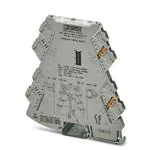
Signal conditioner - MINI MCR-2-UNI-UI-UIRO - 2902026
Please be informed that the data shown in this PDF Document is generated from our Online Catalog. Please find the complete data in the user's
documentation. Our General Terms of Use for Downloads are valid
(http://phoenixcontact.com/download)
Universally configurable 4-way signal conditioner, with switching output and plug-in connection technology for
the electrical isolation of analog signals. Configurable via DIP switch or software. Screw connection technology,
standard configuration.
Product description
Configurable, freely adjustable 4-way signal conditioner with switching output and plug-in connection technology for the electrical isolation, conversion,
amplification, and filtering of standard signals. Current signals between 0 mA ... 24 mA and voltage signals between 0 V ... 12 V can be processed on
the input side. Signals between 0 mA ... 21 mA and 0 V ... 10.5 V are possible on the output side. The minimum measuring span is 1 mA and 0.5 V.
Full accuracy is maintained with a measuring span greater than 10 mA and 5 V. You can configure the device using one of the free software solutions.
Default settings can also be made directly on the device by simply using the DIP switches (see configuration table). The measuring transducer supports
fault monitoring and NFC communication.
Key commercial data
Packing unit
1 pc
Weight per Piece (excluding packing)
40.0 GRM
Custom tariff number
85437090
Country of origin
Germany
Technical data
Note
Utilization restriction
EMC: class A product, see manufacturer's declaration in the download
area
Dimensions
Width
6.2 mm
Height
110.5 mm
Depth
120.5 mm
Ambient conditions
Ambient temperature (operation)
-40 °C ... 70 °C
07/07/2015 Page 1 / 6
�https://www.phoenixcontact.com/us/products/2902026
Signal conditioner - MINI MCR-2-UNI-UI-UIRO - 2902026
Technical data
Ambient conditions
Ambient temperature (storage/transport)
-40 °C ... 85 °C
Degree of protection
IP20
Input data
Number of inputs
1
Configurable/programmable
Yes
Voltage input signal
0 V ... 10 V (via DIP switch)
2 V ... 10 V (via DIP switch)
0 V ... 5 V (via DIP switch)
1 V ... 5 V (via DIP switch)
10 V ... 0 V (via DIP switch)
10 V ... 2 V (via DIP switch)
5 V ... 0 V (via DIP switch)
5 V ... 1 V (via DIP switch)
0 V ... 12 V (Can be set via software)
Current input signal
0 mA ... 20 mA (via DIP switch)
4 mA ... 20 mA (via DIP switch)
0 mA ... 10 mA (via DIP switch)
2 mA ... 10 mA (via DIP switch)
20 mA ... 0 mA (via DIP switch)
20 mA ... 4 mA (via DIP switch)
10 mA ... 0 mA (via DIP switch)
10 mA ... 2 mA (via DIP switch)
0 mA ... 24 mA (Can be set via software)
Max. input voltage
12 V
Max. input current
24 mA
Input resistance of voltage input
> 120 kΩ
Input resistance current input
approx. 50 Ω
Output data
Number of inputs
1
Configurable/programmable
Yes
Voltage output signal
0 V ... 10 V (via DIP switch)
2 V ... 10 V (via DIP switch)
0 V ... 5 V (via DIP switch)
1 V ... 5 V (via DIP switch)
0 V ... 10.5 V (Can be set via software)
Current output signal
0 mA ... 20 mA (via DIP switch)
07/07/2015 Page 2 / 6
�https://www.phoenixcontact.com/us/products/2902026
Signal conditioner - MINI MCR-2-UNI-UI-UIRO - 2902026
Technical data
Output data
4 mA ... 20 mA (via DIP switch)
0 mA ... 10 mA (via DIP switch)
2 mA ... 10 mA (via DIP switch)
0 mA ... 21 mA (Can be set via software)
Max. output voltage
approx. 12.3 V
Max. output current
24.6 mA
Load/output load voltage output
≥ 10 kΩ
Load/output load current output
≤ 600 Ω (at 20 mA)
Switching output
Output name
Switching output
Number of outputs
1
Contact type
1 N/O contact
Maximum switching voltage
30 V DC
Power supply
Nominal supply voltage
24 V DC
Supply voltage range
9.6 V DC ... 30 V DC (The DIN rail bus connector (ME 6,2 TBUS-2 1,5/5ST-3,81 GN, Order No. 2869728) can be used to bridge the supply
voltage. It can be snapped onto a 35 mm DIN rail according to EN 60715))
Typical current consumption
32 mA (24 V DC)
63 mA (12 V DC)
Power consumption
≤ 1 W (at IOUT = 20 mA, 9.6 V DC, 600 Ω load)
Connection data
Connection method
Screw connection
Single conductor/terminal point, solid, with ferrule, min.
0.2 mm²
Single conductor/terminal point, solid, with ferrule, max.
1.5 mm²
Single conductor/terminal point, solid, without ferrule, min.
0.2 mm²
Single conductor/terminal point, solid, without ferrule, max.
2.5 mm²
Conductor cross section flexible min.
0.2 mm²
Conductor cross section flexible max.
1.5 mm²
Min. AWG conductor cross section, flexible
24
Max. AWG conductor cross section, flexible
12
Stripping length
10 mm
Screw thread
M3
General
Maximum transmission error
0.1 % (of final value)
Maximum temperature coefficient
0.01 %/K
07/07/2015 Page 3 / 6
�https://www.phoenixcontact.com/us/products/2902026
Signal conditioner - MINI MCR-2-UNI-UI-UIRO - 2902026
Technical data
General
Step response (10-90%)
approx. 140 ms (15 Hz sample rate)
approx. 45 ms (60 Hz sample rate)
approx. 25 ms (240 Hz sample rate)
Status display
Yellow LED (switching output)
Electrical isolation
Reinforced insulation in accordance with IEC 61010-1
Surge voltage category
II
Pollution degree
2
Rated insulation voltage
300 V
Test voltage, input/output/supply
3 kV (50 Hz, 1 min.)
Electromagnetic compatibility
Conformance with EMC Directive 2004/108/EC
Noise emission
EN 61000-6-4
Noise immunity
EN 61000-6-2 When being exposed to interference, there may be minimal
deviations.
Color
gray
Housing material
PBT
Mounting position
any
Assembly instructions
The T connector can be used to bridge the supply voltage. It can be
snapped onto a 35 mm DIN rail according to EN 60715.
Conformance
CE-compliant
ATEX
II 3 G Ex nA IIC T4 Gc X
UL, USA / Canada
UL 508 Listed
Class I, Div. 2, Groups A, B, C, D T6
Class I, Zone 2, Group IIC T6
GL
GL applied for
EMC data
Designation
Electromagnetic RF field
Standards/regulations
EN 61000-4-3
Typical deviation from the measuring range final value
0.2 %
Designation
Fast transients (burst)
Standards/regulations
EN 61000-4-4
Typical deviation from the measuring range final value
0.1 %
Designation
Conducted interferences
Standards/regulations
EN 61000-4-6
Typical deviation from the measuring range final value
2.8 %
07/07/2015 Page 4 / 6
�https://www.phoenixcontact.com/us/products/2902026
Signal conditioner - MINI MCR-2-UNI-UI-UIRO - 2902026
Classifications
eCl@ss
eCl@ss 4.0
27040702
eCl@ss 4.1
27040702
eCl@ss 5.0
27242213
eCl@ss 5.1
27049002
eCl@ss 6.0
27049002
eCl@ss 7.0
27049002
eCl@ss 8.0
27210121
ETIM
ETIM 3.0
EC001039
ETIM 4.0
EC002540
ETIM 5.0
EC002653
UNSPSC
UNSPSC 6.01
30211502
UNSPSC 7.0901
39121004
UNSPSC 11
39121004
UNSPSC 12.01
39121004
UNSPSC 13.2
39121004
Approvals
Approvals
Approvals
UL Listed / cUL Listed / cULus Listed
Ex Approvals
UL Listed / cUL Listed / ATEX / cULus Listed
Approvals submitted
Approval details
07/07/2015 Page 5 / 6
�https://www.phoenixcontact.com/us/products/2902026
Signal conditioner - MINI MCR-2-UNI-UI-UIRO - 2902026
Approvals
UL Listed
cUL Listed
cULus Listed
Drawings
Block diagram
Sensor / Field
Pictogram
OUT
IN
PLC / DCS
S-Port
TI–
+ 1
OUT
1
U, I+
US
OUT
2
U, I–
TI+
5 +
OUT U, I+
active
IN U, I+
4-wire
– 2
– 4
passive
6 –
OUT U, I–
IN U, I–
+ 3
5
RO+
PWR+
RO–
6
U,I
7 +
PWR–
8 –
FM
IN
U,I
OUT
PWR–
PWR+
FM
POWER
Zone 2
Phoenix Contact 2015 © - all rights reserved
http://www.phoenixcontact.com
07/07/2015 Page 6 / 6
�