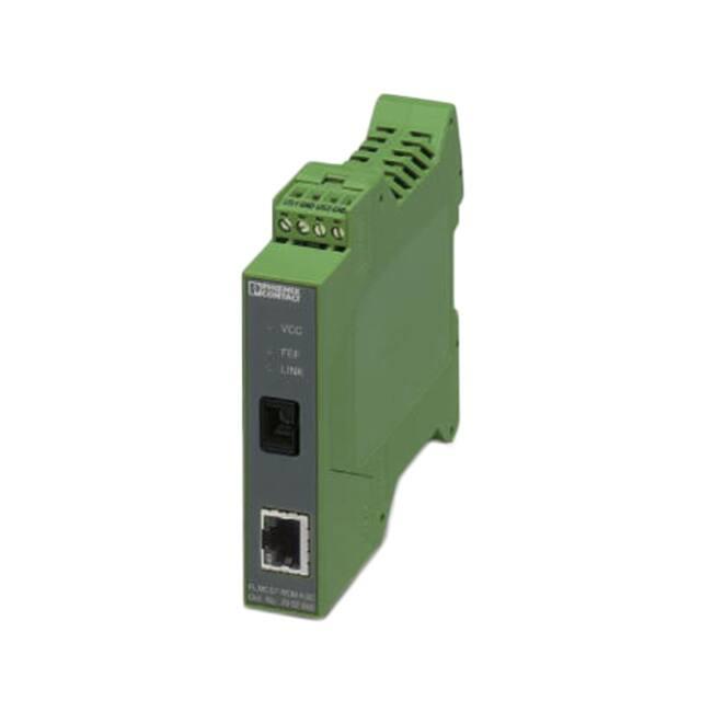
FL MC EF WDM ...
Ethernet FO converter for bidirectional data
transmission via a single optical fiber (SC simplex)
Data sheet
104915_en_04
1
© PHOENIX CONTACT 2017-03-20
Description
The FL MC EF WDM... media converters enable full duplex
communication via a single glass fiber thanks to WDM
(wavelength division multiplex) technology. A 10/100BaseT(X) Ethernet interface is converted into an optical fiber.
Both devices use 1310 nm and 1550 nm wavelengths to
transmit and receive. Devices A and B are used as a set.
Transmission via a single fiber provides many advantages.
You save on optical fibers and plugs. Double the bandwidth
can be achieved with the existing cabling. WDM media
converters are particularly suitable for rotating applications
with optical rotary transformers, such as wind turbine
generators.
Features
–
–
–
–
–
–
–
–
–
–
–
Full duplex transmission via a single optical fiber
10/100Base-T(X) auto negotiation
Auto MDI/MDIx switchover
Operating mode and speed can be set manually
Link fault pass through (LFP)
Far End Fault signaling (FEF)
SC simplex connection
Redundant power supply possible
Extended temperature range of -40°C ... +65°C
Mounting on a 35 mm DIN rail
Shipbuilding approval according to DNV
WARNING: Explosion hazard when used in potentially explosive areas
The device is a category 3 item of electrical equipment. Follow the instructions provided here during
installation and observe the safety notes.
Make sure you always use the latest documentation.
It can be downloaded from the product at phoenixcontact.net/products.
For data transmission, you always require a type A device and a type B device for the remote station!
This document is valid for the products listed in the “Ordering data”.
�FL MC EF WDM ...
2
Table of contents
1
Description .............................................................................................................................. 1
2
Table of contents ..................................................................................................................... 2
3
Ordering data .......................................................................................................................... 3
4
Technical data ......................................................................................................................... 6
5
Safety regulations and installation notes.................................................................................. 9
5.1
Installation notes ................................................................................................................. 9
5.2
Installation in Zone 2............................................................................................................. 9
6
Structure................................................................................................................................ 11
6.1
Dimensions ...................................................................................................................... 11
6.2
Block diagram ................................................................................................................... 11
6.3
Function elements ............................................................................................................. 12
6.4
Diagnostics and status indicators........................................................................................... 12
7
Configuration via DIP switches .............................................................................................. 13
7.1
Setting data transmission (DIP 1, DIP 2, and DIP 3) .................................................................... 13
7.2
Pause frame (DIP 4) ........................................................................................................... 14
7.3
Link fault pass through (DIP 6) .............................................................................................. 14
8
Assembly............................................................................................................................... 15
8.1
Mounting on a DIN rail ........................................................................................................ 15
8.2
Combined assembly ........................................................................................................... 15
8.3
Removal .......................................................................................................................... 15
8.4
Power Supply Voltage ......................................................................................................... 16
9
Twisted pair interface (TP port).............................................................................................. 16
10
Fiber optic interface (FO port)................................................................................................ 17
11
Application examples ............................................................................................................ 17
12
Error localization.................................................................................................................... 18
12.1 Normal operation ............................................................................................................... 18
12.2 Fault on the copper cable .................................................................................................... 18
12.3 Fault on the fiber optic cable ................................................................................................. 18
104915_en_04
PHOENIX CONTACT 2 / 18
�FL MC EF WDM ...
3
Ordering data
Description
Type
Order No.
Pcs./Pkt.
FO converter (replacement device A), for full duplex
FL MC EF WDM-A SC
transmission from 10/100Base-T(X) to individual simplex
fiberglass with WDM (wavelength division multiplex)
technology, SC simplex fiber optic connection
(1310/1550 nm). Device set (type A and type B) required
for operation.
2902658
1
FO converter (replacement device B), for full duplex
FL MC EF WDM-B SC
transmission from 10/100Base-T(X) to individual simplex
fiberglass with WDM (wavelength division multiplex)
technology, SC simplex fiber optic connection
(1550/1310 nm). Device set (type A and type B) required
for operation.
2902659
1
FO converter set, consisting of type A devices and type B FL MC EF WDM-SET SC
devices, for full duplex transmission from 10/100BaseT(X) to individual simplex fiberglass with WDM
(wavelength division multiplex) technology.
SC simplex fiber optic connection (1550/1310 nm).
2902660
1
Accessories
Order No.
Pcs./Pkt.
CAT5-SF/UTP cable (J-02YS(ST)C HP 2 x 2 x 24 AWG), FL CAT5 HEAVY
heavy-duty installation cable, 2 x 2 x 0.22 mm²,
solid conductor, shielded, outer sheath: 7.8 mm diameter,
inner sheath: 5.75 mm ± 0.15 mm diameter
2744814
1
CAT5-SF/UTP cable (J-LI02YS(ST)C H 2 x 2 x 26 AWG), FL CAT5 FLEX
light-duty, flexible installation cable 2 x 2 x 0.14 mm²,
stranded, shielded, outer sheath: 5.75 mm ± 0.15 mm
diameter
2744830
1
Crimping pliers, for assembling the RJ45 plugs
FL PLUG RJ45..., for assembly on site
2744869
1
Plug component, Nominal current: 8 A,
ME 22,5 TBUS 1,5/ 5-ST-3,81
Nominal current (Ex): 8 A, Nominal voltage (Ex): 125 V,
GN
Number of positions: 5, Pitch: 3.81 mm, Articles with goldplated contacts, bus connectors for connecting with
electronic housings
2707437
50
Primary-switched MINI POWER supply for DIN rail
mounting, input: 1-phase, output: 24 V DC/1.5 A
MINI-SYS-PS-100-240AC/
24DC/1.5
2866983
1
DIN rail connector for DIN rail mounting. Universal for
TBUS housing. Gold-plated contacts, 5-pos. Header,
Nominal current: 8 A, Number of positions: 5,
Pitch: 3.81 mm, Articles with gold-plated contacts,
bus connectors for connecting with electronic housings
ME 17,5 TBUS 1,5/ 5-ST-3,81 2709561
GN
Type
FL CRIMPTOOL
Assembled FO cable, break out cable, multimode
FL MM PATCH 1,0 LC-SC
fiberglass 50/125 µm (OM2), connector: LC/SC duplex,
degree of protection: IP20, for installation in cable ducts or
control cabinets, length: 1 m
104915_en_04
2989161
10
1
PHOENIX CONTACT 3 / 18
�FL MC EF WDM ...
Accessories
Order No.
Pcs./Pkt.
Assembled FO cable, break out cable, multimode
FL MM PATCH 2,0 LC-SC
fiberglass 50/125 µm (OM2), connector: LC/SC duplex,
degree of protection: IP20, for installation in cable ducts or
control cabinets, length: 2 m
2989268
1
Assembled FO cable, break out cable, multimode
FL MM PATCH 5,0 LC-SC
fiberglass 50/125 µm (OM2), connector: LC/SC duplex,
degree of protection: IP20, for installation in cable ducts or
control cabinets, length: 5 m
2901800
1
Assembled FO cable, break out cable, multimode
fiberglass 50/125 µm (OM2), connector: SC duplex/
SC duplex, degree of protection: IP20, for installation in
cable ducts or control cabinets, length: 1 m
FL MM PATCH 1,0 SC-SC
2901805
1
Assembled FO cable, break out cable, multimode
fiberglass 50/125 µm (OM2), connector: SC duplex/
SC duplex, degree of protection: IP20, for installation in
cable ducts or control cabinets, length: 2 m
FL MM PATCH 2,0 SC-SC
2901807
1
Assembled FO cable, break out cable, multimode
fiberglass 50/125 µm (OM2), connector: SC duplex/
SC duplex, degree of protection: IP20, for installation in
cable ducts or control cabinets, length: 5 m
FL MM PATCH 5,0 SC-SC
2901808
1
Assembled FO cable, break out cable, multimode
fiberglass 50/125 µm (OM2), connector: SC duplex/
B-FOC (STR), degree of protection: IP20, for installation
in cable ducts or control cabinets, length: 1 m
FL MM PATCH 1,0 SC-ST
2901809
1
Assembled FO cable, break out cable, multimode
fiberglass 50/125 µm (OM2), connector: SC duplex/
B-FOC (STR), degree of protection: IP20, for installation
in cable ducts or control cabinets, length: 2 m
FL MM PATCH 2,0 SC-ST
2901810
1
Assembled FO cable, break out cable, multimode
fiberglass 50/125 µm (OM2), connector: SC duplex/
B-FOC (STR), degree of protection: IP20, for installation
in cable ducts or control cabinets, length: 5 m
FL MM PATCH 5,0 SC-ST
2901811
1
Assembled FO cable, break out cable, multimode
FL MM PATCH 1,0 SC-SCRJ
fiberglass 50/125 µm (OM2), connector: SC duplex/
SC-RJ, degree of protection: IP20, for installation in cable
ducts or control cabinets, length: 1 m
2901812
1
Assembled FO cable, break out cable, multimode
FL MM PATCH 2,0 SC-SCRJ
fiberglass 50/125 µm (OM2), connector: SC duplex/
SC-RJ, degree of protection: IP20, for installation in cable
ducts or control cabinets, length: 2 m
2901813
1
Assembled FO cable, break out cable, multimode
FL MM PATCH 5,0 SC-SCRJ
fiberglass 50/125 µm (OM2), connector: SC duplex/
SC-RJ, degree of protection: IP20, for installation in cable
ducts or control cabinets, length: 5 m
2901814
1
Rugged GOF installation cable (IP20 heads only) for inner FOC-GDM-RUGGED-1016/
areas with highly tear-proof aramid strain-relief elements. IP20/...
Individual elements consist of highly flexible FRNC
material. The cable is halogen-free, ozone and UV
resistant and has a rugged polyurethane (PUR) outer
sheath.
2901558
1
104915_en_04
Type
PHOENIX CONTACT 4 / 18
�FL MC EF WDM ...
Accessories
Type
Order No.
Pcs./Pkt.
Rugged GOF installation cable for inner areas with highly FOC-GDM-RUGGED-1016/... 1402193
tear-proof aramid strain-relief elements. Individual
elements consist of highly flexible FRNC material.
The cable is halogen-free, ozone and UV resistant and
has a rugged polyurethane (PUR) outer sheath.
1
Highly rugged GOF round cable (IP20 heads only) for
assembly and for outdoor installation with integrated
moisture barrier as well as rodent-proof scrim. Individual
elements made from highly flexible FRNC material.
The wire is ozone and UV resistant with a very rugged
polyethylene outer sheath.
2901559
1
Highly rugged GOF round cable for assembly and for
FOC-GDO-1017/...
outdoor installation with integrated moisture barrier as well
as rodent-proof scrim. Individual elements made from
highly flexible FRNC material. The wire is ozone and
UV resistant with a very rugged polyethylene outer sheath.
1402194
1
Fiberglass cable, duplex 50/125 µm, by the meter,
without connector, for outdoor installation
PSM-LWL-GDO- 50/125
2799432
1
Fiberglass cable, duplex 50/125 µm, by the meter,
without connector, for indoor installation
PSM-LWL-GDM-RUGGED50/125
2799322
1
Assembled fiber optic cable, break-out cable, fiberglass FL SM PATCH 1,0 LC-SC
single mode 9/125 µm (OS2, Low Water Peak Fiber)
connector: LC/SC duplex, degree of protection: IP20, for
installation in cable ducts or control cabinets, length: 1 m
2989190
1
Assembled fiber optic cable, break-out cable, fiberglass FL SM PATCH 2,0 LC-SC
single mode 9/125 µm (OS2, Low Water Peak Fiber)
connector: LC/SC duplex, degree of protection: IP20, for
installation in cable ducts or control cabinets, length: 2 m
2989297
1
Assembled fiber optic cable, break-out cable, fiberglass FL SM PATCH 5,0 LC-SC
single mode 9/125 µm (OS2, Low Water Peak Fiber)
connector: LC/SC duplex, degree of protection: IP20, for
installation in cable ducts or control cabinets, length: 5 m
2901827
1
Assembled fiber optic cable, break-out cable, fiberglass
single mode 9/125 µm (OS2, Low Water Peak Fiber)
connector: SC duplex/SC duplex, degree of protection:
IP20, for installation in cable ducts or control cabinets,
length: 1 m
FL SM PATCH 1,0 SC-SC
2901829
1
Assembled fiber optic cable, break-out cable, fiberglass
single mode 9/125 µm (OS2, Low Water Peak Fiber)
connector: SC duplex/SC duplex, degree of protection:
IP20, for installation in cable ducts or control cabinets,
length: 2 m
FL SM PATCH 2,0 SC-SC
2901830
1
Assembled fiber optic cable, break-out cable, fiberglass
single mode 9/125 µm (OS2, Low Water Peak Fiber)
connector: SC duplex/SC duplex, degree of protection:
IP20, for installation in cable ducts or control cabinets,
length: 5 m
FL SM PATCH 5,0 SC-SC
2901831
1
104915_en_04
FOC-GDO-1017/IP20/...
PHOENIX CONTACT 5 / 18
�FL MC EF WDM ...
Accessories
Type
Order No.
Pcs./Pkt.
Assembled fiber optic cable, break-out cable, fiberglass FL SM PATCH 1,0 SC-ST
single mode 9/125 µm (OS2, Low Water Peak Fiber)
connector: SC duplex/B-FOC (STR),
degree of protection: IP20, for installation in cable ducts or
control cabinets, length: 1 m
2901832
1
Assembled fiber optic cable, break-out cable, fiberglass FL SM PATCH 2,0 SC-ST
single mode 9/125 µm (OS2, Low Water Peak Fiber)
connector: SC duplex/B-FOC (STR),
degree of protection: IP20, for installation in cable ducts or
control cabinets, length: 2 m
2901833
1
Assembled fiber optic cable, break-out cable, fiberglass FL SM PATCH 5,0 SC-ST
single mode 9/125 µm (OS2, Low Water Peak Fiber)
connector: SC duplex/B-FOC (STR),
degree of protection: IP20, for installation in cable ducts or
control cabinets, length: 5 m
2901834
1
RJ45 connector, Degree of protection: IP20,
VS-08-RJ45-5-Q/IP20
Number of positions: 8, 1 Gbps, CAT5 (IEC 11801:2002),
Material: PA, Connection method: IDC fast connection,
Connection cross section: AWG 26-23,
Cable exit: straight
1656725
1
Patch cable, CAT5, assembled, 0.5 m
FL CAT5 PATCH 0,5
2832263
10
Patch cable, CAT5, assembled, 1 m
FL CAT5 PATCH 1,0
2832276
10
Patch cable, CAT5, assembled, 2 m
FL CAT5 PATCH 2,0
2832289
10
Patch cable, CAT5, assembled, 3 m
FL CAT5 PATCH 3,0
2832292
10
4
Technical data
Supply
Supply voltage range
18 V DC ... 30 V DC (Screw connection)
18 V DC ... 30 V DC (as an alternative or redundant, via
backplane bus contact and system current supply)
Typical current consumption
< 110 mA (24 V DC)
Protective circuit
Reverse polarity protection
Electrical isolation
VCC // FE // Ethernet
Test voltage data interface/power supply
1.5 kVrms (50 Hz, 1 min.)
Torque
0.56 Nm ... 0.79 Nm
Ethernet interface, 10/100Base-T(X) in acc. with IEEE 802.3u
Connection method
RJ45 socket, shielded
Transmission speed
10/100 Mbps
Transmission length
100 m (shielded twisted pair)
Transmission medium
Copper
Auto-negotiation modes
Auto
Link through
Link fault pass through
MDI-/MDI-X switchover
Auto-MDI(X)
Signal LEDs
Activity, link status, 10/100 Mbps
104915_en_04
PHOENIX CONTACT 6 / 18
�FL MC EF WDM ...
FO interface
Data rate
100 Mbps
Connection method
SC simplex
Wavelength
1310 nm
1550 nm
Laser protection
Class 1 according to DIN EN 60825-1
Transmission length incl. 3 dB system reserve
38 km (with F-E 9/125 0.36 dB/km)
34 km (with F-E 9/125 0.4 dB/km)
28 km (with F-E 9/125 0.5 dB/km)
21 km (with F-G 62,5/125 0,7 dB/km F 1000)
5.5 km (with F-G 62.5/125 2.6 dB/km F 600)
21 km (with F-G 50/125 0,7 dB/km F 1200)
9 km (with F-G 50/125 1,6 dB/km F 800)
Transmit capacity, minimum
≥ -14 dBm ((9/125 µm) dynamic in link mode (average))
Transmit capacity, maximum
≤ -8 dBm ((9/125 µm) dynamic in link mode (average))
Minimum receiver sensitivity
-31 dBm (dynamic in link mode (average))
Overrange receiver
-3 dBm (dynamic in link mode (average))
Signal LEDs
Far end fault (red LED), link status (yellow LED)
General data
Basic functions
Store-and-forward media converter
Degree of protection
IP20
Dimensions (W/H/D)
22.5 mm x 99 mm x 114.5 mm
Housing material
PA 6.6-FR green
Free fall in acc. with IEC 60068-2-32
1m
Vibration resistance in acc. with EN 60068-2-6/
IEC 60068-2-6
5g, 10...150 Hz, 2.5 h, in XYZ direction
Shock in acc. with EN 60068-2-27/IEC 60068-2-27
25g, 11 ms period, half-sine shock pulse
MTTF (mean time to failure) SN 29500 standard,
temperature 25 °C, operating cycle 21 %
(5 days a week, 8 hours a day)
1400 Years
MTTF (mean time to failure) SN 29500 standard,
temperature 40 °C, operating cycle 34.25 %
(5 days a week, 12 hours a day)
599 Years
MTTF (mean time to failure) SN 29500 standard,
temperature 40 °C, operating cycle 100 %
(7 days a week, 24 hours a day)
101 Years
Electromagnetic compatibility
Conformance with EMC Directive 2014/30/EU
Ambient conditions
Ambient temperature (operation)
-40 °C ... 65 °C
Ambient temperature (storage/transport)
-40 °C ... 85 °C
Permissible humidity (operation)
30 % ... 95 % (non-condensing)
Permissible humidity (storage/transport)
30 % ... 95 % (non-condensing)
Altitude
5000 m (For restrictions see manufacturer's declaration)
2000 m (With UL approval)
104915_en_04
PHOENIX CONTACT 7 / 18
�FL MC EF WDM ...
Approvals / Certificates
Conformance
CE-compliant
Free from substances that could impair the application of according to P-VW 3.10.7 57 65 0 VW-AUDI-Seat central
coating
standard
ATEX
Please follow the special installation instructions in the
documentation!
II 3 G Ex nA IIC T4 Gc X
UL, USA/Canada
cULus listed UL 508
Class I, Zone 2, AEx nA IIC T4
Class I, Zone 2, Ex nA IIC T4 Gc X
Class I, Div. 2, Groups A, B, C, D
Standards/regulations
EN 60950-1
Shipbuilding approval
DNV
Conformance with EMC Directive 2014/30/EU
Noise immunity according to EN 61000-6-2
Electrostatic discharge
EN 61000-4-2
Contact
discharge
± 6 kV (Test Level 3)
Discharge in air
± 8 kV (Test Level 3)
Indirect discharge ± 6 kV
Comments
Electromagnetic HF field
Fast transients (burst)
Surge current loads (surge)
Conducted interference
Criterion B
EN 61000-4-3
Frequency range
80 MHz ... 3 GHz (Test Level 3)
Field intensity
10 V/m
Comments
Criterion A
EN 61000-4-4
Input
± 2 kV (Test Level 3)
Signal
± 2 kV (Test Level 3)
Comments
Criterion B
EN 61000-4-5
Input
± 0.5 kV (DC supply)
Signal
± 1 kV (Data line, asymmetrical)
Comments
Criterion B
EN 61000-4-6
Frequency range
0.15 MHz ... 80 MHz
Voltage
10 V
Comments
Criterion A
Emitted interference in acc. with EN 61000-6-4
Interference emission
Criterion A
Criterion B
104915_en_04
EN 55032, Class A, industrial applications
Normal operating behavior within the specified limits
Temporary impairment of operating behavior that is corrected by the device itself
PHOENIX CONTACT 8 / 18
�FL MC EF WDM ...
5
Safety regulations and installation notes
5.1
Installation notes
5.2
WARNING: Explosion hazard when used
in potentially explosive areas
CAUTION:
Observe the following safety notes when
using the device.
•
•
•
•
•
•
•
The category 3 device is designed for installation in
zone 2 potentially explosive areas. It meets the
requirements of EN 60079-0:2012+A11:2013 and
EN 60079-15:2010.
Installation, operation, and maintenance may only be
carried out by qualified electricians. Follow the
installation instructions as described.
When installing and operating the device, the
applicable regulations and safety directives (including
national safety directives), as well as general technical
regulations, must be observed. The technical data is
provided in the package slip and on the certificates
(conformity assessment, additional approvals where
applicable).
The device must not be opened or modified apart from
the configuration of the DIP switches. Do not repair the
device yourself but replace it with an equivalent device.
Repairs may only be carried out by the manufacturer.
The manufacturer is not liable for damage resulting from
a failure to comply.
The IP20 protection (IEC 60529/EN 60529) of the
device is intended for use in a clean and dry
environment. The device must not be subject to
mechanical strain and/or thermal loads, which exceed
the limits described.
The device is not designed for use in atmospheres with
a danger of dust explosions.
If dust is present, it is necessary to install into a suitable
approved housing, whereby the surface temperature of
the housing must be taken into consideration.
104915_en_04
Installation in Zone 2
Please make sure that the following notes and
instructions are observed.
•
•
•
•
•
•
•
Observe the specified conditions for use in potentially
explosive areas.
The device should be installed so that a degree of
protection of at least IP54 is achieved in accordance
with EN 60529. To this end, a suitable, approved
housing that meets the requirements of EN 60079-15
should be used.
Only devices that are designed for operation in
Ex Zone 2 and the conditions at the installation location
may be connected to the circuits in Zone 2.
In potentially explosive areas, terminals may only be
snapped onto or off the DIN rail connector and wires
may only be connected or disconnected when the
power is switched off.
The switches of the device that can be accessed may
only be actuated when the power supply to the device is
disconnected.
The device must be stopped and immediately removed
from the Ex area if it is damaged, was subject to an
impermissible load, stored incorrectly or if it
malfunctions.
For reliable operation, the RJ45 plug needs to have a
fully functioning locking clip. Repair any damaged plugs
immediately.
PHOENIX CONTACT 9 / 18
�FL MC EF WDM ...
UL note
INDUSTRIAL CONTROL EQUIPMENT 11AE
Wire Range: 24-14 AWG
Torque: 5-7 (Lbs-Ins)
Environmental designation: "Open Type Device"
"Pollution Degree 2 Installation Environment"
PROCESS CONTROL EQUIPMENT FOR HAZARDOUS LOCATIONS 31ZN
A) This equipment is suitable for use in Class I, Zone 2, AEx nA IIC T4; Ex nA IIC T4 Gc X
or Class I, Division 2, Groups A, B, C, D or non-hazardous locations only.
B) Provision shall be made to prevent transient disturbances of more than 140% of the
rated supply voltage.
C) The device must be installed in a Class I, Zone 2 certified overall enclosure rated IP54
with tool-accessible only cover or door and in degree of pollution 2 environment only.
D) Unit shall be supplied by Limited Energy circuit according to clause 9.4 of UL 61010-1
3rd edition of Limited Power Source according to clause 2.5 of UL 60950-1 or NEC Class 2.
E) Conductor temperature rating must be 72°C or higher.
F) Maximum relative humidity 80 % for temperatures up to 31°C decreasing linearly to 50 %
relative humidity at 40°C.
104915_en_04
PHOENIX CONTACT 10 / 18
�FL MC EF WDM ...
6
Structure
6.1
Dimensions
114,5
22,5
VCC
FEF
99
LINK
FL MC EF WDM-A SC
Ord.-No.: 29 02 658
Figure 1
6.2
Housing dimensions
Block diagram
Figure 2
104915_en_04
Block diagram
PHOENIX CONTACT 11 / 18
�FL MC EF WDM ...
6.3
Function elements
10
1
6.4
2
ON
6
U
S
1
G
N
D
U
S
2
G
N
D
1
C
VC
F
FE
K
LIN
9
8
Figure 3
1
2
3
4
5
6
7
8
9
10
11
7
ST
MM
00 54
13 0 28
EF . 29
M C No
FL rd.O
6
3
4
5
Function elements
24 V DC Supply voltage
24 V DC Supply voltage, redundant
Fiber optic (FO-) interface, SC simplex
RJ45 Ethernet port, 10/100 Base-T(X)
LED
Link/Activity/10/100
LED
HD/FD
LED
LINK
LED
FEF
LED
VCC
Functional earth ground
DIP switch
104915_en_04
11
Diagnostics and status indicators
Ethernet interface (TP port)
5 Link/Activity/10/100
Yellow ON
10 Mbps link
Flashing 10 Mbps link - active data
transmission
Green ON
100 Mbps link
Flashing 100 Mbps link - active
data transmission
6 HD/FD Green OFF
Half duplex transmission
ON
Full duplex transmission
Fiber optics interface (FO port)
7 LINK
Yellow ON
Fiber optics link
available, no data
communication
Flashing Data transmission at FO
port
8 FEF
Red
ON
Far end fault has
occurred. Remote station
reports: "no light".
Supply voltage
9 VCC
Green
ON
Supply voltage OK
Far End Fault signal (FEF)
If the copper connection is interrupted at one of the FO
converters, data communication for both FO converters in
both the optical and copper segment is disabled by the link
fault pass through function. In this case, all Link LEDs go out.
However, in order that error diagnostics can be carried out,
the red FEF LED lights up on the FO converter where the
copper segment is interrupted.
PHOENIX CONTACT 12 / 18
�FL MC EF WDM ...
7
Configuration via DIP switches
NOTE: electrostatic discharge!
The device contains components that can be
damaged or destroyed by electrostatic
discharge. When handling the device,
observe the necessary safety precautions
against electrostatic discharge (ESD)
according to EN 61340-5-1 and
IEC 61340-5-1.
FL MC EF 1300
LED
DIP
6
5
4
3
2
1
ON
permanent
GN - VCC
RD - FEF
YE - LINK
GN - RJ45
GN/YE - RJ45
flashing
Device ON
Far End Fault
Activity FO
Link FO
Full Duplex
100/10 MBit/s Activity CU
ON
OFF (DEFAULT)
Local Link
not used
Pass Pause Frame
Half Duplex
10 MBit/s
Fixed Data Rate
Link Pass Through
not used
Drop Pause Frame
Full Duplex
100 MBit/s
Autonegotiation
6
1
Only select the mode of operation when the
power is disconnected! The change is
activated after renewed power up.
A
U
S
1
G
N
D
U
S
2
G
N
D
Figure 5
C
VC
F
FE
K
IN
L
B
DIP
6
5
4
3
2
1
DIP switches
ON
LFP deactivated (local)
Not used
Pass pause frame
Half duplex transmission
10 Mbps
Fixed transmission
speed on the copper side
OFF (default setting)
LFP activated (global)
Drop pause frame
Full duplex transmission
100 Mbps
Auto negotiation
ST
MM
00 54
13 0 28
EF . 29
MC No
FL rd.O
A
Figure 4
•
•
Opening the housing
Disengage the housing cover with a screwdriver (A).
Then carefully pull the PCB out of the housing as far as
possible (B).
By default, all DIP switches are in the “OFF” position. The
copper side of the device operates in “Auto negotiation”
mode.
7.1
Setting data transmission (DIP 1, DIP 2, and
DIP 3)
DIP 1 = OFF: the connected end devices negotiate
10/100 Mbps transmission speed and half/full transmission
mode directly. The entire path behaves like a directly
connected copper cable.
DIP 1 = ON: you set the transmission speed and mode
manually with DIP switches 2 and 3.
DIP 1
DIP 1
OFF
ON
Auto negotiation
DIP 2 OFF 100 Mbps
ON 10 Mbps
DIP 3 OFF Full duplex transmission
ON Half duplex transmission
If DIP switch 1 is in the “OFF” position, the
position of DIP switch 2 and 3 is not queried.
104915_en_04
PHOENIX CONTACT 13 / 18
�FL MC EF WDM ...
7.2
Pause frame (DIP 4)
A pause frame signal can request an Ethernet device to
temporarily interrupt data transmission. This avoids
overloading the partner when, for example, communication
takes place with different transmission speeds.
DIP 4 = OFF: the device does not respond to an incoming
pause frame signal. It is also not forwarded. A pause frame
signal cannot be generated by the device itself.
The transmission of pause frame signals is negotiated in
sections.
DIP 4 = ON: the device responds to pause frame signals or
forwards them. A pause frame signal can be generated by
the device itself.
7.3
Link fault pass through (DIP 6)
The LFP (link fault pass through) function provides
permanent connection monitoring. The link on the fiber optic
connection switches off if the connection is lost on the
copper side of a FO converter. The FO converter on the
other side registers the aborted link via the fiber optic path
and likewise interrupts the connection for its twisted pair
segment.
The entire connection over the optical path is therefore as
transparent as it would be were communication purely
copper-based. Both sides of the network connection can
therefore detect a lost link immediately and respond
accordingly. In the event of an error, this keeps the network
load low and ensures that redundancy mechanisms can be
activated.
DIP 6 = OFF: the LFP function is activated.
In the event of a fault, the entire connection is disabled
(global).
DIP 6 = ON: the LFP function is deactivated.
In the event of a fault, only the interrupted segment is
disabled (local). This is useful during startup and in the event
of an error.
104915_en_04
PHOENIX CONTACT 14 / 18
�FL MC EF WDM ...
8
8.2
Assembly
Combined assembly
A connection station must not consist of more
than ten devices.
CAUTION: Electric shock
The device is only intended for operation with
SELV according to IEC 60950/EN 60950/
VDE 0805.
Observe the snap-in direction of the device
and DIN rail connector: snap-on foot below
and plug on the left.
NOTE: device damage
Only mount and remove devices when the
power supply is disconnected.
A
C
NOTE: Malfunction
Use a grounding terminal block to connect the
DIN rail to protective earth ground. The
devices are grounded when they are snapped
onto the DIN rail (installation according to
PELV).
This ensures that the shielding is effective.
Connect protective earth ground with low
impedance.
8.1
B
Mounting on a DIN rail
Figure 7
A
B
The DIN rail connector is used to bridge the power supply
and communication.
•
Connect the DIN rail connectors (Order No. 2707437,
1 pc. per device) together for a connection station.
•
Push the connected DIN rail connectors into the DIN
rail.
•
Place the device onto the DIN rail from above. Push the
module from the front toward the mounting surface until
it audibly engages.
8.3
•
Figure 6
Mounting on a DIN rail
•
•
•
•
•
To avoid contact resistance, only use clean, corrosionfree 35 mm DIN rails according to DIN EN 60715.
Install an end bracket next to the left-hand device to
prevent the devices from slipping.
Place the device onto the DIN rail from above. Push the
module from the front toward the mounting surface until
it audibly engages.
Snap the other devices that are to be contacted onto the
DIN rail next to one another.
104915_en_04
Combined assembly
•
Removal
Push down the locking tab with a screwdriver, needlenose pliers or similar.
Slightly pull the bottom edge of the device away from
the mounting surface.
Pull the device away from the DIN rail.
PHOENIX CONTACT 15 / 18
�FL MC EF WDM ...
8.4
Power Supply Voltage
9
Twisted pair interface (TP port)
The device is operated using a 24 V DC SELV.
1 2 3 4
NOTE: Interference
Only use shielded twisted pair cables and
corresponding shielded RJ45 connectors.
11
10
9
FEF
1
2
3
4
24 V DC
0 V DC
24 V DC
0 V DC
Only twisted pair cables with an impedance of 100 Ω
can be connected to the RJ45 Ethernet interface.
LINK
The data transmission speed is 10/100 Mbps
1
8
7
•
VCC
2
5
n.c.
8
n.c.
7
TD-
6
n.c.
5
n.c.
4
TD+
3
RD-
2
RD+
1
6
FL MC EF WDM-A SC
Ord.-No.: 29 02 658
Supply voltage
Supply voltage
Supply voltage, redundant
Supply voltage, redundant
Figure 8
Operation as a single device
•
•
Supply voltage to the device via terminal blocks 1 (24 V)
and 2 (0 V).
Optional: for a redundant power supply, connect an
additional power supply unit to terminal blocks 3 and 4.
•
RJ45
Pin assignment
Insert the Ethernet cable with the RJ45 plug into the
TP interface until the plug engages audibly. Observe
the plug keying.
Combined operation with a system power supply
•
•
Connect a system power supply to two DIN rail
connectors on the left of the group.
– MINI-SYS-PS-100-240AC/24DC/1.5, Order No.
2866983 or
– MINI-PS100-240AC/24DC/1.5/EX, Order No.:
2866653
– Two DIN rail connectors, Order No. 2709561
A second power supply unit can be used to create a
redundant supply concept.
104915_en_04
PHOENIX CONTACT 16 / 18
�FL MC EF WDM ...
10
Fiber optic interface (FO port)
11
Application examples
WARNING: Risk of eye injury
During operation, do not look directly into
transmitter diodes or use visual aids to look
into the glass fibers. The infrared light is not
visible.
Avoid contamination.
Remove the dust protection caps just before
the connectors are connected!
VCC
VCC
FEF
FEF
LINK
LINK
TX (1310nm)
RX (1310nm)
RX (1550nm)
TX (1550nm)
1
1
2
2
FL MC EF WDM-SET SC
Ord.-No.: 29 02 660
FL MC EF WDM-SET SC
Ord.-No.: 29 02 660
Figure 10
When using fiber optics, observe the fiber
optic installation guidelines,
DB GB IBS SYS FOC ASSEMBLY, Order
No. 9423439.
Slip ring communication
For fiber optic transmission, an optical rotary transformer
with a single fiber is used. The rotary transformer is
integrated in the axis of the existing copper slip ring.
U
S
1
G
N
D
U
S
2
G
N
D
Special application: redundant data communication in
wind turbine generators
1
VCC
VCC
FEF
FEF
LINK
1FO
LINK
1
C
VC
F
FE
K
LIN
1
2
2
FL MC EF WDM-SET SC
Ord.-No.: 29 02 660
FL MC EF WDM-SET SC
Ord.-No.: 29 02 660
MODE
MODE
FL SWITCH SMSC 8TX
Ord. No. 2989226
FL SWITCH SMSC 8TX
Ord. No. 2989226
ACT SPD FD
1
3
5
7
2
4
6
8
LINK
3
4
5
6
7
MAC
Address
8
SHDSL
X12
V.24
TC EXTENDER 2001 ETH-2S
SHDSL
•
Remove the dust protection cap.
Insert the fiber optics cable into the SC simplex
connector of the transmit and receive channel. Make
sure that the coding is in the correct position.
Ensure the connector is secure by gently pulling it.
Figure 11
2
3
4
7
6
5
6
8
7
8
X12
V.24
LINK
STAT
LINK
STAT
DIAG
ACT
LINK
ERR
LINK
STAT
LINK
STAT
ETH
ETH
•
•
Connect SC simplex plug
X11
MEM
TC EXTENDER 2001 ETH-2S
USB
DIAG
ACT
LINK
ERR
LAN
ST
MM
00 54
13 028
EF . 29
MC No
FL rd.O
1
Mode
X10
R1 R2
US
DSL B DSL A
US
Figure 9
5
4
US1 US2 FAIL
00.A0.45.06.04.02
X9
US1 GND US2 GND
LAN
2
X11
MEM
DSL B DSL A
1
Mode
X10
R1 R2
2
LINK
US1 US2 FAIL
00.A0.45.06.04.02
X9
US1 GND US2 GND
USB
MAC
Address
3
1
ACT SPD FD
Redundant slip ring communication
In this example, a redundant network ensures data
communication between the hub and the nacelle.
Independent transmission paths are used for data
communication.
With the use of fiber optic technology, standard Ethernet
data transmission is based on two WDM media converters.
The redundant path is constructed with the aid of Ethernet
extenders. The available copper slip ring is used for the
SHDSL connection.
The redundancy management is guaranteed by means of
managed switches. Phoenix Contact provides various
RSTP-capable switches, e.g., FL SWITCH LM 8TX,
2832632 or FL SWITCH SMCS 8TX, 2989226.
104915_en_04
PHOENIX CONTACT 17 / 18
�FL MC EF WDM ...
12
Error localization
12.1
Normal operation
LFP deactivated, local (DIP 6 = ON)
C
VC
F
FE
K
LIN
FL
SC
MM
1300 853
EF 2902
MC -No.
Ord.
FL
GN
D
US
2
GN
D
LAN
US
1
GN
D
US
2
SC
MM
1300 853
EF 2902
MC -No.
Ord.
FL
C
VC
F
FE
K
LIN
TD
SC
MM
1300 853
EF 2902
MC -No.
Ord.
FL
SC
MM
1300 853
EF 2902
MC -No.
Ord.
VCC
VCC
VCC
VCC
FEF
FEF
FEF
FEF
LINK
LINK
LINK
LINK
Diagnostics indicators in normal operation
Fault on the copper cable
The diagnostics indicator depends on DIP 6.
LFP activated, global (DIP 6 = OFF, default setting)
WDM B
US
2
GN
D
LAN
GN
D
C
VC
F
FE
K
LIN
DIP 6 = ON: in the “LFP deactivated, local” setting, only the
Link LEDs of the corresponding port go out in the event of a
fault in a twisted pair segment. The Link LEDs at the copper
port on the other media converter and for the fiber optic
connection are on. The “LFP deactivated, local” setting
therefore enables more precise diagnostics.
12.3
Fault on the fiber optic cable
C
VC
F
FE
K
LIN
TD
VCC
VCC
FEF
FEF
LINK
LINK
C
VC
F
FE
K
LIN
TD
FL
SC
MM
1300 853
EF 2902
MC -No.
Ord.
X
LAN
GN
D
LAN
WDM B
FO
US
2
WDM A
SC
MM
1300 853
EF 2902
MC -No.
Ord.
GN
D
FL
US
1
SC
MM
1300 853
EF 2902
MC -No.
Ord.
LAN fault with LFP deactivated, local
GN
D
TD
FL
Figure 14
US
2
GN
D
US
1
X
US
1
GN
D
FO
US
2
WDM A
LAN
Figure 13
FO
C
VC
F
FE
K
LIN
TD
GN
D
12.2
TD
US
1
Figure 12
X
C
VC
F
FE
K
LIN
TD
WDM B
GN
D
GN
D
US
2
GN
D
LAN
US
1
GN
D
US
2
GN
D
FO
US
1
LAN
WDM A
LAN
WDM B
US
1
WDM A
C
VC
F
FE
K
LIN
TD
FL
SC
MM
1300 853
EF 2902
MC -No.
Ord.
VCC
VCC
FEF
FEF
LINK
LINK
LAN fault with LFP activated, global
DIP 6 = OFF: by default, all Link LEDs go out in the event of
a fault in a twisted pair segment.
The red FEF LED indicates the FO converter where the
twisted pair segment failed.
Figure 15
Fiber optic fault
In the case of FL MC EF WDM... FO converters, only one
glass fiber is used to transmit and receive. Therefore, in the
event that the fiber optic connection is lost, it may not be
easy to detect which FO converter was the first to stop
receiving data.
In this case, the FEF LED cannot be used to determine
whether and at which FO converter the fiber optic
connection is interrupted.
104915_en_04
PHOENIX CONTACT GmbH & Co. KG • 32823 Blomberg • Germany
phoenixcontact.com
18 / 18
�