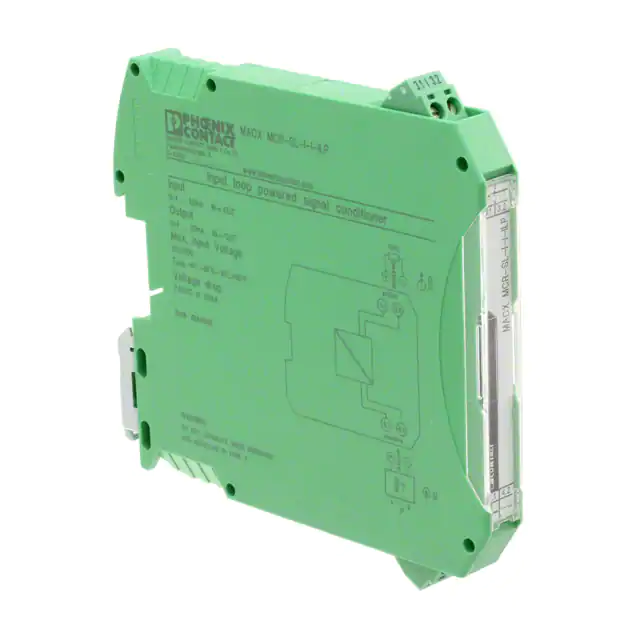
0
登录后你可以
  • 下载海量资料
  • 学习在线课程
  • 观看技术视频
  • 写文章/发帖/加入社区
创作中心
发布
  • 发文章

  • 发资料

  • 发帖

  • 提问

  • 发视频

创作活动
2907704

2907704

  • 厂商:

    PHOENIX(菲尼克斯)

  • 封装:

    -

  • 描述:

    SINGLE-CHANNEL2-WAYISOLATOR

  • 数据手册
  • 价格&库存
2907704 数据手册
MACX MCR-SL-(2)I-(2)I-HV-ILP (-SP) Passive isolator, one and two channel Data sheet 106894_en_01 1 © PHOENIX CONTACT 2015-12-07 Description The single- or dual-channel input loop powered 2-way isolator with increased isolation voltage and plug-in connection technology is used for the electrical isolation and filtering of analog signals. The device allows operation on active sensor technology with a supply voltage of 6 V ... 30 V DC. The device is powered via the current loop of the sensor. Therefore, no additional power supply is necessary. Input signal = output signal: 0(4) mA ... 20 mA Features – – – – – – The measurement signal is transferred 1:1. – – 2-wire passive isolators for electrical isolation and filtering of standard analog signals. Supplied by an input loop 2.9 V voltage drop Up to SIL 3 according to IEC/EN 61508 2-way electrical isolation Plug-in connection terminal blocks, either screw or spring-cage connection technology (Push-in technology) Installation in Ex zone 2 permitted Housing width of 12.5 mm Make sure you always use the latest documentation. It can be downloaded from the product at phoenixcontact.net/products. This document is valid for the products listed in the “Ordering data”. MACX MCR-SL-(2)I-(2)I-HV-ILP(-SP) 2 Table of contents 1 Description .............................................................................................................................. 1 2 Table of contents ..................................................................................................................... 2 3 Ordering data .......................................................................................................................... 3 4 Technical data ......................................................................................................................... 3 5 Safety notes............................................................................................................................. 5 5.1 Installation notes ................................................................................................................. 5 5.2 Installation in the Ex area (zone 2)............................................................................................ 5 5.3 UL Notes ........................................................................................................................... 5 6 Installation ............................................................................................................................... 6 6.1 Connection notes ................................................................................................................ 6 6.2 Electrostatic discharge .......................................................................................................... 6 6.3 Structure ........................................................................................................................... 6 6.4 Basic circuit diagram with connection terminal blocks ................................................................... 7 6.5 Power supply ...................................................................................................................... 7 6.6 Dimensions ........................................................................................................................ 7 6.7 Assembly........................................................................................................................... 8 6.8 Connecting the cables .......................................................................................................... 8 6.9 Startup .............................................................................................................................. 8 7 Method of operation................................................................................................................. 9 8 Safety-related applications ...................................................................................................... 9 8.1 Safety function .................................................................................................................... 9 8.2 Operating mode .................................................................................................................. 9 8.3 Relevant standards .............................................................................................................. 9 8.4 Safety integrity requirements ................................................................................................ 10 8.5 Conditions ....................................................................................................................... 10 8.6 Installation and startup ........................................................................................................ 10 8.7 Notes on operation ............................................................................................................. 11 8.8 Recurring checks ............................................................................................................... 11 8.9 Repair ............................................................................................................................. 11 8.10 Standards ........................................................................................................................ 12 8.11 Abbreviations ................................................................................................................... 12 106894_en_01 PHOENIX CONTACT 2 MACX MCR-SL-(2)I-(2)I-HV-ILP(-SP) 3 Ordering data Description Order No. Pcs./Pkt. Single-channel input loop-powered 2-way isolator with increased cut-off MACX MCR-SL-I-I-HV-ILP voltage and plug-in connection technology for the electrical isolation of analog signals. Input signal = output signal: 0(4) mA ... 20 mA. Screw connection technology. 2907704 1 Single-channel input loop-powered 2-way isolator with increased cut-off MACX MCR-SL-I-I-HV-ILP-SP voltage and plug-in connection technology for the electrical isolation of analog signals. Input signal = output signal: 0(4) mA ... 20 mA. Push-in connection technology. 2907705 1 Two-channel input loop-powered 2-way isolator with increased cut-off volt- MACX MCR-SL-2I-2I-HV-ILP age and plug-in connection technology for the electrical isolation of analog signals. Input signal = output signal: 0(4) mA ... 20 mA. Screw connection technology 2907706 1 Two-channel input loop-powered 2-way isolator with increased cut-off volt- MACX MCR-SL-2I-2I-HV-ILP-SP age and plug-in connection technology for the electrical isolation of analog signals. Input signal = output signal: 0(4) mA ... 20 mA. Push-in connection technology. 2907707 1 4 Type Technical data Input data Description of the input Current input Configurable/programmable no Max. voltage input signal < 30.5 V Current input signal 0 mA ... 20 mA 4 mA ... 20 mA Input voltage limitation 30.5 V Voltage dissipation 2.9 V (I = 20 mA) Step response (10-90%) 5 ms (500 Ω load) Output Output description Current output Configurable/programmable no Output signal maximum voltage 27.5 V Current output signal 0 mA ... 20 mA 4 mA ... 20 mA Transmission Behavior 1:1 to input signal Load/output load current output ≤ 1375 Ω (I = 20 mA) Residual ripple < 10 mVrms (500 Ω load) Supply Supply voltage range 106894_en_01 no separate supply voltage necessary PHOENIX CONTACT 3 MACX MCR-SL-(2)I-(2)I-HV-ILP(-SP) General data Maximum transmission error ≤ 0.1 % (of final value) Maximum temperature coefficient ≤ 0.002 %/K (of measured value / 100 Ω load) Degree of protection IP20 Flammability rating according to UL 94 V0 Overvoltage category II Pollution degree 2 Dimensions W/H/D 12.5 mm / 99 mm / 114.5 mm ( MACX MCR-SL-I-I-HV-ILP ) 12.5 mm / 99 mm / 114.5 mm ( MACX MCR-SL-I-I-HV-ILP-SP ) Type of housing PA 66 green Connection data Screw connection Conductor cross section, solid 0.2 mm² ... 2.5 mm² 0.2 mm² ... 1.5 mm² Conductor cross section, flexible 0.2 mm² ... 2.5 mm² 0.2 mm² ... 1.5 mm² Conductor cross section AWG 24 ... 14 24 ... 16 Stripping length 7 mm 8 mm Tightening torque 0.5 Nm ... 0.6 Nm Diameter Test socket in the connector 2.3 mm Push-in connection 2.3 mm Ambient conditions Ambient temperature (operation) -40 °C ... 85 °C Ambient temperature (storage/transport) -40 °C ... 85 °C Permissible humidity (operation) 5 % ... 95 % (non-condensing) Maximum altitude for use above sea level < 2000 m Electrical isolation Input/output/power supply Rated insulation voltage (overvoltage category II; pollution degree 2, safe isolation as per EN 61010-1) 50 Hz, 1 min., test voltage 600 Vrms 5 kV Conformance with EMC directive 2004/108/EC and for low-voltage directive 2006/95/EC Noise immunity according to EN 61326-1 Conformance / approvals ATEX  II 3 G Ex nA IIC T4 Gc X UL, USA / Canada UL 61010 Listed Class I, Div. 2, Groups A, B, C, D T4 Class I, Zone 2, Group IIC T4 Functional Safety in accordance with IEC 61508 ( 968/FSP 1200.00/15 ) to SIL 3 106894_en_01 PHOENIX CONTACT 4 MACX MCR-SL-(2)I-(2)I-HV-ILP(-SP) 5 Safety notes 5.1 Installation notes • • • • • • • The category 3 device is suitable for installation in the zone 2 potentially explosive area. It fulfills the requirements of EN 60079-0:2012+A11:2013 and EN 6007915:2010. Installation, operation, and maintenance may only be carried out by qualified electricians. Follow the installation instructions as described. When installing and operating the device, the applicable regulations and safety directives (including national safety directives), as well as generally approved technical regulations, must be observed. The safety data is provided in this package slip and on the certificates (conformity assessment, additional approvals where applicable). The device must not be opened or modified. Do not repair the device yourself, replace it with an equivalent device. Repairs may only be carried out by the manufacturer. The manufacturer is not liable for damage resulting from violation. The IP20 protection (IEC 60529/EN 60529) of the device is intended for use in a clean and dry environment. The device must not be subject to mechanical strain and/or thermal loads, which exceed the limits described. The device must be stopped if it is damaged, has been subjected to an impermissible load, stored incorrectly, or if it malfunctions. The device is not designed for use in potentially dustexplosive atmospheres. If dust is present, installation must take place in a suitable and approved housing (at least IP54) that meets the requirements of EN 6007931. The specified surface temperature of the housing must be observed. The device complies with the EMC regulations for industrial areas (EMC class A). When using the device in residential areas, it may cause radio interference. 106894_en_01 5.2 • • • • 5.3 Installation in the Ex area (zone 2) Observe the specified conditions for use in potentially explosive areas! Install the device in a suitable approved housing (with a minimum of IP54 protection) that meets the requirements of EN 60079-15. Observe the requirements of EN 60079-14. Only devices which are designed for operation in Ex zone 2 and are suitable for the conditions at the installation location may be connected to the circuits in the Ex zone. In potentially explosive areas, terminals may only be snapped onto or off the DIN rail connector and wires may only be connected or disconnected when the power is switched off. The device must be stopped and immediately removed from the Ex area if it is damaged, was subject to an impermissible load, stored incorrectly or if it malfunctions. UL Notes PROCESS CONTROL EQUIPMENT FOR HAZARDOUS LOCATIONS 31ZN 1 Suitable for use in class 1, division 2, groups A, B, C and D hazardous locations, or nonhazardous locations only. 2 WARNING - EXPLOSION HAZARD: Do not disconnect equipment while the circuit is live or unless the area is known to be free of ignitable concentrations. 3 WARNING - EXPLOSION HAZARD: Substitution of any components may impair suitability for Class I, Division 2. PHOENIX CONTACT 5 MACX MCR-SL-(2)I-(2)I-HV-ILP(-SP) 1 Fla 32 chsm 82 ar 5 B kt lom stra be ße rg, G 0/4 Observe the connection notes for safe installation in accordance with EN/UL 61010-1: ive 3.1 3.2 WA R DO NIN AN NOT G D IN SE STA PAR LL ATE ED W IN HE ZO N NE EN 2 ERG IZ WA R ED DO NIN AN NOT G D IN SE STA PAR LL ATE ED W IN HE ZO N NE EN 2 ERG IZ + 2 3.1 - 3.2 4.1 ss 4.2 ive pa 4.1 4.2 ss 4.2 ive SU 1 1 IN Figure 1 + act iv 3.1 e 3.2 ED 4.1 pa CH 3.2 4active Wire 6.2 3.1 - 3.2 OUT • act passive • + 3.1 85 °F 0m ee A ma C nuH1 al SU • 85 °F IN • 0m ee A ma nu al an y 4active Wire • 2 Inp OUT • Provide a switch/circuit breaker close to the device, which is labeled as the disconnecting device for this device. Provide overcurrent protection (I ≤ 16 A) within the installation. To protect the device against mechanical or electrical damage, install it in a suitable housing with appropriate degree of protection as per IEC 60529. During installation, servicing, and maintenance work, disconnect the device from all effective power sources, provided you are not dealing with SELV or PELV circuits. If the device is not used as described in the documentation, the intended protection can be negatively affected. Thanks to its housing, the device has basic insulation to the neighboring devices, for 300 Veff. If several devices are installed next to each other, this has to be taken into account, and additional insulation has to be installed if necessary! If the neighboring device is equipped with basic insulation, no additional insulation is necessary. The voltages present at the input and output are extralow voltages (ELV). Depending on the application, dangerous voltage (> 30 V) to ground could occur at the input and output. The supply voltage could be a dangerous voltage, depending on the application. All connections are safely electrically isolated from each other. ut passive • Fla 32 chsm 82 ar 5 B kt lom stra be ße MA MA rg, Ger CX C man Inp Ord X M Inp y Ord.- MC 0/4 ut CR WW .-N WW .2 N R ut ut .. .. 3 Ou . 20m Ou . 20m loo W.phoeno.: 2 -SL-I-I loo3.1 W.phoeno.: 2 -SL-I-I 9 ix ixco 90 p p 0/4 tpu A IN 0/4 tpu A IN -H 7 t t nt p po contakt.c0770 -HV-I V .. =O =O ow akt.com704 -IL M ... 20 we LP Ma . 20m om 5 UT UT P ax mA ere -SP A red x 30 . In 30 . In d VD pu IN = VD pu IN = s sig O O ig C C T T t V UT t V UT na na am am olt olt b-4 b-4 l l c 0 0 a a °. °. co Vo Vo ge on nd 2 lta ..+85°C ge lt ..+ d 2,9 ag 85°C g it itio ,9 ionVD e d /-40 /VD e d ne C a ro 40°... eCr at rop °...+ r +1 t2 p 1 2 s s erm Inp MACX MCR-SL-I-I-HV-ILP-SP WARNING: Electrical danger due to improper installation MACX MCR-SL-I-I-HV-ILP Connection notes Structure - 6.1 6.3 + Installation - 6 4.1 4.2 Structure COMBICON plug-in, screw, or push-in connection terminal with integrated test socket Snap-on foot for DIN rail mounting Electrostatic discharge NOTE: Electrostatic discharge The device contains components that can be damaged or destroyed by electrostatic discharge. When handling the device, observe the necessary safety precautions against electrostatic discharge (ESD) according to EN 61340-5-1 and IEC 61340-5-1. 106894_en_01 PHOENIX CONTACT 6 MACX MCR-SL-(2)I-(2)I-HV-ILP(-SP) 6.4 Basic circuit diagram with connection terminal blocks - US OUT IN Sensor / Field 4.2 4active Wire + 4.1 4.2 passive 4.1 PLC / DCS 3.2 3.2 3.1 3.1 active - passive + CH1 6.5 Power supply An ME 6,2 TBUS-2 DIN rail connector (Order No. 2869728) is used to supply active devices. A DIN rail connector is not required to operate this passive device. This device can be snapped onto a DIN rail connector – an electrically conductive connection is not established. This means that you do not need to disconnect an existing DIN rail connector element connection. 6.6 Dimensions 116 (SP) 112,5 99 12,5 7 Zone 2 Single-channel 114,5 Figure 2 Figure 4 Figure 3 106894_en_01 Dimensions Two-channel PHOENIX CONTACT 7 MACX MCR-SL-(2)I-(2)I-HV-ILP(-SP) 6.7 Assembly A 6.8 B C Connecting the cables Screw connection: AWG 24-14 2 0,2-2,5 mm MACX MCR-... A D E 7 mm B 0,5-0,6 Nm 5-7 lb In Figure 6 Figure 5 Mounting and removing • Screw connection Strip the wire by approximately 7 mm and crimp ferrules to the end of the wires. Insert the wire into the corresponding connection terminal block. Use a screwdriver to tighten the screw in the opening above the connection terminal block. Tightening torque: 0.6 Nm The device can be snapped onto all 35 mm DIN rails according to EN 60715. • An ME 6,2 TBUS-2 DIN rail connector (Order No. 2869728) is used to supply active devices. A DIN rail connector is not required to operate this passive device. • This device can be snapped onto a DIN rail connector – an electrically conductive connection is not established. This means that you do not need to disconnect an existing DIN rail connector element connection. Push-in connection: Figure 7 • • • 6.9 • 106894_en_01 Push-in connection Strip the wire by approximately 8 mm and crimp ferrules to the end of the wires. Insert the wire into the corresponding connection terminal block. Push in the pushbutton with a screwdriver to release. Startup Before startup, check that the device is operating and wired correctly. PHOENIX CONTACT 8 MACX MCR-SL-(2)I-(2)I-HV-ILP(-SP) 7 Method of operation 8 The passive isolator draws the power required for isolation from the input signal. When using passive isolators, make sure that the current sourcing voltage of the measuring transducer UB is sufficient to drive the maximum current of 20 mA via the passive isolator with a voltage drop UV = 2.9 V and load RB. This means: UB ≥ UE = 2.9 V + 20 mA x RB UV = 2.9 V UE I The following notes apply for the devices: Designation MACX MCR-I-I-HV-ILP MACX MCR-I-I-HV-ILP-SP MACX MCR-2I-2I-HV-ILP MACX MCR-2I-2I-HV-ILP-SP Order No. 2907704 2907705 2907706 2907707 The devices listed above are certified in compliance with DIN EN 61508-1:2010 and DIN EN 61508-2:2010. Test certificate: 968/FSP 1200.00/15 UB I Safety-related applications I RB The devices are TÜV-certified. I MACX MCR-SL-(2)I-(2)I-ILP(-SP) 8.1 Safety function The defined safety function for the devices applies for the input signal range of 4 ... 20 mA. The device transfers a measuring signal of 4 ... 20 mA – electrically isolated – into an output signal of 4 ... 20 mA with a tolerance of 2%. The input signals are transferred in a linear 1:1 ratio. The fault signal is defined for the ranges between 21 mA. The analog output signal has to be evaluated using a downstream logic unit. In the case of a two-channel, redundant application (1oo2), you must compare the values and establish a safe state when exceeding a certain tolerance. 8.2 Operating mode Operating mode in accordance with EN 61508: "low requirement rate" or "high requirement rate" (six requirements per minute maximum) 8.3 Relevant standards The device can be used in safety-related applications up to SIL 3 (systematic suitability SC3). The standards which are relevant to the intended purpose, such as EN 61508 and EN 62061, must be applied. 106894_en_01 PHOENIX CONTACT 9 MACX MCR-SL-(2)I-(2)I-HV-ILP(-SP) 8.4 Safety integrity requirements 8.4.1 Error rates – – – – – – 8.5 – Type A device (according to EN 61508-2) Safety integrity level (SIL) 3 Operating mode 4 ... 20 mA MTTFD 221 a MTTR 72 h Ambient temperature 40°C 8.4.2 – – – – Load 700  – Failure rate in FIT Total S D 103,2 101.7 1.5 SD 0 DU 1.5 DD 0 SFF 98.6% DCD 0% 8.6 Conditions The failure rates of the components used remain constant throughout the period of use. The propagation of errors by the device in the system is not taken into consideration. The repair time (replacement) should be eight hours. The failure rates of the external power supply are not taken into consideration. The average temperature at which the device is to be used is +40°C. The specified error rates are based on an ambient temperature of +40°C. Installation and startup NOTE: Installation, operation, and maintenance may only be carried out by professionals. The MTBF is 1,106 years. PFH/PFD values T [PROOF] PFD1oo1 PFH1oo1 PFD1oo2 PFH1oo2 8.4.3 1 year 6,6 * 10-6 1,5 * 10-9 6,6 * 10-7 1,5 * 10-10 2 years 1,3 * 10-5 1,5 * 10-9 1,3 * 10-6 1,5 * 10-10 3 years 2 * 10-5 1,5 * 10-9 2 * 10-6 1,5 * 10-10 Load >700  Failure rate in FIT Total S 103,2 94.2 D 9 SD 0 DU 9 DD 0 SFF 91.3% DCD 0% The MTBF is 1,106 years. PFH/PFD values T [PROOF] PFD1oo1 PFH1oo1 PFD1oo2 PFH1oo2 106894_en_01 1 year 4 * 10-5 9 * 10-9 4 * 10-6 9 * 10-10 2 years 7.9 * 10-5 9 * 10-9 7.9 * 10-6 9 * 10-10 3 years 1.2 * 10-4 9 * 10-9 1.2 * 10-5 9 * 10-10 During installation, observe the instructions in the package slip: Designation MNR No. PACKB.MACX MCR-SL-(2)I-(2)I-HV-ILP(-SP) 9071547 The package slip is supplied with the device. It can also be downloaded at: phoenixcontact.net/products. Lockable housing with IP54 protection is recommended for the installation of the devices. • Connect the device according to the installation notes. • Make sure that the connected sensor and measuring transducer correspond to the intended configuration. • Check that the device operates correctly with the measuring transducer and sensor connected. • A calibrated sensor simulator and a calibrated digital multimeter may be required in order to check the device with the measuring transducer connected. • Start up the safety circuit and check that it operates correctly. PHOENIX CONTACT 10 MACX MCR-SL-(2)I-(2)I-HV-ILP(-SP) 8.7 Notes on operation The output signal of the passive isolator in normal, uninterrupted mode is within the range of 3.6 ... 21 mA. If a fault or error occurs during operation, the connected safety-related controller establishes that a measured value is outside of normal operation and initiates appropriate measures. As it cannot be established whether the error was caused by the passive isolator or by the devices connected upstream of the passive isolator, you must check the entire safety loop from the sensor to the output of the passive isolator. After being switched off and on again, the required voltages are established in the device. Signal transmission is then performed without further action. 8.8 Recurring checks 8.9 Repair The devices have a long service life, are protected against malfunctions, and are maintenance-free. However, if a device should fail, send it back to Phoenix Contact immediately. The type of malfunction and possible cause must also be stated. Please use the original packaging or other suitable safe packaging when sending devices back for repairs or recalibration. Phoenix Contact GmbH & Co. KG Abteilung Service und Reparatur Flachsmarktstr. 8 32825 Blomberg GERMANY The function of the entire safety loop must be checked regularly according to IEC/EN 61508 and IEC/EN 61511. The intervals for checking are specified by the intervals of each individual device within the safety loop. It is the operator's responsibility to select the type of checks and the checking intervals in the specified time period. Checking must be carried out in such a way that the correct function of the safety equipment in conjunction with all components can be verified. Possible procedure for recurring checks for discovering dangerous and undetected device failures A calibrated simulator (0/4 ... 20 mA current) or a sensor simulator and one or ideally two calibrated digital multimeters are required in order to check the devices. 1. Take appropriate steps to prevent incorrect use. 2. Disconnect the safety circuit from further processing. 3. Connect the current simulator to the input of the repeater power supply/signal conditioner, or the sensor simulator to the input of the measuring transducer. 4. Connect the digital multimeters to the input and output of the repeater power supply/signal conditioner. 5. At the input of the device, set a signal in the range from 4 ... 20 mA or at the input of the connected measuring transducer, set a suitable signal with the sensor simulator. 6. Measure the current in the repeater power supply/signal conditioner. The output must be set to the same value. 7. Setting ≤ 3.6 mA or > 21 mA verifies that the subsequent processing can detect signals that are out of range and evaluate them accordingly. If the output value deviates from the input value by more than 3 times the specified class accuracy rating, the device should be checked. In the event of an error, the device should be replaced with an equivalent device. 8. Restore the safety circuit to full functionality. 9. Resume normal operation. 106894_en_01 PHOENIX CONTACT 11 MACX MCR-SL-(2)I-(2)I-HV-ILP(-SP) 8.10 Standards The devices are developed and tested according to the following standards: IEC/EN 61508-1 IEC/EN 61508-2 IEC/EN 61326-1 IEC/EN 61326-3-2 IEC/EN 61511 8.11 Functional Safety of electrical/electronic/programmable electronic safety-related systems - Part 1: General requirements Functional Safety of electrical/electronic/programmable electronic safety-related systems - Part 2: Requirements for electrical/electronic/programmable electronic safety-related systems Electrical equipment for measurement, control and laboratory use - EMC requirements Electrical equipment for measurement, control and laboratory use - EMC requirements - Part 3-2: Immunity requirements for safety-related systems and for equipment intended to perform safety-related functions (Functional Safety) - Industrial applications with specified electromagnetic environment Functional safety - Safety instrumented systems for the process industry sector Abbreviations Abbreviation Diagnostic coverage of dangerous failures DCD DCS Diagnostic coverage of safe failures FIT HFT Failure in time Hardware fault tolerance D DD DU S SD SU MTBF PFDavg Rate of dangerous failures Rate of dangerous detected failures Rate of dangerous undetected failures Rate of safe failures Rate of safe detectable failures Rate of safe undetectable failures Mean time between failures Average probability of failure on demand PFH PL Probability of a dangerous failure per hour Performance level SFF Safe failure fraction SIL Safety integrity level 106894_en_01 Meaning Diagnostic coverage of dangerous failures: DCD = DD/(DU + DD) Diagnostic coverage of safe failures: DCS = SD/(SU + SD) 1 FIT = 1 failure/109 h Hardware fault tolerance: ability of a function unit to continue with the execution of a demanded function despite existing faults or deviations Proportion of dangerous failures per hour Proportion of detected dangerous failures per hour Proportion of undetected dangerous failures per hour Proportion of safe failures per hour Proportion of detectable safe failures per hour Proportion of undetectable safe failures per hour Mean time between consecutive failures Average probability of dangerous failure on demand of a safety function Probability of failure per hour for the safety function The performance level indicates the capability of safety-related parts of a control system to carry out a safety function in foreseeable conditions (PL: a, b, c, d, e) Proportion of safe failures: proportion of failures without the potential to set the safety-related system to a dangerous or impermissible function state International standard IEC 61508 defines four discrete safety integrity levels (SIL 1 to 4). Each level corresponds to a probability range for the failure of a safety function. The higher the safety integrity level of safety-related systems, the lower the probability that the demanded safety functions will not be performed. PHOENIX CONTACT GmbH & Co. KG • 32823 Blomberg • Germany phoenixcontact.com 12
2907704 价格&库存

很抱歉,暂时无法提供与“2907704”相匹配的价格&库存,您可以联系我们找货

免费人工找货