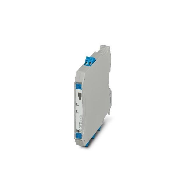
MACX MCR(-EX)-TS-I-OLP(-SP)(-C)
Loop-powered dual-channel temperature
transmitter
Data sheet
108133_en_00
1
© PHOENIX CONTACT 2017-09-21
Description
The device is a temperature transmitter with two input channels and HART® communication for conversion of different
input signals in a scalable analog 4 mA ... 20 mA output
signal.
The device contains two measuring inputs for
– Resistance thermometers (RTD)
– Thermocouples (TC)
– Resistance-type sensors (Ω)
– Voltage sensors (mV)
Features
–
–
–
–
–
–
Safe operation in the Ex area because of international
approvals
SIL certification according to IEC 61508:2010
Reliable measurement operation through sensor monitoring and device hardware error recognition
Diagnostic information according to NAMUR NE107
Diverse mounting variants and sensor connection combinations
Write protection for device parameters
The device can be snapped onto all 35 mm DIN rails according to EN 60715.
The device can be universally programmed via the USB interface of a PC prior to installation or during measurement
operation.
Make sure you always use the latest documentation.
It can be downloaded at phoenixcontact.net/products.
This document is valid for all products listed in Section "Ordering data" on page 4.
�MACX MCR(-EX)-TS-I-OLP(-SP)(-C)
Table of contents
1
Description.................................................................................................................................. 1
2
Ordering data.............................................................................................................................. 4
3
Technical data ............................................................................................................................ 5
3.1
3.2
4
Safety data MACX MCR-EX-TS-I-OLP(-SP)(-C) (Order No.: 2908660/2908661/1012248) ........................... 7
Input measuring ranges .................................................................................................................................. 8
Safety notes...............................................................................................................................14
4.1
4.2
4.3
4.4
4.5
MACX MCR-TS-I-OLP(-SP)(-C) (Order No.: 2908662/2908664/1012249) .................................................. 14
4.1.1 Installation notes ............................................................................................................................... 14
4.1.2 Installation in the potentially explosive area (Zone 2) ........................................................................ 14
MACX MCR-EX-TS-I-OLP(-SP)(-C) (Order No.: 2908660/2908661/1012248) ............................................ 15
4.2.1 Installation notes ............................................................................................................................... 15
4.2.2 Installation in the potentially explosive area ...................................................................................... 15
Occupational safety...................................................................................................................................... 16
Operational reliability.................................................................................................................................... 16
Product safety .............................................................................................................................................. 16
5
Scope of supply .........................................................................................................................16
6
Installation .............................................................................................................................................................. 16
6.1
6.2
6.3
6.4
6.5
6.6
6.7
7
Configuration .............................................................................................................................20
7.1
7.2
7.3
7.4
8
Transport and storage .................................................................................................................................. 16
Installation conditions ................................................................................................................................... 16
Installation dimensions ................................................................................................................................. 16
Mounting location ......................................................................................................................................... 16
Installation .................................................................................................................................................... 17
Installation check.......................................................................................................................................... 17
Electrical connection .................................................................................................................................... 17
6.7.1 Connecting the cables ...................................................................................................................... 18
6.7.2 Connection sensor cables................................................................................................................. 19
6.7.3 Connection signal line (supply) ......................................................................................................... 19
6.7.4 Connection inspection ...................................................................................................................... 19
Standard configuration ................................................................................................................................. 20
Configuration via software ............................................................................................................................ 20
HART® communication interface................................................................................................................. 21
Device status display.................................................................................................................................... 21
Startup .......................................................................................................................................22
8.1
8.2
8.3
8.4
8.5
108133_en_00
Installation check and switching on the device ............................................................................................. 22
General information on device configuration ................................................................................................ 22
Overview of operating possibilities ............................................................................................................... 22
Integrate transmitter via HART® protocol .................................................................................................... 22
8.4.1 HART® device variables and measured values ............................................................................... 22
8.4.2 Device variables and measured values............................................................................................. 23
8.4.3 Supported HART® commands ......................................................................................................... 23
Operating menu and parameter description ................................................................................................. 25
8.5.1 "Setup" menu .................................................................................................................................... 31
8.5.2 "Diagnostics" menu........................................................................................................................... 42
8.5.3 "Expert" menu ................................................................................................................................... 46
PHOENIX CONTACT
2 / 85
�MACX MCR(-EX)-TS-I-OLP(-SP)(-C)
9
Maintenance ..............................................................................................................................56
10 Troubleshooting ................................................................................................................................................... 56
10.1
10.2
Diagnostics results ....................................................................................................................................... 56
Overview of diagnostic events...................................................................................................................... 57
11 Disposal.....................................................................................................................................59
12 Safety function ...........................................................................................................................60
12.1
12.2
12.3
12.4
12.5
Definition of the safety function..................................................................................................................... 60
12.1.1 Safety-related output signal .............................................................................................................. 60
12.1.2 Dangerous undetected error in this analysis ..................................................................................... 60
12.1.3 Limit value monitoring ....................................................................................................................... 61
12.1.4 Safe measurement............................................................................................................................ 62
Restrictions for use in safety-related operation............................................................................................. 63
Safety measurement deviation ..................................................................................................................... 65
Restrictions of the device specification in safe operation ............................................................................. 67
Parameters and default settings for the increased parameter safety and expert mode ................................ 67
13 Use in safety equipment ............................................................................................................71
13.1
13.2
13.3
13.4
Device behavior in operation and in the event of a malfunction .................................................................... 71
13.1.1 Device behavior during power on...................................................................................................... 71
13.1.2 Device behavior during normal operation (SIL measuring mode)...................................................... 71
13.1.3 Device behavior in the case of demand of the safety function........................................................... 71
13.1.4 Safe states ........................................................................................................................................ 71
13.1.5 Device behavior in the event of alarms and warnings ....................................................................... 72
Device parameterization for safety-related applications ............................................................................... 72
13.2.1 Configuration of the measuring point ................................................................................................ 72
13.2.2 Increased parameterization safety mode, safe parameterization (SiPA) ........................................... 73
13.2.3 Expert mode, SIL mode activation (SiMA) ........................................................................................ 75
13.2.4 Deactivating SIL mode ...................................................................................................................... 76
Startup and repeat test ................................................................................................................................. 77
13.3.1 Repeat test of the safety function ...................................................................................................... 77
Startup or repeat test of the transmitter ........................................................................................................ 78
13.4.1 Test sequence A ............................................................................................................................... 79
13.4.2 Testing procedure C ......................................................................................................................... 80
14 Lifecycle ....................................................................................................................................81
14.1
14.2
14.3
14.4
14.5
14.6
14.7
Personnel requirements ............................................................................................................................... 81
Installation .................................................................................................................................................... 81
Startup.......................................................................................................................................................... 81
Operation ..................................................................................................................................................... 81
Maintenance................................................................................................................................................. 81
Repair........................................................................................................................................................... 81
Modification.................................................................................................................................................. 81
15 Measuring function .............................................................................................................................................. 82
15.1
15.2
Dual-channel functions................................................................................................................................. 82
Homogenous redundant SIL 3 configuration ................................................................................................ 82
16 Safety characteristics.................................................................................................................83
108133_en_00
PHOENIX CONTACT
3 / 85
�MACX MCR(-EX)-TS-I-OLP(-SP)(-C)
2
Ordering data
Products
Description
Type
Order No.
Pcs./Pkt.
The output-loop-powered temperature transmitter transmits up to two sensor
signals from RTD and TC sensors as well as from resistance-type sensors and
voltage sensors via the HART® communication or 4...20mA, configurable,
SIL2/3, screw connection
MACX MCR-TS-I-OLP
2908662
1
The output-loop-powered temperature transmitter transmits up to two sensor
signals from RTD and TC sensors as well as from resistance-type sensors and
voltage sensors via the HART® communication or 4...20mA, configurable,
SIL2/3, Push-in connection
MACX MCR-TS-I-OLP-SP
2908664
1
Output loop-powered temperature transducer, two universal inputs for therMACX MCR-TS-I-OLP-C
mocouples, resistance and voltage sensor, HART® communication, freely
configurable, installable in Zone 1, SIL 2/3, screw connection, ordering configuration
1012249
1
The output-loop-powered temperature transmitter transmits up to two sensor
signals from RTD and TC sensors as well as from resistance-type sensors and
voltage sensors via the HART® communication or 4...20mA, configurable,
SIL2/3, with intrinsic safety and screw connection
MACX MCR-EX-TS-I-OLP
2908660
1
The output-loop-powered temperature transmitter transmits up to two sensor
signals from RTD and TC sensors as well as from resistance-type sensors and
voltage sensors via the HART® communication or 4...20mA, configurable,
SIL2/3, with intrinsic safety and Push-in connection
MACX MCR-EX-TS-I-OLP-SP
2908661
1
1012248
1
Type
Order No.
Pcs./Pkt.
MCR PAC-T-USB
2309000
1
Documentation
Description
Type
Order No.
Pcs./Pkt.
Packing slip
MACX MCR-TS-I-OLP(-SP)(-C)
9076237
1
Packing slip
MACX MCR-EX-TS-I-OLP(-SP)(-C)
9076236
1
Output loop-powered temperature transducer, two universal inputs for therMACX MCR-EX-TS-I-OLP-C
mocouples, resistance and voltage sensor, HART® communication, freely
configurable, installable in Zone 1, SIL 2/3, with intrinsic safety and screw connection, ordering configuration
Accessories
Description
Programming adapter with USB and T port interface, 2.4 m for programming
FA MCR-..., MCR-...-LP-..., and MCR-...-HT-... modules
108133_en_00
PHOENIX CONTACT
4 / 85
�MACX MCR(-EX)-TS-I-OLP(-SP)(-C)
3
Technical data
Input data (see "Input measuring ranges" on page 8)
Resistance thermometers
Pt, Ni, Cu sensors: 2-, 3-, 4-wire
Thermocouple sensors
A, B, C, D, E, J, K, L, N, R, S, T, U
Linear resistance range
10 Ω ... 2000 Ω (minimum measurement range: 10 Ω)
Input voltage range
-20 mV ... 100 mV
Temperature measuring range
Range depending on the sensor type
-250 °C ... 2500 °C
Pt 100
-200 °C ... 850 °C
Measuring range span
Resistance thermometers
>10 K
Thermocouples
>50 K
Resistance
> 10 Ω
Voltage sensors (mV)
>5 mV
Output data
Output signal
HART®
4 mA ... 20 mA
20 mA ... 4 mA
Output signal maximum current
23 mA
HART® coding
FSK ±0.5 mA
HART® version
7
Transmission speed
1200 baud
Mains frequency filter
50/60 Hz
Load RB
(Ub max. -11 V) / 0.023 A (current output)
Load (Ω)
1348
1098
250
0
11 V 16.75 V
36.25 V 42 V
Ub
Supply voltage (V DC)
Communication resistance
≥250 Ω
Switch-on delay
HART®
approx. 10 s
Measured value
approx. 28 s
Residual ripple
Permanent residual ripple Uss ≤3 V for Ub ≥13.5 V, fmax. = 1 kHz
Connection data
Screw connection
Push-in connection
Conductor cross section, solid/stranded/AWG
0.2 mm² ... 2.5 mm²/
0.2 mm² ... 2.5 mm²/24 ... 14
0.2 mm² ... 1.5 mm²/
0.2 mm² ... 1.5 mm²/24 ... 16
Stripping length
7 mm
8 mm
Tightening torque
0.5 ... 06 Nm
-
Screw thread
M3
-
108133_en_00
PHOENIX CONTACT
5 / 85
�MACX MCR(-EX)-TS-I-OLP(-SP)(-C)
Failure information according to NAMUR NE43
Failure information is created when the measuring information is invalid or missing. A complete list of all of errors occurring in the measuring equipment is
issued.
Measuring value underrange
Linear drop of 4.0 mA ... 3.8 mA
Measuring value overrange
Linear increase from 20.0 mA ... 20.5 mA
Failure, e.g. sensor break, sensor short circuit
≤3.6 mA ("low") or ≥21 mA ("high") can be selected
The alarm setting "high" can be set between 21.5 mA and 23 mA, in this way
providing the necessary flexibility in order to fulfil the requirements of different
control systems. Only the alarm setting "low" is possible in SIL mode.
General data
Supply voltage range
Standard
12 V ... 42 V
SIL active
12 V ... 32 V
Ex
12 V ... 30 V
Maximum current consumption
≤23 mA
Step response (0 – 99 %)
Thermocouples
0.8 s
Resistance thermometers
0.9 s ... 1.3 s
Ambient temperature range
Operation
-40 °C to 85 °C
Operation (SIL active)
-40 °C ... 70 °C
Storage/Transport
-40 °C ... 100 °C
Humidity, non-condensing permitted
5 % ... 95 %
Maximum altitude for use above sea level
≤4000 m
Climatic class
B2
Degree of protection
IP20
Pollution degree
2
Overvoltage category
II
Electrical isolation of input/output
2 kV AC
Dimensions W / H / D
12.5 mm / 99 mm / 114.5 mm
Conformance / Approvals
CE compliant
ATEX
II 3G Ex nA IIC T6...T4 Gc (Order No.: 2908662/2908664/1012249)
II 2 (1) G Ex ib [ia Ga] IIC T6...T4 Gb (Order No.: 2908660/2908661/
1012248)
UL, USA/Canada
UL 61010 Recognized
CSA
See Control Drawing in the packing slip
FM
See Control Drawing in the packing slip
108133_en_00
PHOENIX CONTACT
6 / 85
�MACX MCR(-EX)-TS-I-OLP(-SP)(-C)
3.1
Safety data MACX MCR-EX-TS-I-OLP(-SP)(-C)
(Order No.: 2908660/2908661/1012248)
Technical data intrinsic safety
Supply circuit
Terminals 2.1, 2.2
Ui = 30 VDC
Ii = 130 mA
Pi = 770 mW
Ci = negligible
Li = negligible
UO = 9 VDC
IO = 13 mA
PO = 29.3 mW
Sensor circuit
Terminals 4.1, 4.2, 5.1, 5.2, 6.1, 6.2
Max. connection values
Ex ia IIC
Ex ia IIB
Ex ia IIA
CO = 0.93 μF
CO = 3.8 μF
CO = 4.8 μF
LO = 5 mH
LO = 20 mH
LO = 50 mH
T6 = -40 °C ... +46 °C
T5 = -40 °C ... +61 °C
T4 = -40 °C ... +85 °C
Temperature classes
Electrical connection values X Ex ib [ia Ga] IIC T6…T4 Gb Ub = 12 VDC ... 30 VDC
OUT = 4 mA ... 20 mA
Current consumption = ≤23 mA
Type of proctection (IEC)
Ex ib [ia Ga] IIC T6…T4 Gb
Hazardous location
Zone 0, 1, 2
EPL Ga, Gb, Gc
Zone 1, 2
EPL Gb, Gc
Nonhazardous location
Approved associated apparatus
2.1 2.2
Associated intrinsically
safe device with max.
connection values
according to table
e. g. RTD or TC sensor
(Simple Apparatus)
remote mounted
optional 2 channels
108133_en_00
MACX MCR-EX-TS-I-OLP
PWR
ERR
4.1 4.2
5.1 5.2
6.1 6.2
PHOENIX CONTACT
7 / 85
�MACX MCR(-EX)-TS-I-OLP(-SP)(-C)
3.2
Input measuring ranges
Table 1
Resistance thermometers and resistances
Standard
IEC 60751:2008
Designation
Measuring range
thresholds
Pt 100 (1)
–200 … +850 °C
Pt 200 (2)
(–328 … +1562 °F)
–200 … +850 C
Pt 500 (3)
Measurement deviation (±) Repeatability (±)
Digital 1
D/A 2
Digital 1
≤0.14 K (0.25 °F) 0.03 %
≤0.05 K (0.09 °F)
(4.8 μA)
≤0.86 K (1.55 °F)
≤0.13 K (0.23 °F)
(–328 … +1562 °F)
–200 … +500 °C
≤0.30 K (0.54 °F)
≤0.08 K (0.14 °F)
Pt 1000 (4)
(–328 … +932 °F)
–200 … +250 °C
≤0.14 K (0.25 °F)
≤0.05 K (0.09 °F)
JIS C1604:1984
Pt 100 (5)
(–328 … +482 °F)
–200 … +510 °C
≤0.12 K (0.22 °F)
≤0.04 K (0.07 °F)
DIN 43760 IPTS-68
Ni 100 (6)
(–328 … +950 °F)
–60 … +250 °C
≤0.09 K (0.16 °F)
≤0.03 K (0.05 °F)
Ni 120 (7)
(–76 … +482 °F)
–60 … +250 °C
≤0.07 K (0.13 °F)
≤0.03 K (0.05 °F)
Pt 50 (8)
(–76 … +482 °F)
–185 … +1100 °C
≤0.30 K (0.54 °F)
≤0.11 K (0.20 °F)
Pt 100 (9)
(–301 … +2012 °F)
–200 … +850 °C
≤0.14 K (0.25 °F)
≤0.05 K (0.09 °F)
Cu 50 (10)
(–328 … +1562 °F)
–180 … +200 °C
≤0.19 K (0.34 °F)
≤0.07 K (0.13 °F)
Cu 100 (11)
(–292 … +392 °F)
–180 … +200 °C
≤0.09 K (0.16 °F)
≤0.04 K (0.07 °F)
Ni 100 (12)
(–292 … +392 °F)
–60 … +180 °C
≤0.09 K (0.16 °F)
≤0.03 K (0.05 °F)
Ni 120 (13)
(–76 … +356 °F)
–60 … +180 °C
≤0.09 K (0.16 °F)
≤0.03 K (0.05 °F)
OIML R84: 2003,
GOST 6651-94
Cu 50 (14)
(–76 … +356 °F)
–50 … +200 °C
≤0.19 K (0.34 °F)
≤0.07 K (0.13 °F)
Resistance-type
sensor
Resistance Ω
(–58 … +392 °F)
10 ... 400 Ω
10 ...2000 Ω
40 mΩ
500 mΩ
15 mΩ
≤200 mΩ
GOST 6651-94
OIML R84: 2003,
GOST 6651-2009
–
–
1
Measured value transmitted with HART®
2
Percent values with regard to the configured measurement range of the analog output signal
3
Percent values with regard to the voltage range of the analog output signal
Connection method: 2-, 3-, or 4-wire termination,
sensor voltage: ≤0.3 mA
Possible for 2-wire conductor compensation of the cable resistance (0 Ω … 30 Ω)
108133_en_00
–
D/A 3
0.013 %
(2 μA)
For 3-, and 4-wire termination, sensor cable resistance
up to max. 50 Ω per cable
PHOENIX CONTACT
8 / 85
�MACX MCR(-EX)-TS-I-OLP(-SP)(-C)
Table 2
Standard
IEC 60584-1
Thermocouple and voltage sensor
Designation
Type A (W5ReW20Re) (30)
Type B (PtRh30PtRh6) (31)
Measuring range thresholds
0 … +2500 °C
Recommended
temperature
range
0 … +2500 °C
(+32 … +4532 °F)
+40 … +1820 °C
(+32 … +4532 °F)
+100 … +1500 °C
Measurement
deviation (±)
Digital 1 D/A 2
Repeatability (±)
≤1.62 K 0.03 %
(2.92 °F)
(4.8 μA)
≤2.02 K
(3.64 °F)
≤0.52 K 0.013 %
(0.94 °F)
(2 μA)
≤0.67 K
(1.21 °F)
(+104 … +3308 °F) (+212 … +2732 °F)
–270 … +1000 °C
0 … +750 °C
≤0.21 K
(0.38 °F)
(–454 … +1832 °F) (+32 … +1382 °F)
Type J (Fe-CuNi) –210 … +1200 °C
+20 … +700 °C
≤0.26 K
(35)
(0.47 °F)
(–346 … +2192 °F) (+68 … +1292 °F)
Type K (NiCr-Ni) –270 … +1372 °C
0 … +1100 °C
≤0.32 K
(36)
(0.58 °F)
(–454 … +2501 °F) (+32 … +2012 °F)
Type N (NiCrSi–270 … +1300 °C
0 … +1100 °C
≤0.43 K
NiSi) (37)
(0.77 °F)
(–454 … +2372 °F) (+32 … +2012 °F)
Type R (PtRh13- –50 … +1768 °C
0 … +1400 °C
≤1.92 K
Pt) (38)
(3.46 °F)
(–58 … +3214 °F)
(+32 … +2552 °F)
Type S (PtRh10- –50 … +1768 °C
0 … +1400 °C
≤1.9 K
Pt) (39)
(3.42 °F)
(–58 … +3214 °F)
(+32 … +2552 °F)
Type T (Cu-CuNi) –260 … +400 °C
–185 … +350 °C
≤0.32 K
(40)
(0.58 °F)
(–436 … +752 °F)
(–301 … +662 °F)
IEC 60584-1;
Type C (W5Re0 … +2315 °C
0 … +2000 °C
≤0.86 K
ASTM E988-96
W26Re) (32)
(1.55 °F)
(+32 … +4199 °F) (+32 … +3632 °F)
0 … +2000 °C
≤1.05 K
ASTM E988-96
Type D (W3Re0 … +2315 °C
W25Re) (33)
(1.89 °F)
(+32 … +4199 °F) (+32 … +3632 °F)
0 … +750 °C
≤0.26 K
DIN 43710
Type L (Fe-CuNi) –200 … +900 °C
(41)
(0.47 °F)
(–328 … +1652 °F) (+32 … +1382 °F)
Type U (Cu-CuNi) –200 … +600 °C
–185 … +400 °C
≤0.24 K
(42)
(0.43 °F)
(–328 … +1112 °F) (–301 … +752 °F)
GOST R8.8585- Type L (NiCr–200 … +800 °C
0 … +750 °C
≤2.27 K
20 01
CuNi) (43)
(4.09 °F)
(–328 … +1472 °F) (+32 … +1382 °F)
Voltage sensors (mV)
–20 … 100 mV
10 μV
Type E (NiCrCuNi) (34)
–
–
1
Measured value transmitted with HART®
2
Percent values with regard to the configured measurement range of the analog output signal
3
Percent values with regard to the voltage range of the analog output signal 4 .. 20 mA => 16 mA
Cold junction internal (Pt 100)
Cold junction external: Adjustable value
–40 °C … +85 °C (–40 °F … +185 °F)
108133_en_00
–
Digital 1 D/A 3
≤0.07 K
(0.13 °F)
≤0.08 K
(0.14 °F)
0.11 K
(0.20 °F)
≤0.16 K
(0.29 °F)
≤0.76 K
(1.37 °F)
≤0.74 K
(1.33 °F)
≤0.11 K
(0.20 °F)
≤0.33 K
(0.59 °F)
≤0.41 K
(0.74 °F)
≤0.07 K
(0.13 °F)
≤0.10 K
(0.18 °F)
≤0.15 K
(0.27 °F)
4 μV
Maximum sensor cable resistance 10 kΩ (SIL mode:
1 kΩ)
If the sensor cable resistance is greater than 10 kΩ, an
error message is issued according to NAMUR NE89.
PHOENIX CONTACT
9 / 85
�MACX MCR(-EX)-TS-I-OLP(-SP)(-C)
Sample calculation with Pt 100, measuring range 0 °C … +200 °C (+32 °F … +392 °F), ambient temperature 25 °C
(77 °F), supply voltage 24 V
Measurement deviation digital
Repeatability digital
Measurement deviation D/A = 0.03 % of 200 K (360 °F)
Repeatability D/A = 0.013 % of 200 K (360 °F)
Measurement deviation of digital value (HART®):
0.14 K (0.25 °F)
0.05 K (0.09 °F)
0.06 K (0.108 °F)
0.03 K (0.05 °F)
0.15 K (0.27 °F)
√(Measurement deviation digital² + repeatability digital²)
Measurement deviation of analog value (voltage output):
0.16 K (0.29 °F)
√(Measurement deviation digital² + repeatability digital² + measurement deviation D/A² +
repeatability D/A²)
In SIL mode, other measurement deviations apply
(see "Safety measurement deviation" on
page 65).
108133_en_00
PHOENIX CONTACT
10 / 85
�MACX MCR(-EX)-TS-I-OLP(-SP)(-C)
Operational influences
The information on the measurement deviation correspond
to an extended measuring insecurity of ±2 s (Gaussian normal distribution). Information under reference conditions.
Total measurement deviation of the transmitter at the voltage output = measurement deviation digital + measurement
deviation D/A.
Operational influences taken into account:
– Long-term drift
– Influence of the ambient temperature
– Influence of the supply voltage
Table 3
Resistance thermometers and resistances
Resistance
Designathermometer
tion
(RTD) according to standard
2-, 3-, 4-wire RTD
IEC 60751:2008 Pt 100 (1)
Pt 200 (2)
Pt 500 (3)
Pt 1000 (4)
JIS C1604:1984 Pt 100 (5)
DIN 43760 IPTS- Ni 100 (6)
68
Ni 120 (7)
GOST 6651-94 Pt 50 (8)
Pt 100 (9)
OIML R84: 2003, Cu 50 (10)
GOST 6651Cu 100 (11)
2009
Ni 100 (12)
Ni 120 (13)
OIML R84: 2003, Cu 50 (14)
GOST 6651-94
Resistance-type Resistance
sensor
Ω
Ambient temperature:
Supply voltage: Effect (±)
Effect (±) per 1 °C (1.8 °F) per V change
change
Long-term drift: Effect (±)
per year
Digital 1
D/A 2
≤0.02 K (0.04 °F) 0.001 %
≤0.03 K (0.05 °F)
≤0.01 K (0.02 °F)
Digital1
≤0.02 K (0.04 °F)
≤0.03 K (0.05 °F)
≤0.01 K (0.02 °F)
Digital 1
≤0.16 K (0.29 °F)
≤0.5 K (0.9 °F)
≤0.2 K (0.36 °F)
≤0.1 K (0.18 °F)
≤0.14 K (0.25 °F)
≤0.1 K (0.18 °F)
≤0.03 K (0.05 °F)
≤0.02 K (0.04 °F)
≤0.01 K (0.02 °F)
≤0.03 K (0.05 °F)
≤0.02 K (0.04 °F)
≤0.01 K (0.02 °F)
≤0.4 K (0.72 °F)
≤0.16 K (0.29 °F)
≤0.23 K (0.41 °F)
≤0.12 K (0.22 °F)
≤0.12 K (0.22 °F)
≤0.09 K (0.16 °F)
≤0.23 K (0.41 °F)
≤6 mΩ
≤30 mΩ
≤6 mΩ
≤30 mΩ
48 mΩ
290 mΩ
1
Measured value transmitted with HART®
2
Percent values with regard to the configured measurement range of the analog output signal
108133_en_00
D/A 2
0.001 %
D/A 2
0.017 %
PHOENIX CONTACT
11 / 85
�MACX MCR(-EX)-TS-I-OLP(-SP)(-C)
Table 4
Thermocouple and voltage sensor
Thermocouples
according to
standard
Designation
IEC 60584-1
Type A (W5ReW20Re) (30)
Type B (PtRh30PtRh6) (31)
Type E (NiCrCuNi) (34)
Type J (Fe-CuNi)
(35)
Type K (NiCr-Ni)
(36)
Type N (NiCrSiNiSi) (37)
Type R (PtRh13Pt) (38)
Type S (PtRh10Pt) (39)
Type T (Cu-CuNi)
(40)
IEC 60584-1;
Type C (W5ReASTM E988-96
W26Re) (32)
ASTM E988-96
Type D (W3ReW25Re) (33)
DIN 43710
Type L (Fe-CuNi)
(41)
Type U (Cu-CuNi)
(42)
GOST R8.8585- Type L (NiCr20 01
CuNi) (43)
Voltage sensors (mV)
Ambient temperature:
Effect (±) per 1 °C (1.8 °F)
change
Digital 1
D/A 2
≤0.13 K (0.23 °F) 0.001 %
Supply voltage: Effect (±) Long-term drift: Effect (±)
per V change
per year
≤0.01 K (0.02 °F)
≤0.01 K (0.02 °F)
≤1.7 K (3.06 °F)
≤0.03 K (0.05 °F)
≤0.03 K (0.05 °F)
≤0.2 K (0.36 °F)
≤0.04 K (0.07 °F)
≤0.04 K (0.07 °F)
≤0.04 K (0.07 °F)
≤0.04 K (0.07 °F)
Digital1
D/A 2
Digital 1
D/A 2
≤0.13 K (0.23 °F) 0.001 % ≤1.3 K (2.34 °F) 0.017 %
≤0.4 K (0.72 °F)
≤0.05 K (0.09 °F)
≤0.05 K (0.09 °F)
≤1.9 K (3.42 °F)
≤0.01 K (0.02 °F)
≤0.01 K (0.02 °F)
≤0.3 K (0.54 °F)
≤0.08 K (0.14 °F)
≤0.08 K (0.14 °F)
≤0.8 K (1.44 °F)
≤1 K (1.8 °F)
≤0.03 K (0.05 °F)
≤0.03 K (0.05 °F)
≤0.2 K (0.36 °F)
≤0.02 K (0.04 °F)
≤0.02 K (0.04 °F)
≤0.3 K (0.54 °F)
≤0.03 K (0.05 °F)
≤0.03 K (0.05 °F)
≤0.4 K (0.72 °F)
≤3 μV
≤3 μV
≤10 μV
1
Measured value transmitted with HART®
2
Percent values with regard to the configured measurement range of the analog output signal
108133_en_00
≤0.3 K (0.54 °F)
PHOENIX CONTACT
12 / 85
�MACX MCR(-EX)-TS-I-OLP(-SP)(-C)
Sample calculation with Pt 100, measuring range 0 °C … +200 °C (+32 °F … +392 °F), ambient temperature 35 °C
(95 °F), supply voltage 30 V
Measurement deviation digital
Repeatability digital
Measurement deviation D/A = 0.03 % of 200 K (360 °F)
Repeatability D/A = 0.013 % of 200 K (360 °F)
Influence of the ambient temperature (digital), 0.02 °C/K:
0.14 K (0.25 °F)
0.05 K (0.09 °F)
0.06 K (0.108 °F)
0.03 K (0.05 °F)
0.2 K (0.36 °F)
(35 °C -25 °C) x 0.02 °C/K
Influence of the ambient temperature (D/A), 0.001 %/K:
0.02 K (0.036 °F)
(35 °C -25 °C) x (0.001 % of 200 °C)
Influence of the supply voltage (digital), 0.02 K/V:
0.12 K (0.216 °F)
(30 V -24 V) x 0.02 K/V
Influence of the supply voltage (D/A), 0.001 %/V:
0.012 K (0.0216 °F)
(30 V -24 V) x (0.001 % of 200 °C)
Measurement deviation of digital value (HART®):
0.28 K (0.50 °F)
√(Measurement deviation digital² + repeatability digital² + influence ambient temperature (digital)²
+ influence supply voltage (digital)²)
Measurement deviation of analog value (voltage output):
0.29 K (0.52 °F)
√(Measurement deviation digital² + repeatability digital² + measurement deviation D/A² + repeatability D/A² + influence ambient temperature (digital)² + influence ambient temperature (D/A)² +
influence supply voltage (digital)²) + influence supply voltage (D/A)²)
108133_en_00
PHOENIX CONTACT
13 / 85
�MACX MCR(-EX)-TS-I-OLP(-SP)(-C)
4
Safety notes
4.1.2
4.1
MACX MCR-TS-I-OLP(-SP)(-C) (Order No.:
2908662/2908664/1012249)
•
4.1.1
Installation notes
•
•
•
•
•
•
•
•
•
•
•
•
The category 3 device is designed for installation in
Zone 2 potentially explosive areas. It meets the requirements of EN 60079-0:2012 and EN 60079-15:2010.
Only qualified specialist personnel may install, start up,
and operate the device.
Follow the installation instructions as described.
Install the device according to the manufacturer's information and the valid standards and regulations (e.g.
EN/IEC 60079-14).
When installing and operating the device, the applicable regulations and safety directives (including national
safety directives), as well as the general codes of practice, must be observed. The technical data is provided
in this packing slip and on the certificates (conformity
assessment, additional approvals where applicable).
Do not open or make changes to the device.
Make sure when installing the device that IP20 protection for housing in accordance with EN/IEC 60529 is observed.
Do not repair the device yourself; replace it with an
equivalent device instead. Repairs may only be carried
out by the manufacturer. The manufacturer is not liable
for damage resulting from noncompliance.
The device complies with the EMC regulations for industrial areas (EMC class B). When used in residential
areas, the device may cause radio interference.
Operate the device only under the approved ambient
conditions.
Operate the device only in a faultless and operationally
reliable state.
Do not use the programming interface for configuration
in a potentially explosive area.
108133_en_00
•
•
•
•
•
•
•
•
Installation in the potentially explosive area
(Zone 2)
Observe the specified conditions for use in potentially
explosive areas! Install the device in a suitable, approved housing that meets the requirements of IEC/
EN 60079-15 and has at least IP54 protection. Also observe the requirements of IEC/EN 60079-14.
Only devices that are designed for operation in Ex zone
2 and are suitable for the conditions at the installation
location may be connected to the circuits in Zone 2.
In potentially explosive areas, only connect and disconnect cables when the power is disconnected.
The device has to be stopped and immediately removed from the Ex area if it is damaged, was subjected
to an impermissible load, stored incorrectly, or if it malfunctions.
Use suitable cables for the operation of the field transmitter housing at an ambient temperature below –20 °C
and approved cable entries for this application.
Connect the housing to the equipotential bonding line.
During installation ensure that the used housing and cable glands correspond to the requirements of the IEC/
EN 60079-0 for category 3 or group III housing.
At ambient temperatures above +70 °C, use suitable
heat-resistant cables, cable entries, and seals whose
operating temperature is Ta +5 K above the ambient
temperature.
Set up the device in such a way that even in infrequent
cases an ignition source through impact or friction between metal/steel and the housing is eliminated.
PHOENIX CONTACT
14 / 85
�MACX MCR(-EX)-TS-I-OLP(-SP)(-C)
4.2
MACX MCR-EX-TS-I-OLP(-SP)(-C) (Order No.:
2908660/2908661/1012248)
4.2.1
4.2.2
•
Installation notes
•
•
•
•
•
•
•
•
•
•
•
•
•
The category 3 device is designed for installation in
Zone 2 potentially explosive areas. It meets the requirements of EN 60079-0:2012 and EN 60079-15:2010.
Only qualified specialist personnel may install, start up,
and operate the device.
Follow the installation instructions as described.
Install the device according to the manufacturer's information and the valid standards and regulations (e.g.
EN/IEC 60079-14).
When installing and operating the device, the applicable regulations and safety directives (including national
safety directives), as well as the general codes of practice, must be observed. The technical data is provided
in this packing slip and on the certificates (conformity
assessment, additional approvals where applicable).
Do not open or make changes to the device.
Make sure when installing the device that IP20 protection for housing in accordance with EN/IEC 60529 is observed.
Do not repair the device yourself; replace it with an
equivalent device instead. Repairs may only be carried
out by the manufacturer. The manufacturer is not liable
for damage resulting from noncompliance.
The device complies with the EMC regulations for industrial areas (EMC class B). When used in residential
areas, the device may cause radio interference.
Operate the device only under the approved ambient
conditions.
Operate the device only in a faultless and operationally
reliable state.
Do not use the programming interface for configuration
in a potentially explosive area.
•
•
•
•
In potentially explosive areas, only connect and disconnect cables when the power is disconnected.
The device has to be stopped and immediately removed from the Ex area if it is damaged, was subjected
to an impermissible load, stored incorrectly, or if it malfunctions.
During installation make sure that the safety distance
between the intrinsic safety and the non-intrinsically
safe circuits amounts to 50 mm.
When interconnecting the measuring device with certified intrinsically safe circuits of the category "ib" with the
explosion protection group IIC or IIB, the type of protection changes: Ex ib IIC or Ex ib IIB.
Do not use the programming interface for configuration
in a potentially explosive area.
Connect the device (connection head) to the potential
equalization conductor.
Safety notes for zone 1 and zone 2
•
•
•
•
•
•
108133_en_00
Installation in the potentially explosive area
The device is approved for intrinsically safe (Ex i) circuits up to Zone 0 (gas) in the Ex area. Observe the
safety values for intrinsically safe equipment and the
connecting cables during connection (IEC/EN 6007914); the values specified in these installation notes and
the EC-type examination certificate must be observed.
Install the device in such a way that it meets at least protection class IP20.
When carrying out measurements on the intrinsically
safe side, observe the relevant regulations regarding
the connection of intrinsically safe equipment. In intrinsically safe circuits, only use measuring devices that
are approved for these circuits.
If the device has been used in non-intrinsically safe circuits, it must not be used again in intrinsically safe circuits. The device must be clearly marked as nonintrinsically safe.
The device may be used in accordance with the manufacturer's information in Zone 1 (category 2) GB or
Zone 2 (category 3) GC.
The safe sensor circuit may be inserted into Zone 0
(category 1) GA.
PHOENIX CONTACT
15 / 85
�MACX MCR(-EX)-TS-I-OLP(-SP)(-C)
4.3
Occupational safety
When working on and with the device, wear the required
personal safety equipment as stipulated by national regulations.
4.4
Operational reliability
Risk of injury
– Only operate the device when it has no errors and is in
an operationally reliable condition.
– The operator is responsible for error-free operation of
the device.
4.5
Product safety
This measuring device has been built and tested for operational reliability in line with the latest technology and good
engineering practice. The device left the factory in safe and
error-free condition.
The device fulfils general safety and legal requirements.
6
Installation
6.1
Transport and storage
Please note the following points:
• Pack the device for storage and transport so that it is
protected against impact. The original packing provides
optimal protection for this.
• The permissible storage temperature is
-40 °C … +100 °C (-40 °F … +212 °F).
6.2
Installation conditions
Operating temperature range:
– -40 °C … +85 °C (–40 °F … 185 °F)
– SIL operation: –40 °C … 70 °C (-40 °F … 158 °F)
6.3
Installation dimensions
The device complies with the EC directives that are listed in
the device-specific EC declaration of conformity. By affixing
the CE mark, Phoenix Contact confirms this situation.
99
12,5
7
Scope of supply
The scope of supply of the device consists of:
– Temperature transmitter
– Packing slip with installation and safety notes and initial
commissioning
114,5
5
116 (SP)
112,5
Figure 1
6.4
Dimensions
Mounting location
The device can be snapped onto all 35 mm DIN rails according to EN 60715.
108133_en_00
PHOENIX CONTACT
16 / 85
�MACX MCR(-EX)-TS-I-OLP(-SP)(-C)
6.5
Installation
Sensor
IN
NOTE: Electrostatic discharge
2
Interface /
PLC / DCS
OUT
1
4.1 4.1
Take protective measures against electrostatic
discharge before opening the front cover!
5.1 5.1
6.1 6.1
2.2
-
2.1
+
4.2 4.2
5.2 5.2
6.2 6.2
Figure 2
Terminal connection assignment MACX MCRTS-I-OLP(-SP)(-C) (Order No.: 2908662/
2908664/1012249)
Sensor
IN
An ME 6,2 TBUS-2 DIN rail connector (Order No.: 2869728)
is used to supply active devices. A DIN rail connector is not
required to operate this passive device.
2
1
5.1 5.1
6.1 6.1
6.7
2.2
-
4.2 4.2
2.1 +
5.2 5.2
6.2 6.2
•
•
Interface /
PLC / DCS
OUT
4.1 4.1
This device can be snapped onto a DIN rail connector – an
electrically conductive connection is not established. This
means that you do not need to disconnect an existing DIN
rail connector element connection.
6.6
HHT
HHT
Installation check
Is the device undamaged (visual inspection)?
Do the ambient conditions correspond to the device
specification?
Electrical connection
WARNING: Risk of electric shock
Zone 1,2
Figure 3
Zone 1,2
Terminal connection assignment MACX MCREX-TS-I-OLP(-SP)(-C) (Order No.: 2908660/
2908661/1012248)
A minimum load of 250 Ω is required in the signal circuit for
device operation via the HART® protocol (terminals 1 and
2).
Keep the device off the power supply when making electrical connections.
NOTE: Damage to the device by high-energy
transients
NOTE: Damage to the electronics
Provide suitable upstream surge protection.
Assign the programming interface only with the
programming adapter.
Violation can lead to the destruction of the electronics.
108133_en_00
PHOENIX CONTACT
17 / 85
�MACX MCR(-EX)-TS-I-OLP(-SP)(-C)
6.7.1
Connecting the cables
Screw connection
AWG 24-14
2
0,2-2,5 mm
MACX MCR-...
A
7 mm
B
Figure 4
•
•
•
0,5-0,6 Nm
5-7 lb In
Screw connection
Strip the conductor by 7 mm and crimp with ferrules.
Insert the conductor into the corresponding connection
terminal block.
Use a screwdriver to tighten the screw in the opening
above the connection terminal block.
Tightening torque: 0.6 Nm
Push-in connection
Figure 5
•
•
•
Push-in connection
Strip the conductor by 8 mm and crimp with ferrules.
Insert the conductor into the corresponding connection
terminal block.
Push in the pushbutton with a screwdriver to release.
108133_en_00
PHOENIX CONTACT
18 / 85
�MACX MCR(-EX)-TS-I-OLP(-SP)(-C)
6.7.2
Connection sensor cables
NOTE: Invalid measured values
Make sure that while connecting the two sensors
there is no direct connection between the sensors
(e.g. through the grounding of both sensors).
The resulting compensating currents lead to considerable distortions of the measurement.
If you cannot ensure this, then you must use two
measuring transducers.
The following assignments are possible:
Sensor input 1
RTD or resistance- RTD or resistance- RTD or resistance- Thermocouple
type sensor, 2-wire type sensor, 3-wire type sensor, 4-wire (TC), voltage transmitter
Sensor input 2 RTD or resistance- Yes
Yes
No
Yes
type sensor, 2-wire
RTD or resistance- Yes
Yes
No
Yes
type sensor, 3-wire
RTD or resistance- No
No
No
No
type sensor, 4-wire
Thermocouple
Yes
Yes
Yes
Yes
(TC), voltage transmitter
6.7.3
Connection signal line (supply)
Without HART® communication, a normal installation cable
is sufficient.
With HART® communication, we recommend a shielded
cable.
The signal line connectors (2.1 + and 2.2 -) are protected
against polarity reversal.
6.7.4
•
•
•
•
•
•
•
108133_en_00
Connection inspection
Is there any damage to the device or cables?
Does the supply voltage comply with the specifications
on the rating plate?
Are the cables installed strain-free?
Are the auxiliary energy and signal cables correctly
connected?
Are all the screw terminal blocks securely tightened and
the connections of the spring clamps checked?
Are all the cable entries mounted, securely tightened
and sealed?
Are all the housing covers mounted and securely tightened?
PHOENIX CONTACT
19 / 85
�MACX MCR(-EX)-TS-I-OLP(-SP)(-C)
7
7.1
Configuration
Setting the communication connection
When you create a new project in your FDT/DTM
program, you have to select once the communication connection in the configuration window.
Standard configuration
To change the configuration data via PC, use the programming adapter MCR-PACT-T-USB (Order. No.: 2309000)
and the FDT/DTM solution, which is available free of charge
at phoenixcontact.net/products.
The device is supplied with the following standard configuration:
To do this, proceed as follows:
• Load the DTM for the programming adapter MCR-PACT-USB in your project.
• Right-click on the MCR-PAC-T-USB. Select "Configuration".
Sensor input 1 active , Pt 100 3-wire, -200 °C ...850 °C,
sensor input 2 inactive
7.2
Configuration via software
CAUTION: Undefined behavior of output and
relays during parameterization possible
Do not parameterize the device while a process is
running.
The "Configuration" window opens.
Use the MCR-PAC-T-USB programming adapter
(Order No.: 2309000) for connecting with the device, or one of the possibilities from Section
"Overview of operating possibilities" on page 22.
PC software configuration interface
To configure the device using the software solution, connect
the device to your PC. This requires the MCR-PAC-T-USB
programming adapter (Order No.: 2309000) and the FDT /
DTM software packages, which already contain the driver
for the programming adapter.
The software solution can be downloaded free of charge
from the following address: phoenixcontact.net/products.
Be sure to download and install both the FDT framework application and the DTM package.
108133_en_00
•
•
•
In the field "Selected COM port", select the entry "USB
Serial Port (COM xxx)".
Confirm your selection with "Enter".
Load the DTM of the display into your project.
Communication is established.
PHOENIX CONTACT
20 / 85
�MACX MCR(-EX)-TS-I-OLP(-SP)(-C)
7.3
HART® communication interface
The configuration of HART® functions as well as devicespecific parameters is via the HART® communication or the
service interface of the device. For this, there are special
configuration tools on offer from different manufacturers.
For further information, contact the Phoenix Contact sales
employee assigned to you.
7.4
Device status display
The device has the following operating and indication elements.
1
PH
OEN
Flac
32 hsmIX C
O
82
5 Blarkt NTA
om str. CT
be 8 Gm
rg,
bH
Ger
&C
man
o.
KG
y
12
PH
OEN
Flac
32 hsmIX C
O
82
5 Blarkt NTA
om str. CT
be 8 Gm
rg,
bH
Ger
&C
man
o.
KG
y
19
2.2
2.1
2.1
2.2
L
L
MA
MA
Su OO
Su OO
C
C
pp P P
pp P P
Ord X M
Ord X M
ow
ow
,2 ly
... ly
.-N CR
.-N CR
Cla 30V Volt ere
Ou ... 30VVolt ere
ss
D
ag d T www o.: -EXtpu DC age d T www o.: 2 -EX-T
2 ci C
T
0/4
29
e:
T
em .ph
em .ph
9
:
rc
pe oenix 086 S-I-O HA ... 20 t 1/2
pe oenix 086 S-I-O
Ou-40 °.. uit o
ra
ratu co
mA
6
61
R
co
r
P
PL
.+
0
ture nta
LU T on
4 ... tpu
85 SELV
-S
re ntact
ly
=
°C
P
Tra ct.co
Tra .co
25 o n
Inp20 mtA
T
/ - circu
m
OU
40
ns
ns m
it
-2 3V
° ...
du
du
RT ut / 20
In 0°...+ AC, 1 T 1
...
D,
+1
ce
ce
4m
TC
85
r H 0/4put 60°C/-25V D
rH
,m
A
°F
4°+ C
AR ...
AR
V,
R
14
20
T
T
Ma m A
0°F
x. V
2.2
alu
2.1
4.1
e
4.2 Zon s
am
b
m
am
b
IN
5.2
4.2
6.1
5.1
4.1
ST PAR
AL AT
LE E W
D IN H
EN
ZO
NE ENER
2
GIZ
PW
ED
R
ER
ED
1
2
3
4
5
+
PW
5.2
4.2
6.1
5.1
R
R
ER
4.1
IN
IN
4.2
4.1 5.2
5.1 6.2
6.1
Figure 6
6.2
2.2
2.2
R
MACX MCR-EX-TS-I-OLP
+
6.2
2.1
2.1
OUT
se
e
DO man
ua
AN NO
l
D INT SE
ST PA
AL RAT
LE E
D IN W
H
ZO EN
NE EN
2 ERG
IZ
PWR
G
1.1
+
-
NIN
OUT
WAR
:U eD
O
, iv.
V
O
oc
=
25
5.2 PO , SC
,2
:U
V
P
2.2
i ,
O
V = 58
li
7
, max
se lma = 30 mW
WAR
em x = V
an
DO NIN
u a 150
N G
mA
l
AN OT
SE
D
- 5.1
MACX MCR-EX-TS-I-OLP-SP
HHT
PWR
2.1
OUT
HHT
OUT
5
2
3
4
4.2
4.1 5.2
5.1 6.2
6.1
Operating and indication elements
COMBICON pluggable screw or Push-in connection
terminal block
Service interface
Green "PWR" LED for power supply
Red "ERR" LED as error display
Snap-on foot for DIN rail mounting
LED
PWR
ERR
Color / status
Green
On
Red
Flashing
On
Description
Supply voltage
Supply voltage is present
Diagnostics
Diagnostic message from
category C, S or M
Diagnostic message from
category F
A description of the categories can be found in "Status signals" on page 56.
108133_en_00
PHOENIX CONTACT
21 / 85
�MACX MCR(-EX)-TS-I-OLP(-SP)(-C)
8
8.1
Startup
8.4
Installation check and switching on the device
For HART® communication, measured values are transmitted from the transmitter via the HART® protocol to a connected control system where they are processed further.
Perform all final checks before starting up the device.
– Checklist "Installation check" on page 17
– Checklist "Connection inspection" on page 19
Table 1
Integrate transmitter via HART® protocol
Version data of the device
Firmware version
01.01.zz On rating plate
During initial startup of the device, program the setup according to the description in the following sections.
8.2
General information on device configuration
You can start up and parameterize your device as follows:
– Via the HART® protocol
– Via the MCR PAC-T-USB adapter per PC
8.3
Overview of operating possibilities
1
4
3
2
5
Firmware version parameters
Manufacturer ID 0xB0
Diagnostics, Device information, Firmware version
Manufacturer ID parameters
Device type ID
Diagnosis, device info, manufacturer ID
Device type parameters
MACX
MCRDiagnosis, device info, device
(EX)-TStype
I-OLP(SP)(-C)
HART® protocol 7.0
--revision
Device revision 2
On transmitter rating plate
6
Device revision parameters
Diagnosis, device info, device
revision
PHOEN
Flachs
IX
32825 markts
CONTA
Blomb
2.2
Flachs
32825 markts
2.1
tr. CT
erg,8 GmbH
Blomb
tr.
erg,8
LOO Germa &
MAC
Germa
Sup
Sup
Co.
KG
ny
19,2 ply
ply P Pow ny
Ord X MCR
...
...
.-No Class30V Volt ered
Outp
30VVolt
TS
www.
DC age
age
Tem phoen.: 2908 -I2 circui
T
0/4
ut DC
:
:
...
-40
pera ixcon 662OPL HART
20mA1/2
Outp
t or
°..
ture tact.c
4 ... ut .+ 85 SELV
U
only
=
°C
20
Tran om
253V on
Inpu
T
/ - circui
mA
40
-20°.. AC,OUT
sduc
° ... t
t / 20 ...
Inpu .+60°C
125V1
+1
4 mA
er
TC,
85
0/4 t
°F
HAR
mV,
/-4°+1DC
...
R
T 20mA
40°F
Max
. Valu
4.1
es
4.2: Zone
8.4.1
12
amb
m
amb
RTD,
+
,
O
4.2
6.1
mA
PWR
ATE
LED WHEN
IN
ZONE ENERG
2
5.1
4.1
IZED
IZED
ERR
IN
4.2
4.1 5.2
5.1 6.2
6.1
7
Figure 7
1
2
3
4
5
6
7
The device variables are assigned the following measured
values by default.
Overview of operating possibilities
PLC (Programmable logic controller)
Measuring transducer supply device, e.g. MACX MCREX-SL-RPSSI-I-SP (Order No.: 2924016) (with communication resistance)
Handheld, e.g. from Fisher Rosemount
PC with operating tool (e.g. M&M Container or IFS
Conf)
HART® modem
Programming adapter MCR-PAC-T-USB (Order No.:
2309000)
Temperature transmitter
108133_en_00
HART® device variables and measured values
1.1
+
150
SEPAR
INSTAL
5.2
-
al
6.2
ENERG
2
2.2
oc
=
25,2
5.2: PO , SC
V
U
P
i ,
O
V = 587
li
, max =
30 mW
V
WARN see lmax
manu =
DO ING
NOT
AND
LEDATE
IN WHEN
ZONE
2.1
Div.
V
OUT
PWR
O
2.2
ING see
DO manua
ANDNOT l
SEPAR
INSTAL
MACX MCR-TS-I-OLP
HHT
OUT
U
- 5.1
2.1
WARN
Device variable
PV
SV
TV
QV
Measured value
Sensor 1
Device temperature
Sensor 1
Sensor 1
The assignment of the device variables to the process variable can be changed in the following
menu:
Expert, Communication, HART output
PHOENIX CONTACT
22 / 85
�MACX MCR(-EX)-TS-I-OLP(-SP)(-C)
8.4.2
Device variables and measured values
The individual device variables are assigned the following
measured values:
Device variable
0
1
2
3
4
5
6
7
Measured values
Sensor 1
Sensor 2
Device temperature
Mean value from sensor 1 and sensor
2
Difference from sensor 1 and sensor 2
Sensor 1 (backup sensor 2)
Sensor 1 with switchover to sensor 2 if
a limit value is exceeded
Mean value from sensor 1 and sensor
2 with backup
The device variables can be retrieved from a
HART® master via HART® command 9 or 33.
8.4.3
Supported HART® commands
The HART® protocol makes possible transmission of measured and device data between HART® master and the corresponding field device for configuration and diagnosis purposes. HART® masters, e.g., the hand-held operator panel
or PC-based operating programmed (e.g. M&M Container)
require device description files (DD = Device Descriptions,
DTM) that help enable access to all information in a HART®
device. Transmission of such information is solely via "commands".
Universal commands:
Universal commands are supported and used by all
HART® devices.
Connected functions include the following:
– Detection of HART® devices
– Reading digital measured values
Common practice commands:
The common practice commands provide functions that can
be supported or executed by many but not all field devices.
Device-specific commands:
This commands allow access to device-specific functions
that are not standardized for HART®. These commands access individual field device information.
108133_en_00
Command no.
Designation
Universal commands
0, Cmd0
Read unique identifier
1, Cmd001
Read primary variable
2, Cmd002
Read loop current and percent of range
3, Cmd003
Read dynamic variables and loop current
6, Cmd006
Write polling address
7, Cmd007
Read loop configuration
8, Cmd008
Read dynamic variable classifications
9, Cmd009
Read device variables with status
11, Cmd011
Read unique identifier associated with
TAG
12, Cmd012
Read message
13, Cmd013
Read TAG, descriptor, date
14, Cmd014
Read primary variable transducer information
15, Cmd015
Read device information
16, Cmd016
Read final assembly number
17, Cmd017
Write message
18, Cmd018
Write TAG, descriptor, date
19, Cmd019
Write final assembly number
20, Cmd020
Read long TAG (32-byte TAG)
21, Cmd021
Read unique identifier associated with
long TAG
22, Cmd022
Write long TAG (32-byte TAG)
38, Cmd038
Reset configuration changed flag
48, Cmd048
Read additional device status
Common practice commands
33, Cmd033
Read device variables
34, Cmd034
Write primary variable damping value
35, Cmd035
Write primary variable range values
36, Cmd036
Set primary variable upper range value
37, Cmd037
Set primary variable lower range value
40, Cmd040
Enter/Exit fixed current mode
42, Cmd042
Perform device reset
44, Cmd044
Write primary variable units
45, Cmd045
Trim loop current zero
46, Cmd046
Trim loop current gain
50, Cmd050
Read dynamic variable assignments
51, Cmd051
Write dynamic variable assignments
54, Cmd054
Read device variable information
59, Cmd059
Write number of response preambles
103, Cmd103
Write burst period
104, Cmd104
Write burst trigger
105, Cmd105
Read burst mode configuration
PHOENIX CONTACT
23 / 85
�MACX MCR(-EX)-TS-I-OLP(-SP)(-C)
Command no.
107, Cmd107
108, Cmd108
109, Cmd109
108133_en_00
Designation
Write burst device variables
Write burst mode command number
Burst mode control
PHOENIX CONTACT
24 / 85
�MACX MCR(-EX)-TS-I-OLP(-SP)(-C)
8.5
Operating menu and parameter description
The following table lists all parameters that contain the operating menus "Setup", "Diagnosis", and "Expert". The page
numbers refer to the description of the corresponding parameter.
Not all submenus and parameters are available in every device depending on the parameterization. Details of this are
given with the description of the parameters under the "Prerequisite" category.
The parameter groups for the expert setup contain all parameters of the operating menu "Setup", "Diagnosis", as
well as additional parameters that are exclusively reserved
for the experts.
The parameterization in SIL mode is different from standard
mode and is described in "Use in safety equipment" on
page 71.
Setup,
Setup,
Advanced. Setup,
Setup,
Advanced. Setup,
108133_en_00
Sensors,
Measuring point designation
Unit
Sensor type 1
Connection method 1
2-wire compensation 1
Cold junction 1
Cold junction preset value 1
Sensor type 2
Connection method 2
2-wire compensation 2
Cold junction 2
Cold junction preset value 2
Current output assignment (PV)
Start of measuring range
End of measuring range
on page 31
on page 31
on page 31
on page 31
on page 31
on page 32
on page 32
on page 31
on page 31
on page 31
on page 32
on page 32
on page 32
on page 33
on page 33
Enter release code
Operating software access rights
Interlock status
Device temperature alarm
on page 34
on page 34
on page 34
on page 34
Sensor offset 1
Sensor offset 2
Corrosion detection
Drift/Difference monitoring
Drift/Difference alarm category
Drift/Difference alarm delay
Drift/Difference limit value
Sensor switchover limit value
on page 35
on page 35
on page 35
on page 35
on page 35
on page 36
on page 36
on page 36
PHOENIX CONTACT
25 / 85
�MACX MCR(-EX)-TS-I-OLP(-SP)(-C)
Setup,
Advanced. Setup,
Current output,
Output current
Measuring mode
Out of range category
Error handling
Residual current
Voltage trim 4 mA
Voltage trim 20 mA
on page 36
on page 37
on page 37
on page 37
on page 37
on page 37
on page 37
Setup,
Advanced. Setup,
Display,
Interval display
Format display
1st display value
1st decimal places
2nd display value
2nd decimal places
3rd display value
3rd decimal places
on page 38
on page 38
on page 38
on page 38
on page 39
on page 39
on page 39
on page 39
Setup,
Advanced. Setup,
SIL,
SIL option
Operating state
Enter SIL checksum
Time stamp SIL parameterization
SIL startup mode
SIL HART mode
Force safe state
on page 40
on page 40
on page 40
on page 40
on page 40
on page 41
on page 41
Setup,
Advanced. Setup,
Administration,
Reset device
Define write-protect code
on page 41
on page 41
Diagnostics,
Current diagnostics
Troubleshooting measure
Last diagnostics 1
Operating time
on page 42
on page 42
on page 42
on page 42
Diagnostics, Diagnostic list,
Number of current diagnostic messages
Current diagnostics
Current diagnostics channel
on page 43
on page 43
on page 43
Diagnostics, Event log,
Last diagnostics n
Last diagnostics channel n
on page 43
on page 43
Diagnostics,
Measuring point designation
Serial number
Firmware version
Device name
Configuration counter
108133_en_00
Device information,
on page 44
on page 44
on page 44
on page 44
on page 44
PHOENIX CONTACT
26 / 85
�MACX MCR(-EX)-TS-I-OLP(-SP)(-C)
Diagnostics, Measured values,
Value sensor 1
Value sensor 2
Device temperature
on page 44
on page 44
on page 44
Diagnostics, Measured values, Min./Max. values,
Sensor n min. value
Sensor n max. value
Reset min./max. values sensor
Device temperature min.
Device temperature max.
Reset device temperature max./min.
on page 45
on page 45
on page 45
on page 45
on page 45
on page 45
Diagnostics, Simulation,
Simulation current output
Current output value
on page 46
on page 46
Expert,
Enter release code
Operating software access rights
Interlock status
on page 34
on page 34
on page 34
Unit
Attenuation
Alarm delay
Mains frequency filter
Device temperature alarm
on page 31
on page 46
on page 46
on page 46
on page 46
Expert,
System,
Expert, System,
Display,
Interval display
Format display
1st display value
1st decimal places
2nd display value
2nd decimal places
3rd display value
3rd decimal places
on page 38
on page 38
on page 38
on page 38
on page 39
on page 39
on page 39
on page 39
Expert, System,
Administration,
Reset device
Define write-protect code
on page 41
on page 41
Expert,
Sensor n 1,
Sensor type n
Connection method n
2-wire compensation n
Cold junction n
Cold junction preset value
Sensor offset n
Lower sensor limit n
Upper sensor limit n
Serial number sensor
on page 31
on page 31
on page 31
on page 32
on page 32
on page 35
on page 47
on page 47
on page 47
1
Sensors,
n = number of sensor inputs (1 and 2)
108133_en_00
PHOENIX CONTACT
27 / 85
�MACX MCR(-EX)-TS-I-OLP(-SP)(-C)
Expert,
1
Sensor trim
Sensor trim initial value
Sensor trim final value
Sensor trim min. range
on page 47
on page 48
on page 48
on page 48
Lower sensor limit n
Upper sensor limit n
Call.-V. Dusen coeff. R0, A,B, C
Polynomial coeff. R0, A, B
on page 48
on page 48
on page 49
on page 49
Corrosion detection
Drift/Difference monitoring
Drift/Difference alarm category
Drift/Difference alarm delay
Drift/Difference limit value
Sensor switchover limit value
Calibration counter start
Calibration counter alarm category
Calibration counter start value
Countdown calibration
on page 35
on page 35
on page 35
on page 36
on page 36
on page 36
on page 49
on page 49
on page 49
on page 50
Output current
Measuring mode
Start of measuring range
End of measuring range
Out of range category
Error handling
Residual current
Voltage trim 4 mA
Voltage trim 20 mA
on page 36
on page 37
on page 33
on page 33
on page 37
on page 37
on page 37
on page 37
on page 37
Measuring point designation
HART short description
HART address
Preamble number
Configuration changed
Configuration changed, reset flag
on page 44
on page 50
on page 50
on page 50
on page 50
on page 51
n = number of sensor inputs (1 and 2)
Expert,
1
Sensor n, 1 Sensor trim,
Sensors,
Sensor n 1, Linearization,
Sensors,
n = number of sensor inputs (1 and 2)
Expert,
Sensors,
Expert,
Output,
Expert,
Communication,
108133_en_00
Diagnostics settings,
HART configuration,
PHOENIX CONTACT
28 / 85
�MACX MCR(-EX)-TS-I-OLP(-SP)(-C)
Expert,
Communication, HART info,
Device type
Device revision
HART revision
HART description
HART message
Hardware revision
SWRev
HART date
on page 51
on page 51
on page 51
on page 51
on page 52
on page 52
on page 52
on page 52
Expert,
Communication,
Current output assignment (PV)
PV
Assignment SV
SV
Assignment TV
TV
Assignment QV
QV
on page 32
on page 52
on page 52
on page 53
on page 53
on page 53
on page 53
on page 53
Expert,
Communication, Burst configuration,
Burst mode
Burst command
Burst variables 0...3
Burst trigger mode
Burst trigger value
Burst min. time period
Burst max. time period
on page 53
on page 53
on page 54
on page 54
on page 54
on page 55
on page 55
Expert,
Diagnostics,
Current diagnostics
Troubleshooting measure
Last diagnostics 1
Operating time
on page 42
on page 42
on page 42
on page 42
Expert,
Diagnostics,
Diagnostic list,
Number of current diagnostic messages
Current diagnostics
Current diagnostics channel
on page 43
on page 43
on page 43
Expert,
Diagnostics,
Event log,
Last diagnostics n
Last diagnostics channel
on page 43
on page 43
108133_en_00
HART output,
PHOENIX CONTACT
29 / 85
�MACX MCR(-EX)-TS-I-OLP(-SP)(-C)
Expert,
Diagnostics, Device information,
Measuring point designation
Serial number
Firmware version
Device name
ENP version
Device revision
Manufacturer ID
Manufacturer
Hardware revision
Configuration counter
on page 31
on page 44
on page 44
on page 44
on page 55
on page 55
on page 55
on page 55
on page 55
on page 44
Expert,
Diagnostics, Measured values,
Value sensor n
Sensor n raw value
Device temperature
on page 44
on page 56
on page 44
Expert,
Diagnostics, Measured values,
Expert,
Diagnostics,
108133_en_00
Simulation,
Min./Max. values, Sensor n min. value
Sensor n max. value
Reset min./max. values sensor
Device temperature min.
Device temperature max.
Reset device temperature max./min.
Simulation current output
Current output value
on page 45
on page 45
on page 45
on page 45
on page 45
on page 45
on page 46
on page 46
PHOENIX CONTACT
30 / 85
�MACX MCR(-EX)-TS-I-OLP(-SP)(-C)
8.5.1
"Setup" menu
All parameters used for basic device settings are available
here.
You can start up the transmitter with this limited parameter
record.
Sensor type n
Navigation Setup, Sensor type n
Description
n = place-holder for number of sensor inputs
(1 and 2)
Measuring point designation
Navigation Setup, Measuring point designation
Description
Input
Default settings
Unit
Navigation
Description
Diagnostics, Device information, Measuring
point designation
Selection
Expert, Diagnostics, Device information,
Measuring point designation
Entry of a clear designation for the measuring point in order to be able to quickly identify
it within the system. It is indicated in the
header of the plug-in display (on page 21).
Max. 32 characters such as letters, numerals, or special characters (e.g. @, %, /)
-none-
Default
settings
Setup, Unit Expert, System, Unit
Selection of the measuring unit for all measured values
Selection
– °C
– °F
– K
– °R
– ohm
– mV
Default set- °C
tings
108133_en_00
Expert, Sensors, Sensor n, Sensor type n
Selection of the sensor type for the respective
sensor input
– Sensor type 1: settings for sensor input 1
– Sensor type 2: Settings for sensor input 2
Observe the terminal assignment when connecting the individual sensors (on page 17). In
the case of 2-channel operation, also observe
the possible connection combinations.
You can find a list of all possible sensor types
in "Technical data" on page 5.
– Sensor type 1: Pt 100 IEC751
– Sensor type 2: no sensor
Connection method n
Navigation Setup, Connection method n
Requirements
Description
Selection
Expert, Sensors, Sensor n, Connection
method n
An RTD sensor has to be specified as sensor
type.
Selection of connection method of the sensor
–
–
Default
settings
–
–
Sensor 1 (connection method 1): 2-wire,
3-wire, 4-wire
Sensor 2 (connection method 2): 2-wire,
3-wire
Sensor 1 (connection method 1): 4-wire
Sensor 2 (connection method 2): 2-wire
2-wire compensation n
Navigation Setup, 2-wire compensation n
Expert, Sensors, Sensor n, 2-wire compensation n
RequireAn RTD sensor has to be specified as sensor
ments
type with 2-wire connection method.
Description Determination of resistance value for two-wire
compensation in the case of RTDs
Input
0 ... 30 ohm
Default set- 0
tings
PHOENIX CONTACT
31 / 85
�MACX MCR(-EX)-TS-I-OLP(-SP)(-C)
Cold junction n
Navigation Setup, Cold junction n
Expert, Sensors, Sensor n, Cold junction n
RequireA thermocouple (TC) sensor has to be sements
lected as sensor type.
Description Selection of cold junction measurement for
temperature compensation of thermocouples
(TC)
– In the case of the "preset value", the compensation value is specified via the Cold
junction preset value parameter.
– A temperature measurement for channel
2 has to be configured for the "Measured
value sensor 2" selection
Selection – No compensation: no temperature compensation is used.
– Internal measurement: internal cold junction temperature is used.
– Preset value: fixed preset value is used.
– Measured value sensor 2: measured value of sensor 2 is used. The measured value sensor 2 selection is not possible for
the cold junction 2 parameter.
Default set- Internal measurement
tings
Current output assignment (PV)
Navigation Setup, Current output assignment (PV)
Description
Selection
Cold junction preset value n
Navigation Setup, Cold junction preset value
Requirements
Description
Input
Default
settings
108133_en_00
Expert, Sensors, Sensor n, Cold junction, Preset value
The preset value parameter has to be set for
the cold junction n selection.
Determination of the fixed preset value for
temperature compensation
–50 … +85 °C
0.00
Default
settings
Expert, Communication, HART output, Assignment, Current output (PV)
Assignment of a measured variable for the first
HART® value (PV)
– Sensor 1 (measured value)
– Sensor 2 (measured value)
– Mean value of the two measured values:
0.5 x (SV1+SV2)
– Difference between Sensor 1 and Sensor
2: SV1-SV2
– Sensor 1 (backup Sensor 2): If Sensor 1
fails, the value of Sensor 2 automatically
becomes the first HART® value (PV):
Sensor 1 (OR Sensor 2)
– Sensor switchover: If the set threshold
value T is exceeded for Sensor 1, the
measured value of Sensor 2 becomes the
first HART® value (PV). Sensor is
switched back to when the measured value of Sensor 1 is at least 2 K below T:
Sensor 1 (Sensor 2, if Sensor 1 > T)
– Mean value: 0.5 x (SV1+SV2) with backup (measured value of Sensor 1 or Sensor 2 in the case of sensor errors of the
other sensor)
The threshold value can be set with the Sensor switchover limit value parameter (on
page 36). 2 sensors can be combined through
the temperature-dependent switchover, which
have their advantages in different temperature
ranges.
Sensor 1
PHOENIX CONTACT
32 / 85
�MACX MCR(-EX)-TS-I-OLP(-SP)(-C)
"Advanced setup" submenu
Start of measuring range
Navigation Setup, Start of measuring range
Description
Input
Default
settings
Expert, Output, Start of measuring range
Assignment of a measured value to the current value 4 mA
The adjustable limit value depends on the
sensor type used in the Sensor type parameter (on page 31), and the assigned measured
variable in the Current output assignment
(PV) parameter.
Depending on the sensor type and the current
output assignment (PV)
0
End of measuring range
Navigation Setup, End of measuring range
Description
Input
Default
settings
Expert, Output, End of measuring range
Assignment of a measured value to the current value 20 mA
The adjustable limit value depends on the
sensor type used in the Sensor type parameter (on page 31), and the assigned measured
variable in the Current output assignment (PV)
parameter.
Depending on the sensor type and the current
output assignment (PV)
100
Corrosion monitoring
The corrosion of sensor connection lines can lead to a falsification of the measured value. The device thus offers you
the possibility of recognizing the corrosion before a measured value falsification occurs. The corrosion monitoring is
only possible for a RTD with 4-wire termination and thermocouples.
Drift/Difference monitoring
A signal status is generated as diagnostic event when the
measured values differ by a specified value in the case of
two connected sensors. The correctness of the measured
values can be verified with the drift/difference monitoring,
and a mutual monitoring of the connected sensors performed. The drift/difference monitoring is activated with the
Drift/Difference monitoring parameter. A distinction is made
between two different modes. A status message is issued
for underrange selection (ISV1-SV2I < Drift/Difference limit
value) if the limit value is not reached, or, for Overrange
(Drift) selection (ISV1-SV2I > Drift/ Difference limit value), if
the limit value is exceeded.
Configuration procedure of drift/difference monitoring
1.
2.
3.
For drift/difference monitoring, select Overrange for
drift detection, Underrange for difference monitoring.
Set alarm category for drift/difference monitoring to
Does not conform to the specification (S), Maintenance
required (M) or Failure (F) according to your needs.
Set limit value for drift/difference monitoring to desired
value.
A
B
D
D
L+
L+
0
0
L-
Lx
Figure 8
A
B
D
L+, Lt
x
108133_en_00
t
x
t
Drift/Difference monitoring
Below limit value
Above limit value
Drift
Upper (+) or lower (-) limit value
Time
Diagnostic event, status signal is created
PHOENIX CONTACT
33 / 85
�MACX MCR(-EX)-TS-I-OLP(-SP)(-C)
Enter release code
Navigation Enter Setup, Advanced setup, Release code
Enter Expert, Release code
Description Release of service parameters via operation
tool. If an incorrect release code is entered,
the user keeps his current access rights.
If an entered value is not equal to the release
code, the parameter is automatically set to 0.
The service parameters should only be
changed by the service organization.
Additional The software device write-protection is also
information switched on and off via this parameter.
Software device write-protection linked to the
download from an off-line capable operating tool
– A download where the device has no defined write-protect code is carried out normally.
– Download with defined write-protect code:
the device is not locked.
– Enter release code parameter (offline)
contains the correct write-protect code:
The download is performed; the device
is not locked after the download. The
write-protect code in the enter release
code parameter is set to 0.
– Enter release code parameter (offline)
does not contain the correct write-protect code: The download is performed;
the device is locked after the download.
The write-protect code in the Enter release code parameter is reset to 0.
– Download with defined write-protect code:
the device is locked.
– Enter release code parameter (offline)
contains the correct write-protect code:
The download is performed; the device
is locked after the download. The writeprotect code in the Enter release code
parameter is reset to 0.
– Enter release code parameter (offline)
does not contain the correct write-protect code: The download is not performed. No values in the device are
changed. The value of the Enter release
code parameter (offline) is not changed
either.
Input
0 ... 9 999
Default set- 0
tings
108133_en_00
Operating software access rights
Navigation
Setup, Advanced setup, Operating software
access rights
Expert, Operating software access rights
Description Display of access rights on the parameters
Additional in- If an additional write-protect is active, this
formation
further limits the current access rights. The
write-protect can be displayed via the Interlock status parameter.
Selection
– Operator
– Service
Default set- Operator
tings
Interlock status
Navigation Setup, Advanced setup, Interlock status
Description
Expert, Interlock status
Display of status of device interlock The DIP
switch for the hardware interlock is mounted
on the optional display module (only head
transmitter).
Device temperature alarm
Navigation Setup, Advanced setup, Device temperature
alarm
Description Selection of category (status signal) of how
the device reacts in the case of exceeding or
falling below the electronic temperature of
the transmitter +85 °C
(+185 °F)
Selection
– Off
– Does not conform to the specification
(S)
– Failure (F)
Default set- Does not conform to the specification (S)
tings
PHOENIX CONTACT
34 / 85
�MACX MCR(-EX)-TS-I-OLP(-SP)(-C)
"Sensors" submenu
Sensor offset n
n = place-holder for number of sensor inputs (1 and 2)
Navigation Setup, Advanced setup, Sensors, Sensor
offset n
Expert, Sensors, Sensor n, Sensor offset n
Description Setting the zero point correction (offset) of
the sensor measured value. The specified
value is added to the measured value.
Input
-10.0 ... +10.0
Default set- 0.0
tings
Corrosion detection
Navigation Setup, Advanced setup, Sensors, Corrosion
detection
Expert, Sensors, Diagnostic settings, Corrosion detection
Description Selection of category (status signal) with
which the sensor connection lines are displayed for corrosion detection
Only possible for RTD sensors with 4-wire
termination and thermocouples (TC).
Selection
– Maintenance required (M)
– Failure (F)
Default set- Maintenance required (M)
tings
108133_en_00
Drift/Difference monitoring
Navigation Setup, Advanced setup, Sensors, Drift/Difference monitoring
Expert, Sensors, Diagnostic settings, Drift/
Difference monitoring
Description Selection of whether the device reacts to the
drift/difference limit value being exceeded or
fallen below
Can only be selected for 2-channel operation
Additional – A status signal is displayed for the Overinformation
range (Drift) selection when the absolute
sum of the difference value exceeds the
drift/difference limit value
– A status signal is displayed for the Underrange selection when the absolute
sum of the difference value falls below
the drift/difference limit value.
Selection
– Off
– Overrange (Drift)
– Underrange
Default set- Off
tings
Drift/Difference alarm category
Navigation Setup, Advanced setup, Sensors, Drift/Difference alarm category
Expert, Sensors, Diagnostic settings, Drift/
Difference alarm category
RequireThe Drift/Difference monitoring parameter
ments
must be activated with the Overrange (Drift)
or Underrange selection.
Description Selection of the category (status signal) of
how the device reacts between Sensor 1 and
Sensor 2 in the case of drift/difference detection
Selection
– Does not conform to the specification
(S)
– Maintenance required (M)
– Failure (F)
Default set- Maintenance required (M)
tings
PHOENIX CONTACT
35 / 85
�MACX MCR(-EX)-TS-I-OLP(-SP)(-C)
"Current output" submenu
Drift/Difference alarm delay
Navigation Setup, Advanced setup, Sensors, Drift/Difference alarm delay
Requirements
Description
Input
Default settings
Expert, Sensors, Diagnostic settings, Drift/
Difference alarm delay
The Drift/Difference monitoring parameter
must be activated with the Overrange (Drift)
or Underrange selection (on page 35).
Alarm delay of drift detection monitoring
Adjustment of analog output (4 mA and 20 mA voltage
trim)
The voltage trim is for the compensation of the analog output (D/A conversion). The output current of the transmitter
can be adapted so that it matches the expected value at the
higher-level system.
The voltage trim has no influence on the digital
HART® value. This can lead to the displayed
measured value on the plugged-in display (only
head transmitter) differing minimally from the display value in the higher-level system.
Helpful, e.g., in the case of different thermal
masses of sensors in conjunction with a high
temperature gradient in the process
0 … 255 s
0s
The adaption of the digital measured values can
be performed with the Sensor trim parameter in
the "Expert, Sensors, Sensor trim" menu.
Drift/Difference limit value
Navigation Setup, Advanced setup, Sensors, Drift/Difference limit value
Procedure
Expert, Sensors, Diagnostic settings, Drift/
Difference limit value
RequireThe Drift/Difference monitoring parameter
ments
has to be activated with the Overrange (Drift)
or Underrange selection.
Description Setting of maximum permitted measured
value deviation between Sensor 1 and Sensor 2 that leads to a drift/difference detection.
Selection
0.1 ...9 99.0 K (0.18 ... 1798.2 °F)
Default set- 999.0
tings
2.
Sensor switchover limit value
Navigation Setup, Advanced setup, Sensors, Sensor
switchover, Limit value
1.
3.
4.
5.
6.
Install exact ampere meter (higher precision than transmitter) in the current loop.
Switch on simulation of the current output and set the
simulation value to 4 mA.
Measure loop current with the ampere meter and take a
note of it.
Set the simulation value to 20 mA.
Measure loop current with the ampere meter and take a
note of it.
Enter determined current values as comparison values
in the voltage trim parameter 4 mA or 20 mA
Output current
Navigation Setup, Advanced setup, Current output,
Output current
Description
Expert, Sensors, Diagnostic settings, Sensor
switchover, Limit value
Description Setting of the threshold value of the sensor
switchover (on page 32)
Additional
The threshold value is relevant if a HART®
information variable (PV, SV, TV, QV) is assigned to the
sensor switchover function.
Selection
Depending on the selected sensor types
Default set- 850 °C
tings
108133_en_00
Expert, Output, Output current
Display of the calculated output current in
mA.
PHOENIX CONTACT
36 / 85
�MACX MCR(-EX)-TS-I-OLP(-SP)(-C)
Measuring mode
Navigation Setup, Advanced setup, Current output,
Measuring mode
Residual current
Navigation Setup, Advanced setup, Current output, Residual current
Expert, Output, Measuring mode
Description Enables the inversion of the output signal
Additional – Standard
information
The output current rises when the temperature increases
– Inverted
The output current lowers when the temperature increases
Selection
– Standard
– Inverted
Default set- Standard
tings
Expert, Output, Residual current
RequireThe Max. selection is activated in the Error
ments
handling parameter.
Description Setting the current value that the current output issues in the event of a malfunction
Input
21.5 ... 23.0 mA
Default set- 22.5
tings
Out of range category
Navigation Setup, Advanced setup, Current output, Out
of range category
Description
Expert, Output, Out of range category
Description Selection of the category (status signal), how
the device reacts when leaving the set measuring range.
Selection
– Does not conform to the specification (S)
– Maintenance required (M)
– Failure (F)
Default set- Maintenance required (M)
tings
Error handling
Navigation Setup, Advanced setup, Current output,
Error handling
Expert, Output, Error handling
Description Selection of the failure signal level that the
current output issues in the case of an error
Additional For the max. selection, the failure signal level
information is specified via the Residual current parameter.
Selection
– Min.
– Max.
Default set- Max.
tings
108133_en_00
Voltage trim 4 mA
Navigation Setup, Advanced setup, Current output,
Voltage trim 4 mA
Expert, Output, Voltage trim 4 mA
Setting the correction value for the current
output at measuring range start 4 mA (on
page 36)
Input
3.85 ... 4.15 mA
Default set- 4 mA
tings
Voltage trim 20 mA
Navigation Setup, Advanced setup, Current output,
Voltage trim 20 mA
Description
Input
Default settings
Expert, Output, Voltage trim 20 mA
Setting the correction value for the current
output at measuring range end 20 mA (on
page 36)
19.850 ... 20.15 mA
20.000 mA
PHOENIX CONTACT
37 / 85
�MACX MCR(-EX)-TS-I-OLP(-SP)(-C)
"Display" submenu
The settings for the measured value representation on the
optional plug-in display (only for head transmitters) are performed in the "Display" menu.
These settings have no influence on the output
values of the transmitter.
They are only used for the form of presentation on
the display.
Interval display
Navigation Setup, Advanced setup, Display, Interval
display
Expert, System, Display, Interval display
Description Setting the display duration of measured values on the on-site display when these are
displayed alternatingly. Such a change is
only automatically created if more measured
values are specified.
– The parameter 1st display value ...3 is
used to define which measured values
are displayed on the on-site display.
Display value specified (on page 38).
– The form of presentation of the displayed measured values is specified via
the Format display parameter.
Input
4 … 20 s
Default set- 4 s
tings
Format display
Navigation Setup, Advanced setup, Display, Format display
Expert, System, Display, Format display
Description Selection of the measured value representation on the on-site display. The Measured
value or Measured value with bar graph form
of presentation can be set.
Selection
– Value
– Value + bar graph
Default set- Value
tings
108133_en_00
1st display value
Navigation Setup, Advanced setup, Display, 1st display
value
Expert, System, Display, 1st display value
Description Selection of one of the measured values displayed on the on-site display. The Format
display parameter (on page 38) is used to
define how the measured values are presented.
Selection
– Process value
– Sensor 1
– Sensor 2
– Output current
– % measurement range
– Device temperature
Default set- Process value
tings
1st decimal places
Navigation Setup, Advanced setup, Display, 1st decimal
places
Expert, System, Display, 1st decimal places
RequireA measured value is specified in the 1st disments
play value parameter (on page 38).
Description Selection of the number of decimal places for
the display value
This setting does not influence the measuring
or calculation precision of the device.
The maximum possible number of decimal
places is always displayed on the display for
the Automatic selection.
Selection
– x
– x.x
– x.xx
– x.xxx
– x.xxxx
– Automatic
Default set- Automatic
tings
PHOENIX CONTACT
38 / 85
�MACX MCR(-EX)-TS-I-OLP(-SP)(-C)
2nd display value
Navigation Setup, Advanced setup, Display, 2nd display
value
3rd display value
Navigation Setup, Advanced setup, Display, 3rd display
value
Expert, System, Display, 2nd display value
Description Selection of one of the measured values displayed on the on-site display
Expert, System, Display, 3rd display value
Description Selection of one of the measured values displayed on the on-site display
The Format display parameter is used to define how the measured values are presented.
Selection
– Off
– Process value
– Sensor 1
– Sensor 2
– Output current
– % measurement range
– Device temperature
Default set- Off
tings
The Format display parameter is used to define how the measured values are presented.
Selection
– Off
– Process value
– Sensor 1
– Sensor 2
– Output current
– % measurement range
– Device temperature
Default set- Off
tings
2nd decimal places
Navigation Setup, Advanced setup, Display, 2nd decimal places
Expert, System, Display, 2nd decimal places
RequireA measured value is specified in the 2nd disments
play value parameter.
Description Selection of the number of decimal places for
the display value
This setting does not influence the measuring
or calculation precision of the device.
The maximum possible number of decimal
places is always displayed on the display for
the Automatic selection.
Selection
– x
– x.x
– x.xx
– x.xxx
– x.xxxx
– Automatic
Default set- Automatic
tings
108133_en_00
3rd decimal places
Navigation Setup, Advanced setup, Display, 3rd decimal
places
Expert, System, Display, 3rd decimal places
RequireA measured value is specified in the 3rd disments
play value parameter.
Description Selection of the number of decimal places for
the display value
This setting does not influence the measuring or calculation precision of the device.
The maximum possible number of decimal
places is always displayed on the display for
the Automatic selection.
Selection
– x
– x.x
– x.xx
– x.xxx
– x.xxxx
– Automatic
Default set- Automatic
tings
PHOENIX CONTACT
39 / 85
�MACX MCR(-EX)-TS-I-OLP(-SP)(-C)
"SIL" submenu
The SIL option parameter displays whether the device can
be operation in SIL mode. In order to activate SIL mode for
the device, the menu-guided operation, Activate SIL, has to
be performed (see "Use in safety equipment" on page 71).
SIL option
Navigation Setup, Advanced setup, SIL, SIL option
Description Display of the SIL option
Selection
– No
– Yes
Default set- Yes
tings
Operating state
Navigation Setup, Advanced setup, SIL, Operating state
Description Display of the device operating state in SIL
mode
Display
– Check SIL option
– Startup in normal operation
– Waiting for checksum
– Self-diagnostics
– Normal operation
– Download active
– SIL mode active
– Start safe parameterization
– Safe parameterization active
– Save parameter values
– Parameter test
– Reboot pending
– Rest checksum
– Safe state - Active
– Check download
– Upload active
– Safe state - Passive
– Safe state - Panic
In the case of a device restart with the setting
"SIL startup mode, not active", the display
"Waiting for checksum" appears in this parameter. The SIL checksum has to be manually entered here.
Default set- Normal operation
tings
108133_en_00
Enter SIL checksum
Navigation Enter Setup, Advanced setup, SIL, SIL
checksum
Description Enter the SIL checksum during the safe parameterization and startup in connection with
the parameter setting "SIL startup mode, not
active".
Entering the value "0" in connection with the
parameter setting "SIL startup mode, active"
terminates automatic startup and discards
the SIL settings.
Input
0 ... 65535
Default set- 0
tings
Time stamp SIL parameterization
Navigation Setup, Advanced setup, SIL, Time stamp SIL
parameterization
Description Entry of date and time at which the safe parameterization concludes or the SIL checksum was calculated
Input
Default settings
This is not automatically created by the device. The data and time must be entered
manually.
DD.MM.YYYY hh:mm
0
SIL startup mode
Navigation Setup, Advanced setup, SIL, SIL startup
mode
Description Setting the repeat automatic startup of the
device in SIL mode, e.g. after a "power cycle"
The "not active" setting requires the manual
entry of the SIL checksum in order to be able
to start the device again in SIL mode.
Selection
– Not active
– Active
Default set- Active
tings
PHOENIX CONTACT
40 / 85
�MACX MCR(-EX)-TS-I-OLP(-SP)(-C)
"Administration" submenu
SIL HART mode
Navigation Setup, Advanced setup, SIL, SIL HART mode
Description Setting HART® communication during SIL
mode
The setting "HART not active" deactivates
HART® communication in SIL mode (only
4 mA … 20 mA communication is active).
Selection
– HART not active
– HART active
Default set- HART active
tings
Force safe state
Navigation Setup, Advanced setup, SIL, Force safe
state
RequireThe Operating state parameter displays SIL
ments
mode active.
Description During the SIL repeat test, the error detection and the safe state of the device are
tested with this parameter.
Selection
Default settings
Please see "Startup or repeat test of the
transmitter" on page 78 for a detailed description of the SIL repeat test.
– On
– Off
Off
Resetting the device
Navigation Setup, Advanced setup, Administration,
Reset device
Expert, System, Reset device
Reset the entire device configuration or part
of it to a defined state.
Selection
– Not active
The parameter is exited without action.
– To default setting
All parameters are reset to default settings.
– To delivery state
All parameters are reset to the delivery
state. The delivery state can differ from
the default setting if customer-specific
parameter values are specified when ordering.
– Restart device
The device restarts with unchanged device configuration.
Default set- Not active
tings
Description
Define write-protect code
Navigation Setup, Advanced setup, Administration, Define write-protect code
Expert, System, Define write-protect code
Description Setting a device write-protect code
Input
108133_en_00
If the code is saved in the device firmware,
this code is saved in the device and the operating tool displayed the value 0, so that that
defined write-protect code cannot be displayed in a way that can be freely read.
0 ... 9 999
PHOENIX CONTACT
41 / 85
�MACX MCR(-EX)-TS-I-OLP(-SP)(-C)
Define write-protect code
Default set- 0
tings
The device write protection is not active if delivered with this default setting.
Additional – Activate the device write protection: For
information
this, enter a value in the Enter release
code parameter that does not correspond with the write-protect code defined here.
– Deactivate the device write protection:
Enter the defined write protect code in
the Enter release code parameter if there
is active device write protection.
– After resetting the device to default or
configured delivery state, the defined
write-protect code is no longer valid. The
code takes on the default setting (= 0).
– The hardware write protection (DIP
switch) is active:
– The hardware write protection has a
higher priority than the software
write protection described here.
– No value can be entered in the Enter
release code parameter. The parameter can now be read.
– The device write-protect via software can first be defined and activated if the hardware write protection is
deactivated via the DIP switch ("Device status display" on page 21).
If the write-protect code was forgotten, it can
be deleted or over-written by the service organization.
8.5.2
"Diagnostics" menu
All the information that describes the device status and the
process conditions are found in this group.
Current diagnostics 1
Navigation
Diagnostics, Current diagnostics
Expert, Diagnostics, Current diagnostics 1
Description Display of the currently pending diagnostic
message. If multiple messages occur simultaneously, the highest priority message will
be displayed first.
Display
Symbol for event behavior and diagnostic
event
Additional in- Example of display format:
formation
F261 electronics modules
Troubleshooting measure
Navigation
Diagnostics, Troubleshooting measure
Description
Expert, Diagnostics, Troubleshooting measure
Display of the troubleshooting measures for
current diagnostic message
Last diagnostics 1
Navigation
Diagnostics, Last diagnostics 1
Expert, Diagnostics, Last diagnostics 1
Description Display of the last pending diagnostic message with the highest priority
Display
Symbol for event behavior and diagnostic
event
Additional in- Example of display format:
formation
F261 electronics modules
Operating time
Navigation
Diagnostics, Operating time
Description
Display
108133_en_00
Expert, Diagnostics, Operating time
Display of time that the device is in operation up to the present time
Hours (h)
PHOENIX CONTACT
42 / 85
�MACX MCR(-EX)-TS-I-OLP(-SP)(-C)
"Diagnostic list" submenu
In this submenu, up to 3 currently pending diagnostic messages are displayed.
If more than 3 messages are pending, those with the highest
priority are displayed. Information on the diagnostic measures of the device and all diagnostic messages at a glance
(see "Troubleshooting" on page 56).
Number of current diagnostic messages
Navigation Diagnostics, Diagnostic list, Number of current diagnostic messages
Description
Expert, Diagnostics, Diagnostic list, Number
of current diagnostic messages
Display of number of diagnostic messages
currently in the device
Current diagnostics
Navigation Diagnostics, Diagnostic list, Current diagnostics
Description
Display
Additional
information
Expert, Diagnostics, Diagnostic list, Current
diagnostics
Display of the currently pending diagnostic
messages with the highest to third-highest
priority
Symbol for event behavior and diagnostic
event
Example of display format:
"Event log" submenu
Last diagnostics n
n = number of diagnostic messages (n = 1 ... 5)
Navigation Diagnostics, Diagnostic list, Last diagnostics
n
Expert, Diagnostics, Diagnostic list, Last diagnostics n
Description Display of the diagnostic messages occurring
in the past. The last 5 messages are listed
chronologically.
Display
Symbol for event behavior and diagnostic
event
Additional Example of display format:
information
F261 electronics modules
Last diagnostics channel
Navigation Diagnostics, Diagnostic list, Last diagnostics channel
Description
Display
Expert, Diagnostics, Diagnostic list, Last diagnostics channel
Display of the possible sensor input which
the diagnostic message refers to
– Sensor 1
– Sensor 2
– ------
F261 electronics modules
Current diagnostics channel
Navigation Diagnostics, Diagnostic list, Current diagnostics, Channel
Description
Display
108133_en_00
Expert, Diagnostics, Diagnostic list, Current
diagnostics, Channel
Display of the sensor input to which the diagnostic message refers
– Sensor 1
– Sensor 2
– ------
PHOENIX CONTACT
43 / 85
�MACX MCR(-EX)-TS-I-OLP(-SP)(-C)
"Device information" submenu
Measuring point designation
Navigation Setup, Measuring point designation
Configuration counter
Navigation Diagnostics, Device information, Configuration counter
Diagnostics, Device information, Measuring
point designation
Description
Expert, Diagnostics, Device information,
Measuring point designation
Description Entry of a clear designation for the measuring
point in order to be able to quickly identify it
within the system. It is indicated in the header
of the plug-in display (head transmitter).
Input
Max. 32 characters such as letters, numerals, or special characters (e.g. @, %, /)
Default set- -nonetings
Static parameters whose value changes
during optimization or configuration cause
the incrementing of this parameter by 1. This
supports the parameter version management.
The counter can display a higher value if several parameters are changed, e.g., by loading parameters of M&M Container, etc. in the
device. The counter can never be reset and
even after a device reset is not reset to a default value. If the counter overruns (16 bit), it
begins again at 1.
Serial number
Navigation
Diagnostics, Device information, Serial
number
Description
Display
Expert, Diagnostics, Device information,
Serial number
Display of the serial number of the device. It
is also found on the rating plate.
Max. 11-digit string of letters and numerals
"Measured values" submenu
Value sensor n
n = place-holder for number of sensor inputs (1 and 2)
Navigation
Diagnostics, Measured value, Value sensor
n
Firmware version
Navigation Diagnostics, Device information, Firmware
version
Description
Description
Display
Expert, Diagnostics, Device information,
Firmware version
Display of the installed device firmware version
Firmware changes of the back two positions
zz have no influence on the behavior of the
device.
Max. 6-digit string in xx.yy.zz format
Description
108133_en_00
Expert, Diagnostics, Measured values,
Value sensor n
Display of the current measured value at the
respective sensor input
Device temperature
Navigation
Diagnostics, Measured values, Device temperature
Description
Device name
Navigation
Diagnostics, Device information, Device
name
Expert, Diagnostics, Device information,
Configuration counter
Display of the counter state for changes of
device parameters
Expert, Diagnostics, Measured values, Device temperature
Display of the current electronic temperature
Expert, Diagnostics, Device information,
Device name
Display of the device name. It is also found
on the rating plate.
PHOENIX CONTACT
44 / 85
�MACX MCR(-EX)-TS-I-OLP(-SP)(-C)
"Min./Max. values" submenu
Sensor n min. value
n = place-holder for number of sensor inputs (1 and 2)
Navigation
Diagnostics, Measured values, Min./Max.
values, Sensor n min. value
Description
Expert, Diagnostics, Measured values,
Min./Max. values, Sensor n min. value
Display of minimum temperature measured
in the past at sensor input 1 or 2 (drag
pointer).
Sensor n max. value
n = place-holder for number of sensor inputs (1 and 2)
Navigation
Diagnostics, Measured values, Min./Max.
values, Sensor n max. value
Description
Expert, Diagnostics, Measured values,
Min./Max. values, Sensor n max. value
Display of maximum temperature measured
in the past at sensor input 1 or 2 (drag
pointer).
Device temperature max.
Navigation Diagnostics, Measured values, Min./Max.
values, Device temperature max.
Expert, Diagnostics, Measured values, Min./
Max. values, Device temperature max.
Description Display of maximum electronics temperature
measured in the past (drag pointer).
Reset device temperature max./min.
Navigation Diagnostics, Measured values, Min./Max
values, Reset device temp. max./min.
Description
Selection
Default settings
Expert, Diagnostics, Measured values, Min./
Max values, Reset device temp. max./min.
Resets the drag pointer of the minimum and
maximum measured electronic temperature
– No
– Yes
No
Reset min./max. values sensor
Navigation
Diagnostics, Measured values, Min./Max.
values, Reset sensor Min./Max. values
Description
Selection
Default settings
Diagnostics, Measured values, Min./Max.
values, Reset sensor min./max. values
Resets the drag pointer of the minimum and
maximum measured temperature at the
sensor inputs
– No
– Yes
No
Device temperature min.
Navigation
Diagnostics, Measured values, Min./Max.
values, Device temperature min.
Description
108133_en_00
Expert, Diagnostics, Measured values,
Min./Max. values, Device temperature min.
Display of minimum electronics temperature measured in the past (drag pointer).
PHOENIX CONTACT
45 / 85
�MACX MCR(-EX)-TS-I-OLP(-SP)(-C)
“Simulation” submenu
Simulation current output
Navigation Diagnostics, Simulation, Simulation current
output
Expert, Diagnostics, Simulation, Simulation
current output
Description Switching on and off the simulation of the current output. If the simulation is active, a diagnostic message of the function control (C)
category is displayed in the change to the
measured value display.
Display
Measured value display ↔ C491 (Simulation
current output)
Selection
– Off
– On
Default set- Off
tings
Additional
The desired simulation value is specified in
information the Current output value parameter.
Current output value
Navigation Diagnostics, Simulation, Current output value
Expert, Diagnostics, Simulation, Current output value
Additional The Simulation current output parameter has
information to be set with the On selection.
Description Setting a current value for the simulation. In
this way, the correct adjustment of the current
output and the correct function of downstream evaluation devices can be checked.
Input
3.59 ... 23.0 mA
Default set- 3.59 mA
tings
8.5.3
"Expert" menu
The parameter groups for the expert setup contain all parameters of the operating menu "Setup" and "Diagnosis", as
well as additional parameters that are exclusively reserved
for the experts.
This section contains the descriptions of the additional parameters. All basic parameter settings for commissioning
and diagnostic evaluation of the device are described in
""Setup" menu" on page 31 and ""Diagnostics" menu" on
page 42.
"System" submenu
Attenuation
Navigation Expert, System, Attenuation
Description Setting the time constants for attenuation of
the power output.
Input
0 ... 120 s
Default set- 0.00 s
tings
Additional Measured value fluctuations take effect at the
information power output with an exponential delay
whose time constant is specified through
these parameters. In the case of a low time
constant, the power output follows the measured value quickly. If there is a high time
constant, however, following is delayed.
Alarm delay
Navigation Expert, System, Alarm delay
Description Setting the delay time by which a diagnostics
signal is suppressed before it is issued.
Input
0 ... 5 s
Default set- 2 s
tings
Mains frequency filter
Navigation Expert, System, Mains frequency filter
Description Selection of the mains filter for A/D conversion
Selection
– 50 Hz
– 60 Hz
Default set- 50 Hz
tings
Device temperature alarm (on page 34)
Navigation Expert, System, Device temperature alarm
108133_en_00
PHOENIX CONTACT
46 / 85
�MACX MCR(-EX)-TS-I-OLP(-SP)(-C)
"Display" submenu
For a detailed description, see on page 38.
"Administration" submenu
For a detailed description, see on page 41.
"Sensors" submenu
"Sensor 1/2" submenu
n = place-holder for number of sensor inputs (1
and 2)
"Sensor trim" submenu
Adjustment of sensor error (sensor trim)
The sensor trim is for adapting the actual sensor signal to
the linearization of the selected sensor type saved in the
transmitter. In contrast to sensor transmitter matching, the
sensor trim is only performed at the start and end value, and
so does not achieve the same high precision.
The sensor trim is not for adapting the measuring range,
rather for adapting the sensor signal to the linearization
saved in the transmitter.
Procedure
1.
Lower sensor limit n
Navigation Expert, Sensors, Sensor n, Lower sensor
limit n
Description Display of minimum physical measuring
range final value
2.
3.
Upper sensor limit n
Navigation
Expert, Sensors, Sensor n, Upper sensor
limit n
Description Display of maximum physical measuring
range final value
4.
Serial number sensor
Navigation Expert, Sensors, Sensor n, Serial number,
Sensor
Description Entry of serial number of the connected sensor
Input
Number and text entry up to 12 positions
Default set- " " (no text)
tings
5.
Set Sensor trim parameter to the customer-specific selection.
Bring the sensor connected to the transmitter to a
known and stable temperature with water/oil bath or oven. We recommend a temperature near the set measuring range start.
Enter reference temperature for the value at the measuring range start at the Sensor trim initial value parameter. The transmitter calculates internally a correction
factor from the difference between the specified reference temperature and the actual measured temperature at the input. This is now used for the linearization of
the input signal.
Bring the sensor connected to the transmitter to a
known and stable temperature close to the set measuring area end with water/oil bath or oven.
Enter reference temperature for the value at the measuring range end at the Sensor trim initial value parameter.
Sensor trim
Navigation Expert, Sensors, Sensor n, Sensor trim, Sensor trim
Description Selection of which linearization method is
used for the connected sensor.
The original linearization can be reestablished by resetting this parameter to the Default setting selection.
Selection
– Default settings
– Customer-specific
Default set- Default settings
tings
108133_en_00
PHOENIX CONTACT
47 / 85
�MACX MCR(-EX)-TS-I-OLP(-SP)(-C)
"Linearization" submenu
Sensor trim initial value
Navigation Expert, Sensors, Sensor n, Sensor trim, Sensor trim initial value
RequireThe Customer-specific selection is activated
ments
in the Sensor trim parameter (on page 47).
Description The lower point for linear characteristic curve
adjustment (offset and gradient are influenced by this)
Input
Depending on the selected sensor type and
the current output assignment (PV)
Default set- -200 °C
tings
Sensor trim final value
Navigation Expert, Sensors, Sensor n, Sensor trim,
Sensor trim final value
RequireThe Customer-specific selection is activated
ments
in the Sensor trim parameter.
Description The upper point for linear characteristic
curve adjustment (offset and gradient are influenced by this)
Input
Depending on the selected sensor type and
the current output assignment (PV)
Default set- 850 °C
tings
Sensor trim min. range
Navigation Expert, Sensors, Sensor n, Sensor trim, Sensor trim min. range
RequireThe Customer-specific selection is activated
ments
in the Sensor trim parameter.
Description Display of minimum possible range between
sensor trim start and final value
108133_en_00
Procedure for setting a linearization while using the Callender-Van Dusen coefficients from a calibration certificate
Procedure
1.
2.
3.
4.
5.
6.
7.
Set current output assignment (PV) = sensor 1 (measured value).
Select unit (°C).
Select sensor type (linearization type) "RTD platinum
(Callendar-Van Dusen)".
Select connection method e.g. 3-wire.
Set lower and upper sensor limits.
Enter the 4 coefficients A, B, C and R0.
If a special linearization is also used for the second sensor, repeat steps 1 to 6.
Lower sensor limit n
Navigation Expert, Sensors, Sensor n, Linearization,
Lower sensor limit n
RequireThe selection RTD platinum, RTD poly nickel
ments
or RTD polynomial copper is activated in the
Sensor type parameter
Description Setting of lower calculation limit for the special sensor linearization
Input
Depends on the selected sensor type
Default set- -200 °C
tings
Upper sensor limit n
Navigation Expert, Sensors, Sensor n, Linearization,
Upper sensor limit n
RequireThe selection RTD platinum, RTD poly nickel
ments
or RTD polynomial copper is activated in the
Sensor type parameter
Description Setting of upper calculation limit for the special sensor linearization
Input
Depends on the selected sensor type
Default set- 850 °C
tings
PHOENIX CONTACT
48 / 85
�MACX MCR(-EX)-TS-I-OLP(-SP)(-C)
"Diagnostics settings" submenu
Call.-V. Dusen coeff. R0
Navigation Expert, Sensors, Sensor n, Linearization,
Call.-V. Dusen coeff. R0
RequireThe selection RTD platinum (Callendar-Van
ments
Dusen) is activated in the Sensor type parameter
Description Setting the R0 value for the linearization with
the Callendar-Van Dusen polynomial
Input
40.000 ... 1 050.000
Default set- 100.000 ohm
tings
Call.-V. Dusen coeff. A, B, and C
Navigation Expert, Sensors, Sensor n, Linearization,
Call.-V. Dusen coeff. A, B, C
RequireThe selection RTD platinum (Callendar-Van
ments
Dusen) is activated in the Sensor type parameter
Description Setting the coefficients for the sensor linearization according to the Callendar-Van
Dusen method
Default set- – A: 3,910000e-003
tings
– B: -5,780000e-007
– C: -4,180000e-012
Polynomial coeff. R0
Navigation Expert, Sensors, Sensor n, Linearization,
Polynomial coeff. R0
RequireThe selection RTD poly nickel or RTD polyments
nomial copper is activated in the Sensor
type parameter
Description Setting the R0 value for the linearization of
nickel/copper sensors
Input
40.000 ... 1 050.000 ohm
Default set- 100.00 ohm
tings
Polynomial coeff. A, B
Navigation
Expert, Sensors, Sensor n, Linearization,
Polynomial coeff. A, B
RequireThe selection RTD poly nickel or RTD polyments
nomial copper is activated in the Sensor
type parameter
Description Setting the coefficients for the sensor linearization of copper/nickel resistance thermometer
Default set- – Polynomial coeff. A = 5.49630e-003
tings
– Polynomial coeff. B = 6.75560e-006
108133_en_00
Calibration counter start
Navigation Expert, Sensors, Diagnostic settings, Calibration counter start
Description Selection in order to control the calibration
counter
– The duration (in days) of the countdown
is specified with the Calibration counter
start value parameter.
– The status signal for reaching the limit
value is specified with the Calibration
counter alarm category parameter.
Selection
– Off: stopping the calibration counter
– On: starting the calibration counter
– Reset + starting: resetting to the set start
value and starting the calibration counter
Default set- Off
tings
Calibration counter alarm category
Navigation
Expert, Sensors, Diagnostic settings, Calibration counter alarm category
Description Selection of the category (status signal) of
how the device reacts at elapse of the set
calibration countdown.
Selection
– Maintenance required (M)
– Failure (F)
Default set- Maintenance required (M)
tings
Calibration counter start value
Navigation
Expert, Sensors, Diagnostic settings, Calibration counter start value
Description Setting the start value for the calibration
counter
Input
0 ... 365 d (days)
Default set- 365
tings
PHOENIX CONTACT
49 / 85
�MACX MCR(-EX)-TS-I-OLP(-SP)(-C)
"Communication" submenu
Countdown calibration
Navigation Expert, Sensors, Diagnostic settings, Countdown calibration
Description Display of remaining time until the next calibration
The countdown of the calibration counter only
runs when the device is active. Example: If
the calibration counter was set to 365 days on
1.1.2011 and the device is disconnected for
100 days, the alarm for calibration appears on
10 April 2012.
"Output" submenu
Measuring mode
Navigation Expert, Output, Measuring mode
Description Enables the inversion of the output signal
Additional
– Standard
information
The output current rises when the temperature increases
– Inverted
The output current lowers when the temperature increases
Selection
– Standard
– Inverted
Default set- Standard
tings
"HART configuration" submenu
Measuring point designation (on page 31)
Navigation Diagnostics, Device information, Measuring
point designation
Expert, Communication, HART configuration,
Measuring point designation
HART short description
Navigation Expert, Communication, HART configuration, HART short description
Description Definition of a short description for the measuring point
Input
Up to 8 alphanumeric characters (letters,
numbers, special characters)
Default set- SHORTTAG
tings
HART address
Navigation
Expert, Communication, HART configuration, HART address
Description Definition of HART® address of the device
Input
0 ... 63
Default set- 0
tings
Additional in- Only for the address "0" is a measured value
formation
transfer possible via the current value. With
all other addresses, the current is fixed to
4.0 mA (multi-drop mode).
Preamble number
Navigation
Expert, Communication, HART configuration, Preamble number
Description Specification of the preamble number in the
HART® telegram
Input
2 ... 20
Default set- 5
tings
Configuration changed
Navigation
Expert, Communication, HART configuration, Configuration changed
Description Display of whether the configuration of the
device was changed by a master (primary
or secondary)
108133_en_00
PHOENIX CONTACT
50 / 85
�MACX MCR(-EX)-TS-I-OLP(-SP)(-C)
"HART Info" submenu
Configuration changed, reset flag
Navigation
Expert, Communication, HART configuration, Configuration changed, Reset flag
Description
Resetting the information Configuration
changed by a master (primary or secondary)
Device type
Navigation Expert, Communication, HART info, Device
type
Description Display of device type with which the device
is registered at the HART® Communication
Foundation. The device type is specified by
the manufacturer. It is required in order to assign the matching device description file
(DD) to the device.
Display
2-digit hexadecimal number
Default set- 0xB005
tings
Device revision
Navigation Expert, Communication, HART info, Device
revision
Description Display of device revision with which the device is registered at the HART® Communication Foundation. It is required in order to
assign the matching device description file
(DD) to the device.
Default set- 2
tings
HART revision
Navigation Expert, Communication, HART info, HART
revision
Description Display of the HART® revision of the device
HART description
Navigation
Expert, Communication, HART info, HART
description
Description Definition of a description for the measuring
point
Input
Up to 32 alphanumeric characters (letters,
numbers, special characters)
Default set- The respective device name
tings
108133_en_00
PHOENIX CONTACT
51 / 85
�MACX MCR(-EX)-TS-I-OLP(-SP)(-C)
"HART output" submenu
HART message
Navigation Expert, Communication, HART info, HART
message
Description Definition of a HART® message that is sent
on request from the master via the HART®
protocol.
Input
Up to 32 alphanumeric characters (letters,
numbers, special characters)
Default set- The respective device name
tings
Hardware revision
Navigation Expert, Diagnostics, Device information,
Hardware revision
Expert, Communication, HART info, Hardware revision
Description Display of the hardware revision of the device
SWRev
Navigation
Description
HART date
Navigation
Description
Input
Default settings
Expert, Communication, HART info, SWRev
Display of the software revision of the device
Expert, Communication, HART info, HART
date
Definition of date information for individual
use
Date in format year-month-day (YYYY-MMDD)
2010-01-01
Current output assignment (PV)
Navigation Expert, Communication, HART output, Assignment, Current output (PV)
Description Assignment of a measured variable for the
first HART® value (PV)
Selection
– Sensor 1 (measured value)
– Sensor 2 (measured value)
– Device temperature
– Mean value of the two measured values:
0.5 x (SV1+SV2)
– Difference between Sensor 1 and Sensor 2: SV1-SV2
– Sensor 1 (backup Sensor 2): If Sensor 1
fails, the value of Sensor 2 automatically
becomes the first HART® value (PV):
Sensor 1 (OR Sensor 2)
– Sensor switchover: If the set threshold
value T is exceeded for Sensor 1, the
measured value of Sensor 2 becomes
the first HART® value (PV). Switching
back to Sensor 1 is when the measured
value of Sensor 1 is at least 2 K below T:
Sensor 1 (Sensor 2, if Sensor 1 > T)
– Mean value: 0.5 x (SV1+SV2) with
backup (measured value of Sensor 1 or
Sensor 2 in the case of sensor errors of
the other sensor)
The threshold value can be set with the sensor switchover limit value parameter. 2 sensors can be combined through the temperature-dependent switchover, which have their
advantages in different temperature ranges.
Default set- Sensor 1
tings
PV
Navigation
Description
Expert, Communication, HART output, PV
Display of the first HART value
Assignment SV
Navigation Expert, Communication, HART output, Assignment SV
Description Assignment of a measured variable for the
second HART® value (PV)
Selection
See Current output assignment (PV) parameter (on page 52)
Default set- Device temperature
tings
108133_en_00
PHOENIX CONTACT
52 / 85
�MACX MCR(-EX)-TS-I-OLP(-SP)(-C)
SV
Navigation
Description
Expert, Communication, HART output, SV
Display of the second HART® value
Assignment TV
Navigation
Expert, Communication, HART output, Assignment TV
Description Assignment of a measured variable for the
third HART® value (TV)
Selection
See Current output assignment (PV) parameter (on page 52)
Default set- Sensor 1
tings
TV
Navigation
Description
Expert, Communication, HART output, TV
Display of the third HART® value
Assignment QV
Navigation
Expert, Communication, HART output, Assignment QV
Description
Assignment of a measured variable for the
fourth HART® value (QV)
Selection
See Current output assignment (PV) parameter (on page 52)
Default setSensor 1
tings
QV
Navigation
Description
Expert, Communication, HART output, QV
Display of the fourth HART® value
"Burst configuration" submenu
Up to 3 burst modes can be configured.
Burst mode
Navigation Expert, Communication, Burst configuration,
Burst mode
Burst mode
Description Activation of the HART® burst mode for the
burst message X. Message 1 has the highest
priority, message 2 the second highest, etc.
Selection
– Off
The device only sends data to the bus on
request of a HART® master.
– On
The device regularly sends data to the
bus without being requested.
Default set- Off
tings
Burst command
Navigation Expert, Communication, Burst configuration,
Burst command
RequireThis parameter can only be selected if the
ments
Burst mode selection is activated.
Description Selection of the command whose response
is sent in activated burst mode to the HART®
master.
Selection
– Command 1
Reading out the primary variable
– Command 2
Reading out the current and the main
measured value in percent
– Command 3
Reading out the dynamic HART® variables and the current
– Command 9
Reading out the dynamic HART® variables including the corresponding status
– Command 33
Reading out the dynamic HART® variables including the corresponding unit
Default set- Command 2
tings
Additional Command 1, 2, 3, and 9 are universal
information HART® commands.
Command 33 is a "Common Practice"
HART® command.
Details on this are given in the HART® specifications.
108133_en_00
PHOENIX CONTACT
53 / 85
�MACX MCR(-EX)-TS-I-OLP(-SP)(-C)
Burst variable n
n = number of burst variables 0 ... 3
Navigation Expert, Communication, Burst configuration,
Burst variable n
RequireThis parameter can only be selected if the
ments
Burst mode selection is activated.
Description Assignment of a measured variable for slot 0
to 3
Selection
This assignment is only relevant for burst
mode. The measured variables are assigned
to the 4 HART® variables (PV, SV, TV, QV)
in ""HART output" submenu" on page 52.
– Sensor 1 (measured value)
– Sensor 2 (measured value)
– Device temperature
– Mean value of the two measured values:
0.5 x (SV1+SV2)
– Difference between Sensor 1 and Sensor 2: SV1-SV2
– Sensor 1 (backup Sensor 2): If Sensor 1
fails, the value of Sensor 2 automatically
becomes the first HART® value (PV):
Sensor 1 (OR Sensor 2)
– Sensor switchover: If the set threshold
value T is exceeded for Sensor 1, the
measured value of Sensor 2 becomes
the first HART® value (PV). Switching
back to Sensor 1 is done when the measured value of Sensor 1 is at least 2 K below T: Sensor 1 (Sensor 2, if Sensor 1 >
T)
The threshold value can be set with the sensor switchover limit value parameter. 2 sensors can be combined through the temperature-dependent switchover, which have their
advantages in different temperature ranges.
Mean value: 0.5 x (SV1+SV2) with backup
(measured value of Sensor 1 or Sensor 2 in
the case of sensor errors of the other sensor)
Default set- – Burst variable 0: Sensor 1
tings
– Burst variable 1: Device temperature
– Burst variable 2: Sensor 1
– Burst variable 3: Sensor 1
108133_en_00
Burst trigger mode
Navigation Expert, Communication, Burst configuration,
Burst trigger mode
RequireThis parameter can only be selected if the
ments
Burst mode selection is activated.
Description Selection of the event that triggers the burst
message X
– Continuously: The message is triggered
time-controlled: at least at the interval of
the time span specified in Burst min time
period X.
– Interval: The message is triggered when
the specified measured value has
changed by the value in the Burst trigger
value X parameter.
– Increasing: The message is triggered
when the specified measured value exceeds the value in the Burst trigger value
X parameter.
– Falling: The message is triggered when
the specified measured value falls below
the value in the Burst trigger value X parameter.
– If changed: The message is triggered
when any desired measured value has
changed the message.
Selection
– Continuous
– Interval
– Increasing
– Falling
– If changed
Default set- Continuous
tings
Burst trigger value
Navigation Expert, Communication, Burst configuration,
Burst trigger value
RequireThis parameter can only be selected if the
ments
Burst mode selection is activated.
Description Entry of the value that determines the time of
the burst message 1 together with the trigger
mode. This value determines the time of the
message.
Input
-1.0e+20 ... +1.0e+20
Default set- -1.0e+20
tings
PHOENIX CONTACT
54 / 85
�MACX MCR(-EX)-TS-I-OLP(-SP)(-C)
"Device information" submenu
Burst min. time period
Navigation Expert, Communication, Burst configuration,
Burst min. time period
RequireThis parameter can only be selected if the
ments
Burst mode selection is activated.
Description Entry of the minimum time period between
two burst commands of burst message X.
Entry is made in the unit 1/32 milliseconds.
Input
500 ... [entered value of the maximum time
period in the Burst max. time period parameter] in whole numbers
Default set- 1000
tings
Burst max. time period
Navigation Expert, Communication, Burst configuration,
Burst max time period
RequireThis parameter can only be selected if the
ments
Burst mode selection is activated.
Description Entry of the maximum time period between
two burst commands of burst message X.
Entry is made in the unit 1/32 milliseconds.
Input
[Entered value of the minimum time period in
the Burst min. time period parameter]
... 3600000 in whole numbers
Default set- 2000
tings
"Diagnostics" submenu
"Diagnostic list" submenu
For a detailed description, see on page 55.
"Event log" submenu
ENP version
Navigation
Expert, Diagnostics, Device information,
ENP version
Description Display of the version of the electronic rating
plate (Electronic Name Plate)
Display
6-digit number in xx.yy.zz format
Device revision
Navigation
Expert, Diagnosis, Device info, Device revision
Description
Display
Expert, Communication, HART info, Device
revision
Display of device revision with which the device is registered at the HART® Communication Foundation. It is required in order to
assign the matching device description file
(DD) to the device.
2-digit hexadecimal number
Manufacturer ID
Navigation
Expert, Diagnostics, Device information,
Manufacturer ID
Description Display of manufacturer ID with which the
device is registered at the HART® Communication Foundation.
Display
2-digit hexadecimal number
Default set- 176
tings
Manufacturer
Navigation
Expert, Diagnostics, Device information,
Manufacturer
Description Display of the manufacturer's name
For a detailed description, see on page 43.
Hardware revision
Navigation
Expert, Diagnostics, Device information,
Hardware revision
Description
108133_en_00
Expert, Communication, HART info, Hardware revision
Display of the hardware revision of the device
PHOENIX CONTACT
55 / 85
�MACX MCR(-EX)-TS-I-OLP(-SP)(-C)
"Measured values" submenu
Sensor n raw value
n = place-holder for number of sensor inputs (1 and 2)
Navigation
Expert, Diagnostics, Measured values, Sensor n raw value
Description Display of the non-linearized mV/ohm value
at the respective sensor input
10
Troubleshooting
10.1
Diagnostics results
Table 1
Icon
F
"Min./Max. values" submenu
For a detailed description, see on page 45.
“Simulation” submenu
C
S
For a detailed description, see on page 46.
9
Maintenance
M
The device requires no special service or maintenance
work.
Table 2
Alarm
Warning
Status signals
Event category
Operational
error
Meaning
An operational error has occurred. The measured value is
no longer valid.
Service mode The device is in service mode,
for example, during a simulation.
Does not con- The device is being operated
form to the
outside of its technical specificaspecification tions, for example, during startup or cleaning.
Maintenance Maintenance is required. The
required
measured value is still valid.
Diagnostic behavior
The measurement is interrupted. The signal
outputs take on the defined alarm status. A diagnostic message is generated (status signal
F).
The device continues measuring. A diagnostic message is generated (status signals M, C,
or S).
Diagnostic event and event text
The malfunction can be identified using the diagnostic
event. The event text helps by supplying information on the
malfunction.
Example
Status signal
↓
F
Diagnostic event
Event number
↓
042
Event text
↓
Sensor
corrosion
3-digit number
If multiple diagnostic events occur simultaneously, only the
diagnostic message with the highest priority will be displayed. Further pending diagnostic messages are displayed
in the "Diagnostic list" submenu (see on page 55).
Past diagnostic messages that are no longer pending are
displayed in the "Event logbook" submenu (on page 43).
108133_en_00
PHOENIX CONTACT
56 / 85
�MACX MCR(-EX)-TS-I-OLP(-SP)(-C)
10.2
Overview of diagnostic events
Every diagnostic event is assigned to a certain event behavior by default. The users can change this assignment for certain diagnostic events.
The sensor input relevant for these diagnostic
events can be identified with the Current diagnostics channel parameter (see on page 43).
Diagnostic
number
Short text
Diagnostic for sensor
001
Device fault
Remedy measure
Default staDefault diagtus signal
nostic behavior
Can be
changed into
1.
2.
3.
4.
1.
2.
3.
F
Alarm
M
Warning
F
Alarm
M
F
F
Warning 1
006
Redundancy active
041
Sensor failure
1.
2.
3.
042
Sensor corrosion
043
Short circuit
044
Sensor drift
045
Operating range
062
Sensor connection
1.
2.
1.
2.
1.
2.
1.
2.
1.
2.
3.
101
102
108133_en_00
4.
Drop below operating 1.
range
2.
3.
Operating range ex- 1.
ceeded
2.
3.
Restart device
Check electronic connection of sensor 1.
Check/Replace sensor 1.
Replace electronics.
Check electronic wiring.
Replace sensor.
Check configuration of the connection method.
Check electronic wiring.
Replace sensor.
Check configuration of the connection method.
Check electronic wiring of sensor.
Replace sensor.
Check electronic wiring.
Replace sensor.
Check sensors.
Check process temperatures.
Check ambient temperature.
Check external reference measuring point.
Check electronic wiring.
Replace sensor.
Check configuration of the connection method.
Contact service.
Check process temperatures.
Check sensor.
Check sensor type.
Check process temperatures.
Check sensor.
Check sensor type.
Alarm
Warning 1
M
F, S
F
Alarm
F
Alarm
S
F
Warning
S
F
Warning
PHOENIX CONTACT
57 / 85
�MACX MCR(-EX)-TS-I-OLP(-SP)(-C)
Diagnostic
number
Short text
Remedy measure
104
Backup active
1.
2.
3.
105
Calibration interval
1.
106
2.
Backup not available 1.
2.
3.
Check electronic wiring of Sensor 1.
Replace Sensor 1.
Check configuration of the connection method.
Carry out calibration and reset calibration interval.
Switch off calibration counter.
Check electronic wiring of Sensor 2.
Replace Sensor 2.
Check configuration of the connection method.
Diagnostics for electronics
201
Device fault
Replace electronics.
221
Reference measure- Replace electronics.
ment
241
Software
1. Restart device.
2. Execute device reset.
3. Replace device.
242
Software incompati- Contact service.
ble
261
Electronics module
Replace electronics.
262
Module connection
1. Check seat of the display module on the head
short circuit
transmitter.
2. Test display module with other, suitable head
transmitter.
3. Display module defective? Replace module.
282
Data storage
Replace device.
283
Storage contents
Replace electronics.
301
Supply voltage
1. Increase supply voltage.
2. Check connection wires for corrosion.
Diagnostics for configuration
401
Factory reset
Please wait until the reset process ends.
402
Initialization
Please wait until the start process is completed.
410
Data transmission
Check HART® communication.
411
Download active
Please wait until the up-/download is complete.
431
Factory calibration3 Replace electronics.
435
Linearization
1. Check the configuration of the sensor parameters.
2. Check the configuration of the special sensor
linearization.
3. Contact service.
4. Replace electronics.
108133_en_00
Default status signal
Can be
changed into
M
Default diagnostic behavior
Warning
M
F
Warning1
M
Warning
F
F
Alarm
Alarm
F
Alarm
F
Alarm
F
M
Alarm
Warning
F
F
F
Alarm
Alarm
Alarm
C
C
F
F, M or C 2
F
F
Warning
Warning
Alarm
Alarm
Alarm
PHOENIX CONTACT
58 / 85
�MACX MCR(-EX)-TS-I-OLP(-SP)(-C)
Diagnostic
number
Short text
437
Configuration
438
451
483
485
Remedy measure
Default status signal
Can be
changed into
1. Check the configuration of the sensor param- F
eters.
2. Check the configuration of the special sensor
linearization.
3. Check the configuration of the transmitter settings.
4. Contact service.
Perform new safe parameterization.
F
Please wait until the data processing is complete. C
Switch off simulation.
C
Data record
Data processing
Simulation input
Simulation measured value
491
Simulation current
output
501
PC connection
Remove programming connector.
525
HART® communica- 1. Check communication path.
tion
2. Check HART® master.
3. Is energy supply sufficient?
4. Check HART® communication settings.
5. Contact service.
Diagnostics for process
803
Loop current
1. Check cabling.
2. Replace electronics.
842
Process limit value
Check scaling of analog output.
925
11
Device temperature
Diagnostic behavior is changeable: "Alarm" or "Warning"
2
The status signal depends on the communication system used and cannot be changed.
3
With this diagnostic event, the device always emits the alarm state "low" (output current ≤3.6 mA).
Alarm
Alarm
Warning
Warning
C
F
Warning
Alarm
F
Alarm
M
F, S
Maintain ambient temperature according to speci- S
fication.
F
1
Default diagnostic behavior
Warning 1
Warning
Disposal
The device contains electronic components. It must therefore be disposed of as electronic waste. Observe local disposal regulations.
108133_en_00
PHOENIX CONTACT
59 / 85
�MACX MCR(-EX)-TS-I-OLP(-SP)(-C)
12
Safety function
12.1
Definition of the safety function
Permitted safety functions of the device are:
• "Limit value monitoring" on page 61
• "Safe measurement" on page 62
12.1.1 Safety-related output signal
The safety-related signal of the device is the analog output
signal 4 mA … 20 mA according to NAMUR NE43. All
safety measures are exclusively related to this signal.
The safety-related output signal is conveyed to a downstream logic unit, e.g., a programmable logic controller or a
limit switch, and is monitored there.
– Exceeding and/or falling below a specified limit value
– Occurrence of a malfunction, e.g., residual current
(≤3.6 mA, ≥21 mA, interruption or short circuit of the
signal line).
The current output cannot be parameterized to an inverse
display in SIL mode.
12.1.2 Dangerous undetected error in this analysis
An incorrect output signal is viewed as a "dangerous undetected error", which deviates from the value specified in this
document, while the output signal remains in the range of
4 mA … 20 mA.
108133_en_00
PHOENIX CONTACT
60 / 85
�MACX MCR(-EX)-TS-I-OLP(-SP)(-C)
12.1.3 Limit value monitoring
The safety function is for monitoring the measured value. In
SIL mode, in the case of measurement outside a user-defined measuring range (Xmin … Xmax), a residual current is
emitted depending on the setting of the "Area infringement
category" parameter (F, S, M).
Example in the illustration: I4 mA = -100 °C, I20 mA = +400 °C
Sensor-limit or
recommended limit
(TC)
I [mA]
F101
x842
X=F
F101
-201°C -200°C
Sensor-limit or
recommended limit
(TC)
Current output SIL
x842
X=F
Good=0
400°C
-100°C
1 Out Of Range Category
=Failure (F)
F102
850°C
F102
851°C
„Measured value“
20.0 mA
„Error current“ (3.58 mA)
„Error current“ (3.58 mA)
4.0 mA
2 Out Of Range Category= Out of specification (S) or maintenance required (M)
I [mA]
F101
F101
x842
X = M, S
Good=0
x842
X = M, S
F102
J [°C]
F102
415.625 °C
-106.25 °C
„Measured value“
20.5 mA
20.0 mA
„Error current“
3.8 mA
„Error current“
(3.58 mA)
4.0 mA
6.25 °C = (400 °C-(-100 °C)/16 mA) x 0.2 mA
J [°C]
15.625 °C = (400 °C-(-100 °C)/16 mA) x 0.5 mA
Figure 9
1
2
Limit value monitoring
Out of range category curve = Status signal failure (F)
Out of range category curve = Status signal failure outside the specification (S) or maintenance required (M)
108133_en_00
PHOENIX CONTACT
61 / 85
�MACX MCR(-EX)-TS-I-OLP(-SP)(-C)
12.1.4 Safe measurement
The safety function of the transmitter consists in the emission of a current at the output that is proportional to the current, resistance, or temperature value. In order to be able to
use the safety functions, the device must be safely parameterized using an operating tool and changed into SIL mode
("Increased parameterization safety mode, safe parameterization (SiPA)" on page 73 or "Expert mode, SIL mode activation (SiMA)" on page 75).
Ensure that only the measured value of a sensor or the value
of a function (mean value/difference of both measured values) can always be emitted at the current output. A limit
value monitoring can be set separately for both inputs.
108133_en_00
PHOENIX CONTACT
62 / 85
�MACX MCR(-EX)-TS-I-OLP(-SP)(-C)
12.2
•
•
•
•
Restrictions for use in safety-related operation
Use the measuring system for the specified purpose
and in consideration of the medium's properties and
ambient conditions. Observe the information on critical
process situations and installation behavior. The application-specific limits are to be maintained.
Information on the safety-related signal (see on
page 60)
The specifications in this document must not be exceeded (see "Dokumentation" ).
The following restriction also applies for safety-related
use:
The tolerance range (safety measurement deviation) is
sensor specific and is defined by default according to
FMEDA (Failure Modes, Effects and Diagnostic Analysis). All the influencing factors described in the associated documentation are already included: non-linearity,
non-repeatability, hysteresis, zero point deviation, temperature drift, EMC influence.
The safety technology errors are divided into different
categories according to IEC / EN 61508 (see following
table). The table shows the effects on the safety-related
output signal and the measuring insecurity.
Safety technology
error
No device error
λSD
λSU
λDD
λDU
108133_en_00
Explanation
Effect on the safety-related output signal (position, see following illustration)
Safe: no error occurred
1: Is within the specification
Safe detected: safe and detected error 3: Device goes to failure signal ("Device behavior in
operation and in the event of a malfunction" on
page 71)
Safe undetected: safe but undetected
2: Is within the specified tolerance range ("Safety
error
measurement deviation" on page 65)
Dangerous detected: dangerous but de- 3: Device goes to failure signal ("Device behavior in
tected error (diagnostics in the device) operation and in the event of a malfunction" on
page 71)
Dangerous undetected: Dangerous and 4: Can be outside the specified tolerance range
undetected error
("Safety measurement deviation" on page 65)
PHOENIX CONTACT
63 / 85
�MACX MCR(-EX)-TS-I-OLP(-SP)(-C)
2
1
I [mA]
3
A
4
B
3
C
t
A
B
C
High alarm ≥21 mA
Tolerance range ("Safety measurement deviation" on page 65)
Low alarm ≤3.6 mA
108133_en_00
PHOENIX CONTACT
64 / 85
�MACX MCR(-EX)-TS-I-OLP(-SP)(-C)
12.3
Safety measurement deviation
Table 1
Thermocouples
Standard
Designation
Min. measurement
range
IEC 60584-1
Type A (W5Re- 50 K (90 °F)
W20Re) (30)
Type B (PtRh30- 50 K (90 °F)
PtRh6) (31)
Limited safety
measurement
area
0 … +2500 °C
Measurement
deviation
(+A/D),
-40 ... +70 °C
(-40 ... +158 °F)
12 K (21.6 °F)
Measure- Long-term
ment devi- drift in °C/
ation
year1
(D/A)
(+32 … +4532 °F)
+500 … +1820 °C
5.1 K (9.2 °F)
2.01
0.5 %2
1.42
Type E (NiCrCuNi) (34)
50 K (90 °F)
(+932 … +3308 °F)
–150 … +1000 °C
4.9 K (8.8 °F)
0.43
Type J (FeCuNi) (35)
50 K (90 °F)
(–238 … +1 832 °F)
–150 … +1200 °C
4.9 K (8.8 °F)
0.46
(–238 … +2192 °F)
–150 … +1200 °C
5.1 K (9.2 °F)
0.56
(–238 … +2192 °F)
–150 … +1300 °C
5.5 K (9.9 °F)
073
(–238 … +2372 °F)
+50 … +1768 °C
5.6 K (10.1 °F)
1.58
(+122 … +3214 °F)
+50 … +1768 °C
5.6 K (10.1 °F)
1.59
(+122 … +3214 °F)
–150 … +400 °C
5.2 K (9.4 °F)
0.52
(–238 … +752 °F)
0 … +2000 °C
7.6 K (13.7 °F)
0.94
(+32 … +3632 °F)
0 … +2000 °C
7.1 K (12.8 °F)
1.14
Type K (NiCr-Ni) 50 K (90 °F)
(36)
Type N (NiCrSi- 50 K (90 °F)
NiSi) (37)
Type R
50 K (90 °F)
(PtRh13-Pt) (38)
Type S (PtRh10- 50 K (90 °F)
Pt) (39)
Type T (CuCuNi) (40)
50 K (90 °F)
IEC 60584-1;
ASTM E988-96
Type C (W5Re- 50 K (90 °F)
W26Re) (32)
ASTM E988-96
Type D (W3Re- 50 K (90 °F)
W25Re) (33)
DIN 43710
Type L (FeCuNi) (41)
50 K (90 °F)
(+32 … +3632 °F)
–150 … +900 °C
4.2 K (7.6 °F)
0.42
Type U (CuCuNi) (42)
50 K (90 °F)
(–238 … +1652 °F)
–150 … +600 °C
5.0 K (9 °F)
0.52
GOST R8.8585-20 01 Type L (NiCrCuNi) (43)
50 K (90 °F)
(–238 … +1112 °F)
–200 … +800 °C
8.4 K (15.1 °F)
0.53
Voltage sensors (mV)
5 mV
(–328 … +1472 °F)
–20 … 100 mV
200 μV
1
Entries for 25 °C: values must be calculated for other temperatures, if necessary.
2
With regard to the measurement range
108133_en_00
27.39 μV/a
PHOENIX CONTACT
65 / 85
�MACX MCR(-EX)-TS-I-OLP(-SP)(-C)
Table 2
Resistance temperature detectors
Standard
Designation
Min. measurement
range
IEC 60751:2008
Pt 100 (1)
10 K (18 °F) –200 … +600 C
Measurement
deviation (+A/D),
-40 °C ... +70 °C
(-40 °F ... +158 °F)
1.1 K (2.0 °F)
Pt 200 (2)
(–328 … +1112 °F)
10 K (18 °F) –200 … +600 C
1.6 K (2.9 °F)
0.92
Pt 500 (3)
(–328 … +1112 °F)
10 K (18 °F) –200 … +500 °C
0.9 K (1.6 °F)
0.38
Pt 1000 (4)
(–328 … +932 °F)
10 K (18 °F) –200 … +250 °C
0.6 K (1.1°F)
0.19
JIS C1604:1984
Pt 100 (5)
(–328 … +482 °F)
10 K (18 °F) –200 … +510 °C
1.0 K (1.8 °F)
0.32
DIN 43760 IPTS-68
Ni 100 (6)
(–328 … +950 °F)
10 K (18 °F) –60 … +250 °C
0.4 K (0.7 °F)
0.22
Ni 120 (7)
(–76 … +482 °F)
10 K (18 °F) –60 … +250 °C
0.3 K (0.54 °F)
0.18
Pt 50 (8)
(–76 … +482 °F)
10 K (18 °F) –180 … +600 °C
1.3 K (2.34 °F)
0.61
Pt 100 (9)
(–292 … +1112 °F)
10 K (18 °F) –200 … +600 °C
1.2 K (2.16 °F)
0.34
Cu 50 (10)
(–328 … +1112 °F)
10 K (18 °F) –180 … +200 °C
0.7 K (1.26 °F)
0.46
Cu 100 (11)
(–292 … +392 °F)
10 K (18 °F) –180 … +200 °C
0.5 K (0.9 °F)
0.23
Ni 100 (12)
(–292 … +392 °F)
10 K (18 °F) –60 … +180 °C
0.4 K (0.7 °F)
0.21
Ni 120 (13)
(–76 … +356 °F)
10 K (18 °F) –60 … +180 °C
0.3 K (0.54 °F)
0.18
OIML R84: 2003,
GOST 6651-94
Cu 50 (14)
(–76 … +356 °F)
10 K (18 °F) –50 … +200 °C
0.7 K (1.26 °F)
0.45
Resistance-type
sensor Ω
400 Ω
2000 Ω
10 Ω
100 Ω
0.5 Ω
2.1 Ω
0.096 Ω
0.51 Ω
GOST 6651-94
OIML R84: 2003,
GOST 6651-2009
Limited safety
measurement
area
(–58 … +392 °F)
10 ... 400 Ω
10 ...2000 Ω
1
Entries for 25 °C: values must be calculated for other temperatures, if necessary.
2
With regard to the measurement range
Measurement
deviation
(D/A),
0.5 %2
Long-term
drift in °C/
year or Ω/
year1
0.23
No deviations because of the influence of EMC are considered in these specifications. In the case of EMC malfunctions that are not negligible, add an additional deviation of
0.5 % of the measurement range to the above values.
108133_en_00
PHOENIX CONTACT
66 / 85
�MACX MCR(-EX)-TS-I-OLP(-SP)(-C)
Validity of the specifications on safety measurement deviation:
– Total permitted temperature range of the transmitter in
SIL mode
– Defined range of supply voltage
– Limited safety measurement area of the sensor element
– Precision includes all linearization and rounding errors
– Observe the minimum measurement range of each
sensor
– Housing design of DIN rail and head transmitter
– Specifications are 2σ values, i.e., 95.4 % of all measured values are within the specifications
12.4
–
–
–
–
–
–
–
–
–
12.5
Parameters and default settings for the increased parameter safety and expert mode
Parameters
Firmware version
Display of max. 6-digit string in xx.yy.zz
format.
Serial number
Refer to the rating plate or the associated
documentation for the currently valid
firmware version.
Display of the serial number of the device
Enter release
code
It is also found on the rating plate. Max.
11-digit string from letters and numbers.
Release of service parameters via operating tool
Restrictions of the device specification in safe
operation
Comply with the ambient conditions according to
IEC 61326-3-2 Appendix B.
Permitted voltage range in SIL mode:
Vcc = 12 V … 32 V
The power supply has to be short-circuit-proof, and be
able to drive the upper residual current at any time.
Use a shielded cable for the DIN rail variant from a sensor cable length of 30 m (98.4 ft). The use of shielded
sensor cables is generally recommended.
Permissible storage temperature:
–40 °C … +100 °C (–40 °F … +212 °F)
Permissible ambient temperature –40 °C … +70 °C
(–40 °F … +158 °F)
The use of the programming adapter MCR PAC-T-USB
(Order No.: 2309000) is not possible for safe parameterization (only with HART® communication).
Set correct mains frequency filter (50 Hz/60 Hz).
Maximum permitted sensor cable resistance for voltage
measurement: 1000 Ω
HART® communication
The transmitter also carries out the communication via HART® in SIL mode. This includes all the
supported HART® features with additional device information. The HART® communication is
not part of the safety function.
Reset device
Hardware revision
Simulation current output
Default setting: 0
Reset the entire device configuration or
part of it to a defined state.
Default setting: Not active
Display of the hardware revision of the
device
Switching on and off the simulation of the
current output
If the simulation is active, a diagnostic
message of the function control (C) category is displayed in the change to the
measured value display.
Default setting: Off (cannot be changed
in the safe parameterization)
Simulation cur- Setting a current value for the simulation
rent output
In this way, the correct adjustment of the
value
current output and the correct function of
downstream evaluation devices can be
checked.
Voltage trim
20 mA
NOTE:
Use shielded supply lines.
Default settings
Display of the installed device firmware
version
Voltage trim
4 mA
Default setting: 3.58 mA (cannot be
changed in the safe parameterization)
Setting the correction value for the current output at measuring range end
20 mA
Default setting: 20.000 mA (cannot be
changed in the safe parameterization)
Setting the correction value for the current output at measuring range start at
4 mA
Default setting: 4 mA (cannot be
changed in the safe parameterization)
108133_en_00
PHOENIX CONTACT
67 / 85
�MACX MCR(-EX)-TS-I-OLP(-SP)(-C)
Parameters
Default settings
Start of measur- Assignment of a measured value to the
ing range
current value 4 mA
Parameters
Measuring
mode
Default setting: 0
End of measur- Assignment of a measured value to the
ing range
current value 20 mA
Residual current
Default setting: 100
Setting the current value that the current
output issues in the event of a malfunction
Error handling
SIL mode: 3.58 mA (cannot be changed
in the safe parameterization)
Selection of the failure signal level that
the current output issues in the case of an
error
Out of range
category
Default setting: Min. (cannot be changed
in the safe parameterization)
Selection of the category (status signal),
how the device reacts when leaving the
set measuring range.
Default setting: Maintenance requirement (M)
Minimum mea- A measurement range is the difference
surement range between the temperature at 4 mA and at
20 mA. The minimum measurement
range is the minimum permitted setting or
sensible setting for a sensor type of this
difference in the transmitter.
HART® adDefinition of HART® address of the dedress
vice
Default setting: 0 (cannot be changed in
the safe parameterization)
Device revision Display of device revision with which the
device is registered at the HART® Communication Foundation. It is required in
order to assign the matching device description file (DD) to the device.
Sensor type n
Default settings
Possibility of the inversion of the output
signal. Selection: Standard
(4 mA … 20 mA) or inverted
(20 mA … 4 mA)
Default setting: Standard (cannot be
changed in the safe parameterization)
Selection of the sensor type for the respective sensor input n:
– Sensor type 1: Settings for sensor input 1
– Sensor type 2: Settings for sensor input 2
Upper sensor
limit n
Default setting:
– Sensor type 1: Pt 100 IEC751
– Sensor type 2: No sensor
Display of maximum physical measuring
range final value
Lower sensor
limit n
Default setting:
– For sensor type 1 = Pt 100 IEC751:
+850 °C (+1 562 °F)
– Sensor type 2 = No sensor
Display of minimum physical measuring
range final value
Default setting:
– For sensor type 1 = Pt 100 IEC751:
–200 °C (–328 °F)
– Sensor type 2 = No sensor
Sensor offset n Setting the zero point correction (offset)
of the sensor measured value. The specified value is added to the measured
value.
Connection
method n
Cold junction n
Default setting: 0.0
Selection of connection method of the
sensor
Default setting:
– Sensor 1 (connection method 1):
4-wire
– Sensor 2 (connection method 2):
2-wire
Selection of cold junction measurement
for temperature compensation of thermocouples (TC)
Default setting: Internal measurement
Default setting: 2 (fixed value)
108133_en_00
PHOENIX CONTACT
68 / 85
�MACX MCR(-EX)-TS-I-OLP(-SP)(-C)
Parameters
Cold junction
preset value n
Default settings
Determination of the fixed preset value
for temperature compensation. The Preset value parameter has to be set for the
Cold junction n selection.
Default setting: 0.00
Call.-V. Dusen Setting the coefficients for the sensor lincoeff. A, B, and earization according to the CallendarC
Van Dusen method
Prerequisite: The selection RTD platinum
(Callendar-Van Dusen) is activated in the
Sensor type parameter.
Call.-V. Dusen
coeff. R0
Default setting:
– Coefficient A: 3.910000e-003
– Coefficient B: -5.780000e-007
– Coefficient C: -4.180000e-012
Setting the R0 value for the linearization
with the Callendar-Van Dusen polynomial
Prerequisite: The selection RTD platinum
(Callendar-Van Dusen) is activated in the
Sensor type parameter.
Polynomial coeff. A, B
Default setting:
– Polynomial coeff. A =
5.49630e-003
– Polynomial coeff. B =
6.75560e-006
Setting the R0 value for the linearization
of nickel/copper sensors
Prerequisite: The selection RTD poly
nickel or RTD polynomial copper is activated in the Sensor type parameter.
Sensor trim
Unit
Default setting: 100 Ω
Selection of which linearization method is
used for the connected sensor
Default settings
Selection of the mains filter for A/D conversion
Default setting: 50 Hz
Drift/Difference Selection of whether the device reacts to
monitoring
the drift/difference limit value being exceeded or fallen below. Can only be selected for 2-channel operation.
Default setting: Off
Drift/Difference Selection of the category (status signal)
alarm category of how the device reacts between Sensor
1 and Sensor 2 in the case of drift/difference detection.
Requirement: The Drift/Difference
monitoring parameter must be activated
with the Overrange (Drift) or Underrange selection.
Default setting: Maintenance requirement (M)
Drift/Difference Setting of maximum permitted measured
limit value
value deviation between Sensor 1 and
Sensor 2 that leads to a drift/difference
detection.
Default setting: 100 Ω
Setting the coefficients for the sensor linearization of copper/nickel resistance
thermometer
Prerequisite: The selection RTD poly
nickel or RTD polynomial copper is activated in the Sensor type parameter.
Polynomial coeff. R0
Parameters
Mains frequency filter
Requirement: The Drift/Difference
monitoring parameter must be activated
with the Overrange (Drift) or Underrange selection.
Default setting: 999.0
Drift/Difference Alarm delay of drift detection monitoring
alarm delay
Requirement: The Drift/Difference
monitoring parameter must be activated
with the Overrange (Drift) or Underrange selection.
Device temperature alarm
Default setting: 0 s (cannot be changed
in the safe parameterization)
Selection of category (status signal) of
how the device reacts in the case of exceeding or falling below the electronic
temperature of the transmitter < –40 °C
(–40 °F) or >+82 °C (+180 °F)
Default setting: Error (F) (cannot be
changed in the safe parameterization)
Default setting: FactoryTrim (cannot be
changed in the safe parameterization)
Selection of the measuring unit for all
measured values
Default settings: °C
108133_en_00
PHOENIX CONTACT
69 / 85
�MACX MCR(-EX)-TS-I-OLP(-SP)(-C)
Parameters
SIL HART
mode
SIL startup
mode
Default settings
Setting of HART® communication during
SIL mode. The setting HART not active
in SIL mode deactivates HART® communication in SIL mode (only
4 mA … 20 mA communication is active).
Default settings: HART activated in SIL
mode
Setting the repeat automatic startup of
the device in SIL mode, e.g., after a
"power cycle"
Default settings: Activated
Force safe state During startup or repeat test, the error detection and the safe state of the device
are tested with this parameter.
Requirement: The Operating state parameter displays SIL mode active.
Current output
assignment
(PV)
Default setting: Off
Assignment of a measured variable for
the first HART® value (PV)
Default setting: Sensor 1
Assignment SV Assignment of a measured variable for
the second HART® value (PV)
Default setting: Device temperature
Assignment TV Assignment of a measured variable for
the third HART® value (TV)
Default setting: Sensor 1
Assignment QV Assignment of a measured variable for
the fourth HART® value (QV)
Attenuation
Default setting: Sensor 1
Setting the time constants for attenuation
of the power output
Burst mode
Default setting: 0.00 s (cannot be
changed in the safe parameterization)
Activation of the HART® burst mode for
the burst message X. Message 1 has the
highest priority, message 2 the second
highest, etc.
Default setting: Off (cannot be changed
in the safe parameterization)
108133_en_00
PHOENIX CONTACT
70 / 85
�MACX MCR(-EX)-TS-I-OLP(-SP)(-C)
13
Use in safety equipment
13.1
Device behavior in operation and in the event of
a malfunction
13.1.1 Device behavior during power on
After switching on, the device goes through a diagnostics
phase. During this time, the power output is at fault current
(low alarm).
No communication is possible via the programming interface or via HART® during the diagnostics phase.
Table 3
Device behavior during power on depending on the parameterization
SIL HART mode parameter
ON
OFF
SIL startup mode parameter
ON
Approx. 30 s start time, SIL measuring
mode
Approx. 120 s start time, SIL measuring
mode
OFF
Waiting for SIL checksum entry
Waiting for SIL checksum entry
Within this time period, a termination of
the SIL mode is possible by entering a
SIL checksum = 0.
13.1.2 Device behavior during normal operation (SIL measuring mode)
The device issues a current value that corresponds to the
monitoring measured value. This must be monitored and
further processed in a connected automation system.
13.1.3 Device behavior in the case of demand of the safety function
In the case of demand, the power is ≤3.6 mA (low-alarm safe state).
13.1.4 Safe states
Safe state
Active safe state
Output residual current, ≤3.6 mA (= low alarm)
Passive safe state
Output residual current, ≤3.6 mA (= low alarm)
In the active safe state, communication with the transmitter
can continue via HART®; the current output, however, permanently outputs a residual current. This state is maintained
until the transmitter is restarted. All parameters can be read
and parameters not relevant to safety can be be changed.
System reset is initiated automatically.
In the passive safe state, communication with the transmitter
is not possible via HART®. The system stops immediately
and restarts after 0.5 seconds at the latest. The device does
not issue any more error messages. Parameters cannot be
changed any more.
Depending on the recognized error, the system takes on
one of the two states. The system only continues in the active safe state, without a restart being triggered by itself.
108133_en_00
PHOENIX CONTACT
71 / 85
�MACX MCR(-EX)-TS-I-OLP(-SP)(-C)
13.1.5 Device behavior in the event of alarms and
warnings
The output current in the case of an alarm ≤3.6 mA. In some
cases (e.g. short circuit of supply line), output currents are
≥21 mA independently of the defined residual current. For
alarm monitoring, the downstream logic unit has to be able
to recognize high alarms (≥21 mA) and low alarms
(≤3.6 mA).
Alarm and warning messages
The alarm and warning messages in the form of diagnostic
events and corresponding event texts issued on the on-site
display or in the operating tool are additional information.
For an overview of the diagnostic events, refer to Section
10.2 on page 57.
The following diagnostic events that are configurable in normal mode lead to the active safe state in SIL mode, and thus
to a residual current being emitted.
– Permitted device ambient temperature exceeded/not
reached (diagnostic message F925)
– Sensor corrosion (diagnostics F042)
During transfer of the device into SIL mode, additional diagnostics are activated (e.g. a comparison of the read-back output current to the set
point). If one to these diagnostics causes an error
message (e.g. F041 sensor break), a residual
current is emitted. After the error is rectified, it is
necessary to restart the device.
•
For this, briefly disconnect the device from
the power supply, or
•
send a corresponding command via
HART®, or execute a comparable function in
the operating tool.
During the subsequent restart of the device, a self-test takes
place, and the error message is reset, if necessary.
13.2
To activate SIL mode, an operating sequence has to be
gone through, whereby operation can be in the Asset Management Tool, (e.g. M&M Container, AMS, PDM, Field
Communicator 375/475) for which the device driver files
(DD or DTM) are available.
Two methods for device parameterization are available.
Their essential difference lies in the confirmation concept:
Increased parameterization safety mode (safe parameterization = SiPA, on page 73)
At the start of the increased parameterization safety mode
– all safety-relevant parameters are set to defined values,
and
– the transmitters configured with a guided safe parameterization.
A limited parameter record is available for this.
Expert mode (SIL mode activation = SiMA, on page 75)
The current settings of the transmitter for SIL mode are
taken on here (for restrictions, see "Parameters and default
settings for the increased parameter safety and expert
mode" on page 67). In this way, defined or pre-configured
settings can be used for the suitable application.
Figure 10
Methods for device parameterization: increased parameterization safety mode and expert mode
Device parameterization for safety-related
applications
13.2.1 Configuration of the measuring point
When using the devices in PLT safety equipment, the device parameterization must fulfil two requirements:
– Confirmation concept
Proven independent test of entered safety-relevant parameters.
– Interlock concept
Interlock of the device after conclusion of parameterization (according to IEC 61511-1 Section 11.6.4)
108133_en_00
PHOENIX CONTACT
72 / 85
�MACX MCR(-EX)-TS-I-OLP(-SP)(-C)
13.2.2 Increased parameterization safety mode, safe
parameterization (SiPA)
The user interface may deviate from the illustrations shown
here depending on the operating tool used and the selected
language.
Performance of the safe parameterization has to
be documented.
Enter the configured parameters in the documentation. The date, time, and the subsequently displayed SIL checksum have to be noted.
It generally has to be ensured that burst and multidrop mode are deactivated.
During the safe parameterization process, the transmitter
emits a residual current ≤3.6 mA (low alarm). If an error occurs during the safe parameterization, or if a parameter
check is negative, the safe parameterization has been unsuccessful and needs to be repeated.
5.
6.
7.
Check the input parameters in the subsequent window.
In the case of agreement, select YES in the "confirm"
selection and confirm with the "Enter" key.
Continue with the "Next" button.
Safe parameterization procedure
1.
The safe parameterization can only be performed
during online operation. Start safe parameterization in
the "Setup, Advanced setup, SIL" submenu using the
"Increased parameterization safety mode" wizard.
The "Release code" window opens
If for Callendar-Van Dusen or polynomial copper/
nickel sensors, the units Fahrenheit (°F) or Rankine (°R) are selected, it may occur during the parameter test, that the saved parameter value
deviates by 0.01 °F or °R from the entered parameter value. This deviation can occur with the following parameters: Start of measuring range
(4 mA), End of measuring range (20 mA), Sensor
offset, Drift/Difference monitoring, Upper sensor
limit, and Lower sensor limit.
An overview of all non-changeable standard values follows the entering of all safety relevant parameters. After
confirmation, all the entered safety-relevant parameters
are displayed to be checked again.
2.
3.
4.
Enter the number code "7452" in the "Enter release
code" input window.
Confirm by pressing "Enter".
Then continue with the "Next" button.
The safety-relevant parameters are reset to the default
settings ("Parameters and default settings for the increased parameter safety and expert mode" on
page 67).
The input windows for the device settings then open in
a specified sequence, starting with the unit of measured
variables.
108133_en_00
PHOENIX CONTACT
73 / 85
�MACX MCR(-EX)-TS-I-OLP(-SP)(-C)
8.
9.
If all the settings are correct, select YES in the "confirm"
selection and confirm with the "Enter" key.
Continue with the "Next" button.
This value in the SIL checksum display is required
in order to activate the SIL mode when the SIL
startup mode is set to DEACTIVATED.
Always note the value in the SIL checksum display for this measuring point in the documentation.
10. Enter the displayed SIL checksum in the field "Enter SIL
checksum", and fill the current date and time into the
"Time stamp SIL parameterization" field.
11. Confirm the entry by pressing "Enter".
12. Continue with the "Next" button.
The safe parameterization is completed. After actuation
of the "Next" button, the device independently restarts
in SIL mode ("Device behavior in operation and in the
event of a malfunction" on page 71).
13. Check the operating state of the transmitter (SIL mode
active) before use in safety equipment.
Figure 11
Operating state display
14. Carry out a startup test in SIL mode before commissioning the transmitter (on page 77).
108133_en_00
PHOENIX CONTACT
74 / 85
�MACX MCR(-EX)-TS-I-OLP(-SP)(-C)
13.2.3 Expert mode, SIL mode activation (SiMA)
The parameters that are relevant for the safety of the
device and that may not be changed in SIL mode are reset to default setting (see "Parameters and default settings for the increased parameter safety and expert
mode" on page 67). All other safety-relevant parameters are taken on by the device and protected against
manipulation.
The user interface may deviate from the illustrations shown
here depending on the operating tool used and the selected
language.
During the SIL mode activation process in expert mode, the
transmitter emits a residual current ≤3.6 mA (low-alarm). If
an error occurs during the SIL mode activation in expert
mode, or if this is terminated, the SIL mode activation has
not been successful and has to be repeated.
8.
SIL mode activation procedure
If the transmitter is not in the original delivery state, do the
following:
1. Select "TO DEFAULT SETTINGS" in the "Setup, Advanced setup, Administration" menu in the "Reset Device" selection.
2.
3.
4.
5.
6.
7.
Confirm with the "Enter" key.
Set all the parameters that are required for use in the
safety equipment.
All tools that the device supports can be used for this.
SIL mode activation can only be carried out in online operation via the HART® communication.
Start the "Expert mode" wizard in the "Setup, Advanced
setup, SIL" submenu.
The "Expert mode" wizard opens.
After actuation of the "Next" button, the device independently restarts in SIL mode.
SIL mode activation in expert mode is completed.
9. The Time stamp SIL parameterization parameter can
be set to the most current value in SIL mode.
10. Note the SIL checksum.
This can be used to verify the setting of several devices.
11. Check the operating state of the transmitter (SIL mode
active) before use in safety equipment.
12. Carry out a startup test in SIL mode before commissioning the transmitter (on page 77).
Enter the number code 7452 in the "Enter release code"
input window.
Confirm by pressing "Enter".
Continue with the "Next" button.
108133_en_00
PHOENIX CONTACT
75 / 85
�MACX MCR(-EX)-TS-I-OLP(-SP)(-C)
13.2.4 Deactivating SIL mode
You can check the current setting of the transmitter in SIL mode, e.g., using the hand-held operator panel FC475.
Parameters to be
tested
Operating state (SIL
mode active)
Start of measuring range
(4 mA)
End of measuring range
(20 mA)
PV
Sensor type 1
Sensor type 2
Connection method 1
Connection method 2
Sensor offset 1
Sensor offset 2
Unit
Mains frequency filter
There are two possibilities (A or B) of deactivating SIL mode.
Switch off the hardware write-protect of the transmitter, if
necessary.
1.
Use of the function key
sequence on the FC475
(HART7)
3, 3
3, 6, 3
3, 6, 4
3, 7, 3, 1
1, 3
1, 7
1, 4
1, 8
3, 5, 1, 5
3, 5, 2, 5
1, 2
3, 4, 4
A) Enter the number 0 in the "SIL checksum" field.
2.
3.
Confirm with the "Enter" key.
Restart device: Execute the "Restart device" function or
by interrupting the supply voltage for the transmitter.
After restarting, the device is in non-secure mode (normal
mode). In order, in turn, to change to SIL mode, another safe
parameterization (SiPA, on page 73) or SIL mode activation
(SiMA, on page 75) must be started at this point.
B) Start the "Deactivate SIL" function in the submenu:
Setup, Advanced setup, SIL
4.
108133_en_00
Activate the "Deactivate SIL" field again.
After automatic restart, the device is in non-secure
mode (normal mode).
PHOENIX CONTACT
76 / 85
�MACX MCR(-EX)-TS-I-OLP(-SP)(-C)
13.3
Diagnostics are deactivated by ending SIL mode.
The device can no longer perform the safety function. Therefore it has to be ensured through appropriate measures that no hazard can occur
during the time in which SIL mode is deactivated.
– In the event that HART® communication is
switched off in SIL mode (SIL HART mode
parameter = deactivated), restart the device.
Deactivation methods A and B are available
for 90 s in the start phase of the transmitter.
(HART® is active during this time). In order to
change back to SIL mode, another safe parameterization has to be started (see "Increased parameterization safety mode, safe
parameterization (SiPA)" on page 73).
Startup and repeat test
Test the function of the transmitter in SIL mode during commissioning and at appropriate time intervals.
NOTE:
The safety function is not guaranteed during a
startup or repeat test. Process safety has to be
guaranteed during the test by suitable measures.
– The safety-related output signal
4 mA … 20 mA must not be used for the safety equipment during the test.
– Document a test that has been carried out.
13.3.1 Repeat test of the safety function
1.
2.
Test the safety function at appropriate intervals for its
function.
The operator specifies the testing interval and this has
to be considered when determining the probability of
failure PFDavg of the sensor system.
In the case of single-channel system architecture, the
mean probability of failure PFDavg of the measurement
sensor results approximately from the testing interval Ti
of the failure rate of the dangerous non-recognizable error λdu, the test depth PTC, and the assumed duration
of use:
PFDavg ≈ λdu × (PTC/2 × Ti + (1 - PTC) / 2 × MT)
MT
PTC
Ti
3.
Duration of use
Proof Test Coverage
Test interval
The operator also specifies the procedure for the repeat
test.
NOTE:
According to IEC 61511, an independent repeat
test of the subsystems, e.g., the transmitter, is
permitted as an alternative to testing the safety
function of the entire system.
Mean probability of failure and duration of use PFDavg for a single-channel system (without performing repeat tests).
108133_en_00
PHOENIX CONTACT
77 / 85
�MACX MCR(-EX)-TS-I-OLP(-SP)(-C)
13.4
If no operator-specific information for the repeat test is available, the following alternative possibility for testing the transmitter dependent on the measured variable used for the
safety function. The respective coverage levels (PTC =
proof test coverage) are specified for the following test sequences that can be used for calculation.
1,75E-03
1,58E-03
1,40E-03
1,23E-03
1,05E-03
8,75E-04
7,00E-04
5,25E-04
3,50E-04
1,75E-04
0,00E+00
0
MT
PFDavg
1oo1
Startup or repeat test of the transmitter
1oo1
PFDavg
1
2
3
4
5
6
7
8
9
10 MT
Duration of use in years
Mean probability of failure of a hazardous failure on demand
Single-channel architecture
108133_en_00
The device can be tested as follows:
– Test sequence A: complete test with HART® operation
– Test sequence C: simplified test with or without HART®
operation
Observe in the case of test sequences:
– Test sequence C is not permitted for a startup
test.
– The test of the transmitter without sensor can
be done with a corresponding sensor simulator (resistance decade, reference voltage
source, etc.) The transmitter goes into the
safe state because of the sensor error triggered by reclamping, and has to be restarted.
– The precision of the measuring device used
must suffice for the specification of the transmitter.
– If both input channels of the transmitter are
used, repeat the test for the second sensor
accordingly.
– When a customer-specific linearization is
used (e.g. with CvD coefficients), perform a
three-point calibration.
PHOENIX CONTACT
78 / 85
�MACX MCR(-EX)-TS-I-OLP(-SP)(-C)
13.4.1 Test sequence A
NOTE:
For test sequences A, C: The influence of systematic errors on the safety function is not completely
covered by the test. Systematic errors can be
caused, for example, by measuring material properties, operating conditions, buildup, or corrosion.
– Take measures for reducing systematic errors.
– If one of the test criteria of the described test
sequences is not fulfilled, the transmitter may
no longer be used as part of safety equipment.
Observe the following in the case of a startup
test in addition to test sequence A:
– If both input channels of the transmitter are
used, the dual-channel functions like sensor
drift or backup (channel assignment at the
power output) also have to be tested.
– When using thermocouples, check the setting of the Cold junction selection and its preset value.
– The function of the out of range category has
to be tested at its limits, 3.8 mA or 20.5 mA.
– The operating state of the transmitter has to
be tested (SIL mode active).
1.
2.
Two-point calibration
Test the power output by applying the reference temperature to the sensor or a corresponding reference
signal (resistance, current) at two points. For the measurement start: 4 mA to +20 % of the range and for
the measurement end: select 20 mA to –20 % of the
range.
The measurement results have to be within the specified safety measurement deviation, otherwise the test is
not passed.
Test of the safe state (low alarm)
Force the safe state of the transmitter by provoking a
sensor error (e.g. by cable break or short circuit of the
sensor lines). Check if the power emitted at the power
output corresponds to low alarm (≤3.6 mA).
3.
Triggering of a device restart with the corresponding
function in the operating tool used or with HART® command 42.
96 % of the dangerous undetected failures are detected by
this test (diagnostics coverage level of the repeat test, PTC
= 0.96). During the test procedure, the power output of the
device typically behaves as shown in "Current flow during
repeat test A" on page 80.
108133_en_00
PHOENIX CONTACT
79 / 85
�MACX MCR(-EX)-TS-I-OLP(-SP)(-C)
13.4.2 Testing procedure C
I [mA]
1.
3
A
1
6
2.
2
B
C
4
5
t
3.
Figure 12
A
B
C
1
2
3
4
5
6
Current flow during repeat test A
20 mA
4 mA
≤3.6 mA
Measuring mode
Adjustment of measurement start (two-point calibration)
Adjustment of measurement end (two-point calibration)
Low alarm test
Restart of the transmitter (via HART® or plug-in display)
Measuring mode
Test current measuring signal for plausibility. The measured value needs to be evaluated based on values experienced while operating the plant. This is the
operator's responsibility.
Triggering of a device restart with the corresponding
function in the operating tool used, or with HART®
command 42.
Check if the power emitted at the power output corresponds to the low alarm (≤3.6 mA).
See the following diagram.
58 % of the dangerous undetected failures are detected by
this test (diagnostics coverage level of the repeat test, PTC
= 0.58). Test sequence C is not permitted for a startup test.
I [mA]
A
1
2
B
C
3
Figure 13
A
B
C
1
2
3
4
108133_en_00
4
Current flow during repeat test C
20 mA
4 mA
≤3.6 mA
Measuring mode
Restart of the transmitter (via HART®)
Low alarm test
Measuring mode
PHOENIX CONTACT
80 / 85
�MACX MCR(-EX)-TS-I-OLP(-SP)(-C)
14
Lifecycle
14.6
14.1
Personnel requirements
The following components may be exchanged by the customer's specialist personnel if original spare parts are used,
and the respective assembly instructions observed:
Personnel for installation, startup, diagnostics, and maintenance must meet the following requirements:
– Trained personnel, qualified for this function and activity
– Authorized by the plant operator
– Familiar with the national regulations
– Before beginning work: read and understand instructions in manual and additional documentation, as well
as certificates (depending on use)
– Follow instructions and general conditions
The operating personnel must meet the following requirements:
– Instructed and authorized by the plant operator according to the task requirements
– Follow instructions in this manual
14.2
Installation
Assembly and wiring of the device, as well as the permitted
mounting position, are described in the corresponding
packing slip (see "Dokumentation" ).
Repair
Component
Housing cover
Connection terminal blocks
and fixing slide
Device test after repair
Visual check if all parts are
present and mounted properly, and if the device is in its
proper state.
The exchanged components must be submitted to the manufacturer for error analysis if the device was operated in
safety equipment, and a device fault cannot be excluded.
14.7
Modification
Modifications are changes to already delivered or installed
SIL devices. Normally, modifications of SIL devices are carried out at the manufacturer's plant. Modifications to SIL devices on-site at the user's are possible after release by the
manufacturer. In this case, the modifications must be undertaken and documented by a service technician from the
manufacturer's.
NOTE:
14.3
Startup
The startup of the device is described in "Startup" on
page 22.
Modifications of SIL devices by the user are not
allowed.
Perform a startup test before operation in safety equipment.
14.4
Operation
Operation of the device is described in "Startup" on
page 22. → ? 9
14.5
Maintenance
Maintenance instructions can be found in "Maintenance" on
page 56.
Undertake alternative monitoring measures to guarantee
process safety during parameterization, the repeat test, and
maintenance work at the device.
108133_en_00
PHOENIX CONTACT
81 / 85
�MACX MCR(-EX)-TS-I-OLP(-SP)(-C)
15
Measuring function
NOTE: Electrical isolation
Ensure electrical isolation of the sensors when
connecting two sensors to the transmitter.
15.1
Dual-channel functions
Two sensors can be connected to the transmitter and the
following, safe functions, operated:
– Two independent measurements:
Here, two possibly different sensors, e.g., TC and 3wire RTD, are connected to the transmitter. Both measuring channels can be used for safety-relevant functions. In order to evaluate the measured values of both
sensors, the safe proprietary HART® protocol extension must be used here.
– Function mean value:
The measured values M1, M2 of the two sensors are
emitted as arithmetical mean (M1+M2)/2.
– Function difference:
The measured values M1, M2 of the two sensors are
emitted as difference M1-M2.
– Function backup:
If a sensor fails, the other measurement channel is automatically switched to. Here, the sensor types must be
identical, e.g. two x 3-wire RTD Pt 100. The backup
function is for increasing the availability or improving the
diagnostics capabilities.
The following sensor types are thus permitted in SIL
mode:
– 2x thermocouple (TC)
– 2x RTD, 2/3-wire
– Sensor drift function:
When redundant sensors are used, the long-term drift
of a sensor can be recognized, for example. This is a diagnostics measure as the signal of the second sensor
is used exclusively for this diagnosis. If identical sensors are used, the backup function can additionally be
used.
The set drift difference limit value should correspond to at least 2x the value of the safety precision.
15.2
Homogenous redundant SIL 3 configuration
Two temperature transmitters, each with one sensor, are required for a SIL 3 measuring point.
The measured values of the two transmitters are evaluated
in a logic unit with the aid of a secure voter.
108133_en_00
PHOENIX CONTACT
82 / 85
�MACX MCR(-EX)-TS-I-OLP(-SP)(-C)
16
Safety characteristics
General
Device designation and permitted versions
FA MCR(-EX)-HT-TS-I-OLP-PT
Safety-related output signals
Residual current
Evaluated measured variable / Function
Safety function(s)
Device type according to IEC 61508-2
Operating mode
Valid hardware version
MACX MCR(-EX)-TS-I-OLP(-SP)(-C)
4 mA … 20 mA
3.58 mA
Temperature / Voltage / Resistance
Min., Max., Range
Type B
Low Demand Mode, High Demand
Head transmitter: 01.00.07 or higher
Valid firmware version
Safety manual
DIN rail connector transmitter: 01.00.06 or higher
01.01.12 or later (dev. rev.: 2 or later)
Head transmitter: 108101_en_00
Type of evaluation
Test documents
SIL Integrity
Systematic safety integrity
Hardware safety integrity
DIN rail connector transmitter: 108133_en_00
Complete HW/SW evaluation accompanying development, including FMEDA and modification process according to IEC 61508-2, 3
Development documents, test reports, data sheets
SIL 3 capable
Single-channel use (HFT = 0)
SIL 2 capable
Multi-channel use (HFT ≥ 1)
SIL 3 capable
FMEDA
Head transducer
DIN rail connector transmitter
Safety function(s)
Min., Max., Range
Min., Max., Range
40 FIT
41 FIT
λDU 1, 2
258 FIT
258 FIT
λDD 1, 2
127 FIT
123 FIT
λSU 1, 2
3 FIT
3 FIT
λSD 1, 2
SFF - Safe Failure Fraction
91 %
90 %
1.79 * 10-4
PFDavg for T1 = 1 year 2 (single-channel architecture) 1.75 * 10-4
2
-4
PFDavg for T1 = 5 years (single-channel architec- 8.76 * 10
8.98 * 10-4
ture)
PFH
4.0 * 10-8 * 1/h
4.1 * 10-8 * 1/h
3
96 %
96 %
PTC
156 years
156 years
MTBF 4
32 min
32 min
Diagnostic test interval 5