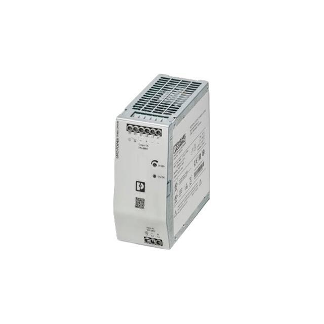
UNO2-PS/1AC/24DC/480W
Power supply unit
Data sheet
107888_en_00
1
© PHOENIX CONTACT 2020-02-14
Description
The UNO POWER power supply features maximum energy
efficiency and can be used anywhere in the world.
Technical data (short form)
Thanks to its high power density, the UNO POWER power
supply unit is the ideal solution, particularly in compact
control boxes.
Input voltage range
100 V AC ... 240 V AC
-15 % ... +10 %
Mains buffering
typ. 17 ms (120 V AC)
typ. 18 ms (230 V AC)
Space-saving
Nominal output voltage (UN)
24 V DC
Setting range of the output voltage
(USet)
24 V DC ... 28 V DC
–
–
–
Particularly compact design
480 W nominal power with an overall width of 59 mm
Alignable without minimum clearance to neighboring
modules
Flexible use
–
–
–
–
Large, wide-range input of the AC supply voltage
Adjustable DC output voltage
Reliable device startup, even at -40°C
Efficiency up to 94.6%
Easy system diagnostics
–
–
Nominal output current (IN)
20 A
Output power (PN)
480 W
Efficiency (for nominal values)
typ. 93 % (120 V AC)
typ. 94.6 % (230 V AC)
Residual ripple
typ. 70 mVPP
MTBF (IEC 61709, SN 29500)
> 900000 h (25 °C)
> 530000 h (40 °C)
> 280000 h (55 °C)
Ambient temperature (operation)
-25 °C ... 70 °C
> 55 °C Derating: 2.5 %/K
Dimensions W/H/D
59 mm / 130 mm / 125 mm
Weight
1 kg
DC OK LED
Floating switch contact
All technical specifications are nominal and refer to a room temperature of 25 °C and 70% relative humidity at
100 m above sea level.
�UNO2-PS/1AC/24DC/480W
2
Table of contents
1
Description ..................................................................................................................................1
2
Table of contents.........................................................................................................................2
3
Ordering data .............................................................................................................................. 4
4
Technical data............................................................................................................................. 5
5
Safety and installation notes...................................................................................................... 12
6
High-voltage test (HIPOT) ......................................................................................................... 13
6.1
6.2
6.3
7
Design ....................................................................................................................................... 14
7.1
7.2
7.3
7.4
8
Rating plate ..................................................................................................................................................14
Device connections and functional elements................................................................................................14
Block diagram...............................................................................................................................................15
Device dimensions .......................................................................................................................................16
Mounting/remove .................................................................................................................................................16
8.1
8.2
8.3
8.4
8.5
8.6
9
High-voltage dielectric test (dielectric strength test) .....................................................................................13
High-voltage dielectric test during the manufacturing process......................................................................13
High-voltage dielectric test performed by the customer ................................................................................13
6.3.1 Performing high-voltage testing.........................................................................................................13
Convection ...................................................................................................................................................16
Mounting position .........................................................................................................................................17
Installation height..........................................................................................................................................17
Keep-out areas .............................................................................................................................................17
Mounting the power supply unit ....................................................................................................................17
Removing the power supply unit...................................................................................................................18
Device connection terminal blocks .................................................................................................................18
9.1
9.2
9.3
9.4
9.5
AC input terminal blocks ...............................................................................................................................18
Protection of the primary side .......................................................................................................................19
9.2.1 Fuse protection in a single-phase supply system ..............................................................................19
9.2.2 Fuse protection in a three-phase supply system ...............................................................................19
Supply system configurations and systems ..................................................................................................19
9.3.1 Connection versions, single-phase supply system ............................................................................19
9.3.2 Connection versions, three-phase supply system .............................................................................19
DC output terminal blocks.............................................................................................................................20
9.4.1 Wiring principle for DC output terminals ............................................................................................20
9.4.2 Protection of the secondary side .......................................................................................................20
Connection terminal blocks, floating switch contact (13/14) .........................................................................20
9.5.1 Wiring principle for the floating switch contact...................................................................................21
10 Function elements ..................................................................................................................... 21
10.1
10.2
10.3
107888_en_00
Operating element – potentiometer UOut .....................................................................................................21
Display element – DC OK LED .....................................................................................................................21
Control element – floating switch contact (13/14) .........................................................................................21
PHOENIX CONTACT
2 / 28
�UNO2-PS/1AC/24DC/480W
11 Output characteristic curves............................................................................................................................. 22
12 Connection versions ........................................................................................................................................... 22
12.1
12.2
12.3
Increasing power .......................................................................................................................................... 22
12.1.1 Series operation................................................................................................................................ 22
12.1.2 Parallel operation .............................................................................................................................. 23
Redundant operation.................................................................................................................................... 23
Fundamental prerequisites for parallel operation (power increase, redundancy operation) ......................... 23
13 Derating .....................................................................................................................................24
13.1
13.2
13.3
Ambient temperature.................................................................................................................................... 24
Installation height ......................................................................................................................................... 24
Position-dependent derating ........................................................................................................................ 25
13.3.1 Normal mounting position ................................................................................................................. 25
13.3.2 Rotated mounting position 90° Z-axis ............................................................................................... 25
13.3.3 Rotated mounting position 180° Z-axis ............................................................................................. 26
13.3.4 Rotated mounting position 270° Z-axis ............................................................................................. 26
13.3.5 Rotated mounting position 90° X-axis ............................................................................................... 27
13.3.6 Rotated mounting position 270° X-axis ............................................................................................. 27
14 Disposal and recycling..............................................................................................................28
107888_en_00
PHOENIX CONTACT
3 / 28
�UNO2-PS/1AC/24DC/480W
3
Ordering data
Description
Type
Order No.
Pcs./Pkt.
Primary-switched UNO power supply for DIN rail
mounting, input: single-phase, output: 24 V DC/480 W
UNO2-PS/1AC/24DC/480W
2910105
1
Accessories
Type
Order No.
Pcs./Pkt.
DIN rail diode module 12-24 V DC/2x20 A or 1x40 A.
Uniform redundancy up to the consumer.
QUINT4-DIODE/12-24DC/
2X20/1X40
2907719
1
Active QUINT redundancy module for DIN rail mounting QUINT-ORING/24DC/2X20/
with ACB (Auto Current Balancing) Technology and
1X40
monitoring functions, input: 24 V DC/2x 20 A, output: 24 V
DC/1 x 40 A, including mounted UTA 107/30 universal DIN
rail adapter
2320186
1
Redundancy module, TRIO POWER, Push-in connection, TRIO2-DIODE/12-24DC/
DIN rail mounting,
2X20/1X40
2907379
1
Pluggable device protection, according to type 3/class III, PLT-SEC-T3-230-FM
for 1-phase power supply networks with separate N and
PE (3-conductor system: L1, N, PE), with integrated
surge-proof fuse and remote indication contact. Also
suitable for DC applications.
2905229
1
Electronic device circuit breaker, number of positions: 1,
mounting type: DIN rail: 35 mm, Color: light grey
RAL 7035
CBMC E4 24DC/1-4A NO
2906031
1
Electronic device circuit breaker, number of positions: 1,
mounting type: DIN rail: 35 mm, Color: light grey
RAL 7035
CBMC E4 24DC/1-10A NO
2906032
1
Electronic device circuit breaker, number of positions: 1,
mounting type: DIN rail: 35 mm, Color: light grey
RAL 7035
CBMC E4 24DC/1-4A+ IOL
2910410
1
Electronic device circuit breaker, number of positions: 1,
mounting type: DIN rail: 35 mm, Color: light grey
RAL 7035
CBMC E4 24DC/1-10A IOL
2910411
1
Electronic device circuit breaker, number of positions: 1,
mounting type: DIN rail: 35 mm, Color: light grey
RAL 7035
CBM E4 24DC/0.5-10A NO-R 2905743
1
Electronic device circuit breaker, number of positions: 1,
mounting type: DIN rail: 35 mm, Color: light grey
RAL 7035
CBM E8 24DC/0.5-10A NO-R 2905744
1
The range of accessories is being continuously extended. The current range of accessories can be found in
the download area for the product.
107888_en_00
PHOENIX CONTACT
4 / 28
�UNO2-PS/1AC/24DC/480W
4
Technical data
Input data
Unless otherwise stated, all data applies for 25°C ambient temperature, 230 V AC input voltage, and nominal
output current (IN).
Input voltage range
100 V AC ... 240 V AC -15 % ... +10 %
Derating
< 90 V AC 1 %/V
Frequency range (fN)
50 Hz ... 60 Hz 10 %
Current draw typ.
5.4 A (100 V AC)
4.4 A (120 V AC)
2.3 A (230 V AC)
2.2 A (240 V AC)
Discharge current to PE
< 3.5 mA
Mains buffering
typ. 17 ms (120 V AC)
typ. 18 ms (230 V AC)
Typical response time
900000 h (25 °C)
> 530000 h (40 °C)
> 280000 h (55 °C)
General data
Degree of protection
IP20
Protection class
I
Inflammability class in acc. with UL 94 (housing / terminal blocks) V0
Side element version
Aluminum
Hood version
Stainless steel
Dimensions W / H / D (state of delivery)
59 mm / 130 mm / 125 mm
Weight
1 kg
Power dissipation
120 V AC
230 V AC
Maximum power dissipation in no-load condition
< 2.9 W
55 °C Derating: 2.5 %/K)
The ambient temperature (operation) refers to IEC 61010 surrounding air temperature.
Ambient temperature (storage/transport)
-40 °C ... 85 °C
Max. permissible relative humidity (operation)
≤ 95 % (at 25 °C, non-condensing)
Installation height
≤ 3000 m (> 2000 m, Derating: 10 %/1000 m)
Vibration (operation)
10 Hz ... 50 Hz, Amplitude ±0.2 mm (according to IEC 60068-2-6)
50 Hz ... 150 Hz, 2,3g, 90 min.
Shock
18 ms, 30g, in each space direction (according to IEC 600682-27)
Degree of pollution
2
Climatic class
3K3 (in acc. with EN 60721)
Overvoltage category
EN 61010-1
EN 62477-1
II (≤ 3000 m)
III (≤3000 m)
Standards
Safety of power supply units up to 1100 V (insulation
distances)
DIN EN 61558-2-16
Electrical safety (of information technology equipment)
IEC 61010-2-201 (SELV)
Electrical safety (of control and regulation devices)
IEC 61010-1
Electronic equipment for use in electrical power
installations
EN 50178/VDE 0160 (PELV)
SELV
IEC 61010-1 (SELV)
IEC 61010-2-201 (PELV)
Safe isolation
IEC 61558-2-16
IEC 61010-2-201
Limitation of mains harmonic currents
EN 61000-3-2
Network version/undervoltage
SEMI F47 - 0706 (185 V AC)
Approvals
UL
SIQ
UL/C-UL Listed UL 61010-1
UL/C-UL Listed UL 61010-2-201
CB-Scheme (IEC 61010-1, IEC 61010-2-201)
Current approvals/permissions for the product can be found in the download area under
phoenixcontact.net/products
107888_en_00
PHOENIX CONTACT
9 / 28
�UNO2-PS/1AC/24DC/480W
Electromagnetic compatibility
Conformance with EMC Directive 2014/30/EU
Noise emission according to EN 61000-6-3 (residential and commercial) and EN 61000-6-4 (industrial)
CE basic standard
Minimum normative
requirements
Higher requirements
in practice (covered)
Conducted noise emission EN 55016
EN 61000-6-4 (Class A)
EN 61000-6-3 (Class B)
Noise emission EN 55016
EN 61000-6-4 (Class A)
EN 61000-6-3 (Class B)
EN 61000-3-2
EN 61000-3-2 (Class A)
Minimum normative requirements of EN 61000-6-2 (CE)
(immunity for industrial environments)
Higher requirements
in practice (covered)
Harmonic currents EN 61000-3-2
EN 61000-6-2:2005
CE basic standard
Electrostatic discharge EN 61000-4-2
Housing contact discharge
4 kV (Test Level 2)
6 kV (Test Level 3)
Housing air discharge
8 kV (Test Level 3)
8 kV (Test Level 3)
Criterion B
Criterion A
Comments
Electromagnetic HF field EN 61000-4-3
Frequency range
80 MHz ... 1 GHz
80 MHz ... 1 GHz
Test field strength
10 V/m (Test Level 3)
10 V/m (Test Level 3)
Frequency range
1.4 GHz ... 2 GHz
1 GHz ... 2 GHz
Test field strength
3 V/m (Test Level 2)
10 V/m (Test Level 3)
Frequency range
2 GHz ... 2.7 GHz
2 GHz ... 3 GHz
Test field strength
1 V/m (Test Level 1)
10 V/m (Test Level 3)
Criterion A
Criterion A
Comments
Fast transients (burst) EN 61000-4-4
Input 2 kV (Test Level 3 - asymmetrical) 4 kV (Test Level 4 - asymmetrical)
Output 2 kV (Test Level 3 - asymmetrical) 2 kV (Test Level 3 - asymmetrical)
Comments
Criterion B
Criterion A
Surge voltage load (surge) EN 61000-4-5
Input
Output
Comments
1 kV (Test Level 2 - symmetrical) 2 kV (Test Level 3 - symmetrical)
2 kV (Test Level 3 - asymmetrical) 4 kV (Test Level 4 - asymmetrical)
0.5 kV (Test Level 1 symmetrical)
0.5 kV (Test Level 1 asymmetrical)
1 kV (Test Level 2 - symmetrical)
2 kV (Test Level 3 - asymmetrical)
Criterion B
Criterion A
Conducted interference EN 61000-4-6
Input/output
Frequency range
Voltage
Comments
107888_en_00
asymmetrical
asymmetrical
0.15 MHz ... 80 MHz
0.15 MHz ... 80 MHz
10 V (Test Level 3)
10 V (Test Level 3)
Criterion A
Criterion A
PHOENIX CONTACT
10 / 28
�UNO2-PS/1AC/24DC/480W
EN 61000-6-2:2005
CE basic standard
Minimum normative requirements of EN 61000-6-2 (CE)
(immunity for industrial environments)
Higher requirements
in practice (covered)
70 % , 25 periods (Test Level 2)
70 % , 25 / 30 periods (Test Level 2)
Voltage dips EN 61000-4-11
Input voltage (230 V AC , 50 Hz)
Voltage dip
Comments
Criterion A
Criterion A
Voltage dip
40 % , 10 periods (Test Level 2)
40 % , 12 periods (Test Level 2)
Comments
Criterion A
Criterion A
Voltage dip
0 % , 1 period (Test Level 2)
0 % , 1 period (Test Level 2)
Comments
Criterion B
Criterion B
Key
Criterion A
Normal operating behavior within the specified limits.
Criterion B
Temporary impairment to operational behavior that is corrected by the device itself.
107888_en_00
PHOENIX CONTACT
11 / 28
�UNO2-PS/1AC/24DC/480W
5
Safety and installation notes
Safety notes and warning instructions
Symbols used
WARNING: Danger to life by electric
shock!
Instructions and possible hazards are indicated by
corresponding symbols in this document.
–
This is the safety alert symbol. It is used to
alert you to potential personal injury hazards.
Obey all safety measures that follow this
symbol to avoid possible personal injuries.
There are different categories of personal injury that are
indicated by a signal word.
–
–
–
Only skilled persons may install, start up, and operate
the device.
Never carry out work when voltage is present.
Establish connection correctly and ensure protection
against electric shock.
Cover termination area after installation in order to avoid
accidental contact with live parts (e. g., installation in
control cabinet).
WARNING
NOTE
This indicates a hazardous situation which, if
not avoided, could result in death or serious
injury.
–
CAUTION
This indicates a hazardous situation which, if
not avoided, could result in minor or moderate
injury.
The following symbols are used to indicate potential
damage, malfunctions, or more detailed sources of
information.
–
–
–
–
–
NOTE
This symbol together with the signal word
NOTE and the accompanying text alert the
reader to a situation which may cause
damage or malfunction to the device,
hardware/software, or surrounding property.
–
This symbol and the accompanying text
provide the reader with additional information
or refer to detailed sources of information.
–
–
–
–
–
–
–
107888_en_00
Observe the national safety and accident prevention
regulations.
Assembly and electrical installation must correspond to
the state of the art.
The power supply is a built-in device and is designed for
mounting in a control cabinet.
The IP20 degree of protection of the device is intended
for use in a clean and dry environment.
Observe mechanical and thermal limits.
Horizontal mounting position (normal mounting
position)
Mount the power supply unit in the standard installation
position. Position of the L/N connection terminal blocks
at bottom.
Ensure that the primary-side wiring and secondary-side
wiring are the correct size and have sufficient fuse
protection.
For the connection parameters for wiring the power
supply, such as the required stripping length with and
without ferrule, refer to the technical data section.
Use copper cables for operating temperatures of
75 °C (ambient temperature 55 °C)
90 °C (ambient temperature 75 °C).
The power supply is approved for the connection to TN,
TT and IT power grids (star networks) with a maximum
phase-to-phase voltage of 240 V AC
Protect the device against foreign bodies penetrating it,
e.g., paper clips or metal parts.
The power supply is maintenance-free. Repairs may
only be carried out by the manufacturer. The warranty
no longer applies if the housing is opened.
The power supply may only be used for its intended use.
PHOENIX CONTACT
12 / 28
�UNO2-PS/1AC/24DC/480W
6
High-voltage test (HIPOT)
This protection class I power supply is subject to the Low
Voltage Directive and is factory tested. During the HIPOT
test (high-voltage test), the insulation between the input
circuit and output circuit is tested for the prescribed electric
strength values, for example. The test voltage in the highvoltage range is applied at the input and output terminal
blocks of the power supply. The operating voltage used in
normal operation is a lot lower than the test voltage used.
High-voltage tests can be performed as
described.
6.3.1
Performing high-voltage testing
If high-voltage testing of the control cabinet or the power
supply as a stand-alone component is planned during final
inspection and testing, the following features must be
observed.
– The power supply wiring must be implemented as
shown in the wiring diagram.
– The maximum permissible test voltages must not be
exceeded.
Avoid unnecessary loading or damage to the power supply
due to excessive test voltages.
For the relevant applicable test voltages and
insulation distances, refer to the
corresponding table (see technical data:
electric strength of the insulation section).
The test voltage should rise and fall in ramp
form. The relevant rise and fall time of the
ramp should be at least two seconds.
6.1
High-voltage dielectric test (dielectric strength
test)
3
UNO2 POWER Ord.No. 2910105
In order to protect the user, power supplies (as electric
components with a direct connection to potentially
hazardous voltages) are subject to more stringent safety
requirements. For this reason, permanent safe electrical
isolation between the hazardous input voltage and the
touch-proof output voltage as safety extra-low voltage
(SELV) must always be ensured.
3.1
3.2
13
14
2.1
2.2
+
+
2.3
2.4
Output DC
24V 480W
24-28 V
DC OK
2
HV
In order to ensure permanent safe isolation of the AC input
circuit and DC output circuit, high-voltage testing is
performed as part of the safety approval process (type test)
and manufacturing (routine test).
�/=
Input AC
100-240V
6.2
High-voltage dielectric test during the
manufacturing process
During the power supply manufacturing process, a highvoltage test is performed as part of the dielectric test in
accordance with the specifications of IEC/UL/EN 61010-1.
The high-voltage test is performed with a test voltage of at
least 2.2 kV AC or higher. Routine manufacturing tests are
inspected regularly by a certification authority.
6.3
High-voltage dielectric test performed by the
customer
Apart from routine and type tests to guarantee electrical
safety, the end user does not have to perform another highvoltage test on the power supply as an individual
component. According to EN 60204-1 (Safety of machinery
- Electrical equipment of machines) the power supply can be
disconnected during the high-voltage test and only installed
once the high-voltage test has been completed.
107888_en_00
1.1
L
1.2
N
1.3
1
Figure 1
Potential-related wiring for the high-voltage
test
Key
No. Designation
1
2
3
Color coding
AC input circuit Red
High-voltage
-tester
DC output circuit Blue
Potential levels
Potential 1
-Potential 2
PHOENIX CONTACT
13 / 28
�UNO2-PS/1AC/24DC/480W
7
Design
7.2
7.1
Rating plate
Device connections are labeled with connection tags to
ensure clear and definitive identification.
In accordance with ProdSG, every device must therefore be
fitted with a rating plate. All relevant information on the safe
use of the device must also be included.
The connection tags are split into the following connection
levels:
Connection
level
1.x
2.x
3.x
The power supply device rating plate is
located on the right-hand side of the housing
(as viewed from the front).
1
Description
Input
Output
Signal
UNO POWER Ord.No. 2910105
In accordance with the German Product Safety Law
(ProdSG) it is only permissible to make such products
available on the market if they meet certain safety
standards. It must be ensured at all times that users are not
exposed to hazards.
Device connections and functional elements
3.1
3.2
13
14
2.1
2.2
+
+
2.3
2.4
2
Output DC
24V 480W
24-28 V
3
DC OK
PHOENIX CONTACT GmbH & Co. KG
Flachsmarktstraße 8
32825 Blomberg, Germany
Type
Order No.:
7
4
1
2
5
Input:
Input AC
100-240V
1.1
6
6
N
1.3
7
Figure 3
xxxxxxxXXYYWWTZZZZ
5
L
1.2
3
Output:
Read manual No. xxxxxxx before connecting to mains
Lire manuel No. xxxxxxx avant de raccorder au réseau
www.phoenixcontact.com
Made in Thailand
4
Location of functional elements and device
connections
Key
No. Designation
Figure 2
Rating plate information
1
Key
2
No.
1
2
3
4
5
6
7
107888_en_00
Designation
Identification of the provider
Product designation
Ambient conditions
Bar code and serial number for device identification
Designation of product-related device documentation
Device approvals
Device connection data
3
4
5
6
7
Connection terminal blocks, floating
switch contact (13/14), contact load
max. 30 V AC/DC, 100 mA
Connection terminal block output
voltage: Output DC +/Potentiometer output voltage
Signaling DC OK LED
Snap-on foot for DIN rail mounting
QR code web link
Connection terminal block input voltage: Input /L/N
Connection
labeling
3.1, 3.2
2.1 ... 2.4
----1.1 ... 1.3
PHOENIX CONTACT
14 / 28
�UNO2-PS/1AC/24DC/480W
7.3
Block diagram
Input AC
1.1
L
1.2
N
1.3
Output DC
2.1
Filter
aktive
PFC
Filter
+
2.3
2.4
Signal
Functions
UVP
2.2
OVP
Figure 4
3.1
13
3.2
14
User Interface
OTP
OCP
SCP
UOUT
DC OK
Block diagram
Key
Symbol
Designation – Input AC, Output DC
Input fuse, internal device protection
Symbol
UVP
EMC filter
Filter
OVP
Rectification
aktive
PFC
Power factor correction (PFC)
OTP
Switching transistor
OCP
Transmitter with electrical isolation
SCP
Designation – Functions
Undervoltage protection protects the AC
input of the power supply against damage in
the event of an AC undervoltage.
Overvoltage protection protects the DC output of the power supply and the connected
load against damage in the event of an overvoltage
Overtemperature protection protects the
power supply against damage in the event of
impermissibly high intrinsic external heating.
Overcurrent protection protects the DC output of the power supply against damage in
the event of an impermissibly high current
load.
Short-circuit protection protects the DC output of the power supply against damage in
the vent of an output-side short circuit.
Smoothing capacitor
Symbol
Designation – Signal
Floating switch contact (13/14) for forwarding
the operational readiness to a superordinate
control system.
Symbol
Designation – User interface
Potentiometer for setting the output voltage
UOut
UOUT
DC OK LED, indicates the operating status of
the power supply
DC OK
107888_en_00
PHOENIX CONTACT
15 / 28
�UNO2-PS/1AC/24DC/480W
7.4
Device dimensions
8
The fanless convection-cooled power supply can be
snapped onto 35 mm DIN rails with a top hat profile (TH 357.5 / TH 35-15) in accordance with EN 60715.
UNO2 POWER Ord.No. 2910105
59
3.1
3.2
13
14
Mounting/remove
2.1
2.2
+
+
2.3
2.4
8.1
Convection
Output DC
24V 480W
24-28 V
130
DC OK
To ensure sufficient convection, a minimum clearance is
necessary between the power supply and above/below the
installed devices. The minimum clearances are rated based
on the standard mounting position with nominal power
supply operation (see section: Restricted areas).
Input AC
100-240V
Figure 5
L
1.2
N
1.3
UNO2 POWER Ord.No
. 2910105
1.1
Device dimensions (dimensions in mm)
3.1
13
3.2
14
2.1
+
Ou
tp
24 ut D
V4 C
80
W
2.2
+
2.3
-
2.4
-
130
24
-28
125
DC
O
V
K
INP
U
100 T AC
-24
0
L V
1.2 N
1.3
80
130
1.1
Schematic diagram of the convection cooling
48
Figure 7
Figure 6
107888_en_00
Device dimensions (dimensions in mm)
PHOENIX CONTACT
16 / 28
�UNO2-PS/1AC/24DC/480W
Mounting position
8.4
Keep-out areas
The specified technical data for the power supply is based
on nominal operation in the standard mounting position. Any
different technical data based on deviating mounting
positions or other ambient conditions is labeled accordingly
(see section: Derating).
30
59
3.1
3.2
13
14
2.1
2.2
+
+
2.3
2.4
Output DC
24V 480W
24-28 V
DC OK
190
UNO2 POWER Ord.No
. 2910105
95
UNO POWER Ord.No. 2910105
8.2
3.1
13
3.2
14
2.1
+
Ou
tp
24 ut D
V4 C
80
W
2.2
+
2.3
-
2.4
-
Input AC
100-240V
24
-28
V
1.1
L
1.2
N
1.3
DC
OK
INP
U
100 T AC
-24
0
L V
1.2 N
1.3
1.1
Figure 8
8.3
Power supply installed in the normal mounting
position
Installation height
You can operate the power supply without power limitations
up to an installation altitude of 2000 m. For altitudes higher
than 2000 m, different specifications apply due to the
differing air pressure and the reduced convection cooling
associated with this (see section: Derating).
Figure 9
8.5
Device dimensions and minimum keep-out
areas (in mm)
Mounting the power supply unit
Proceed as follows to mount the power supply:
1. In the standard mounting position, the power supply is
mounted on the DIN rail from above. When doing so,
ensure that the snap-on foot engages correctly behind
the DIN rail (A).
2. Then press the power supply down until the snap-on
foot audibly latches into place (B).
3. Check that the power supply is securely attached to the
DIN rail.
A
Click
B
Figure 10
107888_en_00
Snapping the power supply onto the DIN rail
PHOENIX CONTACT
17 / 28
�UNO2-PS/1AC/24DC/480W
8.6
Removing the power supply unit
9
Proceed as follows to remove the power supply:
1. Take a suitable screwdriver and insert this into the latch
opening on the snap-on foot (A).
2. Release the lock by lifting the screwdriver (B).
3. Carefully swivel the power supply forward (C) so that
the lock slides back into the starting position.
4. Then separate the power supply from the DIN rail (D).
D
Device connection terminal blocks
The AC input, DC output, and signal terminal blocks on the
front of the power supply feature screw connection
technology.
For the necessary connection parameters for
the connection terminal blocks, refer to the
technical data section.
9.1
AC input terminal blocks
The power supply is designed such that it can be operated
on single-phase AC supply systems or on two phase
conductors of three-phase systems. Here, the star supply
system supports various supply system configurations,
for example TT, TN, and IT systems.
C
A
Figure 11
The power supply is connected on the primary side via the
Input AC connection terminal blocks (connection level 1.x,
input).
B
The power supply is approved for connection
to TN, TT, and IT power grids with a maximum
phase-to-phase voltage of 240 V AC.
Removing the power supply from the DIN rail
3.1
13
3.2
14
2.1
+
Ou
tp
24 ut D
V4 C
80
W
2.2
+
2.3
-
2.4
-
24
-28
DC
O
V
K
INP
U
100 T AC
-24
0
L V
1.1 N
1.1
1.1
Figure 12
107888_en_00
Position of the AC input terminal blocks
PHOENIX CONTACT
18 / 28
�UNO2-PS/1AC/24DC/480W
9.2
Protection of the primary side
The installation of the power supply must conform to the
regulations of EN 61010. It must be possible to switch the
power supply off using a suitable disconnection device
outside of the power supply. The line protection on the
primary side is suitable for this (see section: Technical data).
9.2.1
Fuse protection in a single-phase supply
system
9.3
Supply system configurations and systems
9.3.1
Connection versions, single-phase supply
system
The power supply is designed such that it can also be
operated on two phase conductors of three-phase systems.
TT / TN / IT (PE)
TN-C
Input AC
Input AC
L
1.1
1.2
N
1.3
1.1
L
1.2
N
1.3
Input AC
1.1
L
1.2
N
1.3
L1
L2
L3
N
PE
L1
L2
L3
Schematic diagram, single-phase fuse
protection
N
PE
PEN
Figure 15
Figure 13
9.2.2
L1
L2
L3
N
PE
9.3.2
Wiring principle in a star supply system, singlephase operation
Connection versions, three-phase supply
system
DANGER: Hazardous voltage
Fuse protection in a three-phase supply system
When operating the power supply on a threephase system, observe the maximum
permissible phase-to-phase voltage (see
section: Technical data).
DANGER: Hazardous voltage
The primary-side fuse protection in two-phase
operation must be cover all poles.
Input AC
TT / TN / IT (PE)
TN-C
L
Input AC
Input AC
1.1
1.2
N
1.3
1.1
L1
L2
L3
N
PE
L1
L2
L3
N
PE
Figure 14
107888_en_00
Schematic diagram, two-phase fuse protection
Figure 16
L
1.2
N
1.3
1.1
L1
L2
L3
PEN
L
1.2
N
1.3
N
PE
Wiring principle in a star supply system, twophase operation
PHOENIX CONTACT
19 / 28
�UNO2-PS/1AC/24DC/480W
9.4
DC output terminal blocks
Connect the DC load to be supplied to the Output DC
connection terminal blocks (connection level 2.x, output). By
default, the power supply is preset to a nominal output
voltage of 24 V DC. To compensate for a line-related
voltage drop over long distances between the power supply
and the DC load, you can adjust the DC output voltage using
the potentiometer (see section: Potentiometer).
9.4.2
Protection of the secondary side
The power supply is electronically short-circuit-proof and
no-load-proof. In the event of an error, the output voltage is
limited
If sufficiently long connecting cables are used,
fuse protection does not have to be provided
for each individual load.
9.5
Connection terminal blocks, floating switch
contact (13/14)
There is a floating switch contact on the Output DC
connection terminal blocks (connection level 3.x, signal) for
forwarding to a superordinate control system.
NOTE: Damage due to impermissibly high
contact load
3.1
3.2
13
14
2.1
+
Ou
tp
24 ut D
V4 C
80
W
2.2
+
Observe the contact connection data: Max.
30 V AC/DC, 100 mA
2.3
2.4
-
24
DC
-28
V
OK
INP
U
100 T AC
-24
0
L V
1.1 N
1.1
1.1
Figure 17
9.4.1
Position of DC output terminals
3.1
13
3.2
14
2.1
+
Ou
tp
24 ut D
V4 C
80
W
Wiring principle for DC output terminals
2.2
+
The power supply has two separate connection terminal
blocks with positive and negative potentials for supplying
DC loads. Connect the DC loads to be supplied to these
connection terminal blocks.
2.3
2.4
-
24
DC
R
Load
-28
V
OK
INP
U
100 T AC
-24
0
L V
1.1 N
1.1
1.1
3.1
13
3.2
2.1
2.2
14
+
+
2.3
2.4
Output DC
24V 480W
Figure 18
107888_en_00
Figure 19
Position of the connection terminal blocks,
floating switch contact
Wiring principle for DC output terminal blocks
PHOENIX CONTACT
20 / 28
�UNO2-PS/1AC/24DC/480W
9.5.1
Wiring principle for the floating switch contact
max. 30 V AC/DC
100 mA
PLC
Digital Input
3.1 3.2
x DI
13
GND
14
Figure 20
10
Wiring principle, floating switch contact for
forwarding to a superordinate control system
Function elements
The functional elements of the power supply, with the
exception of the floating switch contact, are situated on the
front of the housing of the power supply and are categorized
as follows:
– Operating element
– Display element
– Control element
10.1
10.2
A DC OK LED is available for preventive function monitoring
of the power supply. Through various different signals, the
DC OK LED provides information on the operating status of
the power supply.
The possible DC OK statuses are to be found in the
following table:
A DC OK LED is available for preventive function monitoring
of the power supply. Through various different signals, the
DC OK LED provides information on the operating status of
the power supply.
DC OK LED
NOTE: Damage possible, beware of the
potentiometer setting range end stops
The potentiometer setting range is limited via
end stops. Accidentally over-torqueing the
end stops can damage the potentiometer.
24-28 V
Figure 21
107888_en_00
Potentiometer
Description
Primary-side AC supply is not available
or too low.
Power supply in normal operation UOUT
>0.9 x UN (UN = 24 V DC)
Power supply in Overload operation
UOUT 55°C Derating: 2.5%/K
62.5%
-25
55
70
TA [°C]
Figure 27
107888_en_00
Output power depending on the ambient
temperature
PHOENIX CONTACT
24 / 28
�UNO2-PS/1AC/24DC/480W
13.3
Position-dependent derating
In order that you can use the nominal power of the power supply without limitation, the power supply should always be
mounted in the standard mounting position. Sufficient device-side convection is always assured if the power supply is
mounted in the standard mounting position and the necessary restricted areas are observed.
NOTE: Damage due to thermal overload
If the supply is mounted in a different mounting position, only a reduced amount of power can be drawn.
Otherwise, the power supply will be thermally loaded disproportionately and the device service life significantly
reduced.
UNO2 POWER Ord.No
. 2910105
[A]
13.3.1 Normal mounting position
IN
3.1
13
3.2
14
2.1
+
Ou
tp
24 ut D
V4 C
80
W
2.2
+
100%
62,5%
2.3
2.4
-
24
DC
-28
V
OK
-25
55
Y
[°C]
INP
U
100 T AC
-24
0
L V
1.2 N
1.3
Z
70
1.1
X
[A]
13.3.2 Rotated mounting position 90° Z-axis
IN
100%
1.1
O2
L
INPUT AC
100-240V
1.1
UN
12,5%
RO
N
1.1
PO
WE
rd.N
o. 2
9
14
05
-25
35
70
3.2
2.1
+
2.2
+
[°C]
2.3
-
24-28V
2.4
-
Z
3.1
13
Output DC
24V 480W
DC OK
Y
101
X
107888_en_00
PHOENIX CONTACT
25 / 28
�UNO2-PS/1AC/24DC/480W
[A]
13.3.3 Rotated mounting position 180° Z-axis
IN
100%
N
1.3
L
1.2
1.1
V
40
0-2
10
tA
C
Inp
u
25%
DC
OK
24
-28
V
-25
24 ut
V 48 D
0W C
Ou
+
14
13
70
[°C]
tp
+
2.4
2.3
2.2
2.1
3.2
0105
X
3.1
Z
40
2911
ER Ord.No.
UNO2 POW
Y
[A]
13.3.4 Rotated mounting position 270° Z-axis
IN
24-28 V
DC OK
+
2.2
+
2.1
24V 480W
14
N
1.3
L
1.2
Input AC
-25
30
70
1.1
100-240V
13
U
N
O
2
PO
W
O
rd
.N
o.
29
11
01
05
Y
ER
3.1 3.2
Output DC
2.3
2.4
100%
[°C]
Z
X
107888_en_00
PHOENIX CONTACT
26 / 28
�UNO2-PS/1AC/24DC/480W
13.3.5 Rotated mounting position 90° X-axis
05
1101
WE
RO
o.
rd.N
29
13
14
2.1
2.2
+
2.3
+
2.4
-
[A]
PO
3.2
O2
3.1
UN
-
8
-2
24
IN
V
D
C
O
100%
K
In
1.1
10
1.2
pu
0-2
L
tA
40
V
1.3
C
N
25%
-25
Y
40
70
[°C]
Z
X
[A]
13.3.6 Rotated mounting position 270° X-axis
IN
100%
12,5%
-25
Y
Z
35
70
[°C]
X
107888_en_00
PHOENIX CONTACT
27 / 28
�UNO2-PS/1AC/24DC/480W
14
Disposal and recycling
Ensure the correct disposal of electronic components
Do not dispose of the power supply as household waste.
Observe the applicable national standards and regulations.
Ensure correct disposal or recycling
Dispose of or recycle packaging material that is no longer needed as household waste.
Observe the applicable national standards and regulations.
107888_en_00
PHOENIX CONTACT GmbH & Co. KG • Flachsmarktstraße 8 • 32825 Blomberg • Germany
phoenixcontact.com
28 / 28
�