EMM W 3/5-500
Electronic Motor Management
Data Sheet
01/2005
Features
EMM provides all the advantages of modern active
power monitoring. The active-power input of a drive
system or another 3-phase load is calculated every
6.6 ms from three currents, voltages, and the phase
angle.
Currents greater than 5 A are led to the module via
transformers. The load is switched by a separate
switching element. In this way, the EMM reliably
protects connected loads – regardless of their current
consumption – against overload and underload and
provides continuous status monitoring.
Switching thresholds, signaling thresholds, and four
configurable confirmation outputs provide motor and
system protection.
All relevant values can be viewed via the integrated
display of the configuration software or a fieldbus
interface:
– Apparent power, active power, and reactive
power
– Currents and voltages
– Phase angle
– Operating cycle counter and elapsed-hour meter
– Power meter
The integrated memory can be used to record
complete curves, which can be used, for example, in
the system documentation.
Actuators and variable-speed drives, pumps, etc. are
connected using the right rotation, left rotation,
reverse, and limit switch modes (with integrated
restart inhibit) and at the same time are monitored and
protected against dirt or wear.
Technical Data
Input Data
Module supply UN
Maximum current consumption
Control voltage right/left
Current consumption right/left
Switching output supply
Input current
Input wiring
5156360_01_en
24 V DC ±20%
80 mA
24 V DC ±20%
7 mA
24 V DC ±20%
2A
LED, diode for protection against polarity reversal,
surge protection
1
�EMM W 3/5-500
Power Measurement
Voltage input V1, V2, V3
Nominal current at 550 V AC
Input wiring
Current measuring input L1/T1, L2/T2, L3/T3
Maximum cable length between the transformer and
EMM
110 V AC - 575 V AC, 50/60 Hz
6 mA
RCV circuit
5 A AC, maximum
5 m (16.40 ft.) at 2.5 mm2(14 AWG)/3 m (9.84 ft.) at
1.5 mm2 (16 AWG)
Output Data
Confirmation outputs O1, O2, O3, O4 with 1 signal
Switching output OL, OR with 1 signal
UN - 1 V/50 mA, maximum
UN/2 A
Free-wheeling diode, surge protection, protected
against short circuits and overloads
General Data
Housing dimensions (length x width x height)
Insulating housing version
Test voltage I/O
Ambient operating temperature range
Standards/specifications
Safe isolation input/output
Degree of protection according to
IEC 60529/EN 60529/DIN VDE 0470-1
Mounting position
Mounting
2
107 mm x 62 mm x 120 mm (4.213 x 2.441 x 4.724 in.)
Polycarbonate (PC), color: green
2.5 kVrms
-20°C to +60°C (-4°F to +140°F)
EN 61000-4-2/DIN EN 61000-4-2/VDE 0847-4-2;
EN 61000-4-3/DIN EN 61000-4-3/VDE 0847-4-3;
EN 61000-4-4/DIN EN 61000-4-4/VDE 0847-4-4;
EN 61000-4-5/DIN EN 61000-4-5/VDE 0847-4-5;
EN 61000-4-6/DIN EN 61000-4-6/VDE 0847-4-6;
IEC 60664/IEC 60664 A/DIN VDE 0110
DIN EN 50178 (VDE 0160)
IP20
Vertical (DIN rail horizontal)
Can be mounted with spacing ≥ 20 mm (0.787 in.)
5156360_01_en
�EMM W 3/5-500
Connection Data
Figure 1
Connection data
The following cable cross sections can be connected:
Solid
[mm2]
0.2 - 6
Stranded
[mm2]
0.2 -4
AWG
25 - 10
Stripping
Length L [mm]
8 mm (0.31 in.)
Block Diagram
Parameterization
24 V DC
Logic
µP
Confirmation
24 V DC
Memory
24 V DC
V.24
Alarm
(RS-232)
Power calculation
24 V DC
Switching output
Figure 2
5156360_01_en
Block diagram
3
�EMM W 3/5-500
Connection Versions
Switching Element
Depending on the application, an electromechanical contactor or a contactor-type reversing starter
combination, or an electronic load relay or a reversing-load relay should be used to actually switch
the load.
Confirmation
outputs
Left rotation
Right rotation
Module
supply
The EMM has two switching outputs with 24 V DC/2 A to control these switching elements.
Voltage
Current
measurement measurement
Control
EMM W 3/5-500
2 A switching
output
Current
measurement
Supply
V.24
(RS-232)
Left rotation
Separate switching element
Right rotation
GND
Figure 3
4
Connection version 1: Conductor currents < 5 A, without external current transformers
5156360_01_en
�EMM W 3/5-500
Current Transformer
Separate current transformers should be used for currents greater than 5 A. Transformers with a
secondary nominal current of 5 A should be selected.
Confirmation
outputs
Left rotation
Right rotation
Module
supply
The primary nominal current is determined by the current consumption of the device (see Figure 4).
Control
Voltage
measurement
Current
measurement
EMM W 3/5-500
Current
measurement
2 A switching output
Supply
V.24
(RS-232)
Left rotation
Separate switching element
Right rotation
GND
Figure 4
5156360_01_en
Connection version 2: Conductor currents > 5 A, with external current transformers
5
�EMM W 3/5-500
Ordering Data
Description
Order Designation
Order No.
Electronic motor management
EMM W 3/5-500
29 63 55 6
For marking systems and assembly material, see CLIPLINE catalog.
© PHOENIX CONTACT 01/2005 Technical modifications reserved
Make sure you always use the latest documentation.
It can be downloaded from www.download.phoenixcontact.com.
PHOENIX CONTACT GmbH & Co. KG
Flachsmarktstr. 8
32825 Blomberg
Germany
+49 - 52 35 - 30 0
+49 - 52 35 - 34 12 00
www.phoenixcontact.com
Worldwide Locations:
www.phoenixcontact.com/salesnetwork
6
5156360_01_en
�
很抱歉,暂时无法提供与“2963556”相匹配的价格&库存,您可以联系我们找货
免费人工找货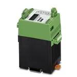


 工商网监
湘ICP备2023018690号
工商网监
湘ICP备2023018690号
