ELR W 3/9-400
ELR W 3/9-500
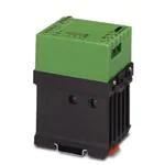
Electronic Reversing-Load Relay
for 3-Phase Networks
Data Sheet
01/2005
Features
Electronic Reversing-Load Relay
ELR W 3/9...
ELR W 3/9... electronic reversing-load relays are the
practical and user-friendly further development of
electronic load relays for 3-phase networks.
The ELR W 3/9... is the fully electronic alternative to
mechanical contactors. It features a compact design
and low control power. A further advantage is the highquality, safe screw connection technology.
These components feature high switching
frequencies, virtually unlimited service life, no spark
interference, and completely silent switching at zero
voltage crossing. The compact, DIN rail-mountable
modules meet all the requirements of an electronic
reversing contactor circuit that has been designed
specifically for industrial applications. Both the
interlocking of control inputs and the complete wiring
of the load contacts are incorporated in the device.
Costly locking switches and contact wiring are thus a
thing of the past.
In accordance with DIN VDE 0110 and
DIN VDE 0636, a conductor cross section
of 1.5 mm2 (16 AWG), which must be
fitted with one fuse each (10 A slow-blow
as mains protection), is required to
connect the electronic load relay to the
3-phase network.
Cabling has been reduced to an absolute minimum.
Only the following must be applied:
– Control voltage, supply voltage
input and output
– 3-phase load
The status is clearly indicated by separate LEDs for
"right rotation", "left rotation", "operating voltage" or
"impermissible control".
A short circuit between two phases at the moment of
switching is prevented by the integrated delay
between the control pulse and the load control.
RCV protective circuits on the output side reduce
voltage peaks that occur in the load circuit to a safe
level and prevent damage to the output electronics.
5104778_03_en
1
�ELR W 3/9-400/ELR W 3/9-500
Technical Data
Input Data (Input)
Operating voltage UB
Maximum current consumption
Control voltage right/left
Input current right/left
Right rotation/left rotation switchover time
(switch-on time)
Input wiring
1
ELR W 3/9-400
ELR W 3/9-500
24 V DC +25%; -20%1
40 mA
24 V DC +25%; -20%1
6 mA, approximately
20 ms
LED, diode for protection against polarity reversal,
surge protection
The operating voltage and control voltage inputs must be operated with power supply
modules according to DIN 19240 (maximum 5% residual ripple). To prevent the inductive
or capacitive coupling of disturbing pulses in long control cables, we recommend the use
of shielded cables.
Output Data (Output)
Operating voltage (conductor voltage)
50 Hz/60 Hz
Operating voltage range
Reverse voltage
Maximum continuous load current
Load current depending on the ambient operating
temperature
ELR W 3/9-400
400 V AC
ELR W 3/9-500
500 V AC
110 V AC - 440 V AC
110 V AC - 550 V AC
1000 V
1200 V
3x9A
Load current [A]
Operating time: 100% operating factor
Ambient operating temperature [°C]
Figure 1
2
Load current depending on the ambient
operating temperature
5104778_03_en
�ELR W 3/9-400/ELR W 3/9-500
Output Data (Output) (Continued)
Power dissipation depending on the load current
ELR W 3/9-400
ELR W 3/9-500
Power dissipation [W]
Operating time: 100% operating factor
Surge current
Minimum load current
Residual voltage at IN
Residual current in the OFF state
Reversing frequency right rotation/left rotation
(cos ϕ = 0.5)
Output wiring
General Data
Housing dimensions (length x width x height)
Insulating housing version
Test voltage I/O
Ambient operating temperature range
Standards/specifications
Degree of protection according to
IEC 60529/EN 60529/DIN VDE 0470-1
Mounting position
Mounting
5104778_03_en
1.5
4.5
7.5
Current per phase [A]
Figure 2
Power dissipation depending on the
load current
230 A (t = 10 ms)
150 mA
1.7 V, typical
6 mA, typical
10 Hz, maximum
RCV circuit, red LED (error message)
84 mm x 62 mm x 110 mm (3.307 x 2.441 x 4.331 in.)
Polycarbonate (PC), color: green
2.5 kVrms
-20°C to +60°C (-4°F to +140°F)
EN 61000-4-4/DIN EN 61000-4-4/VDE 0847-4-4;
EN 61000-4-5/DIN EN 61000-4-5/VDE 0847-4-5;
IEC 60664/IEC 60664 A/DIN VDE 0110, basic
insulation
IP20
Vertical (DIN rail horizontal)
Can be mounted with spacing ≥ 20 mm (0.787 in.)
3
�ELR W 3/9-400/ELR W 3/9-500
Connection Data
Figure 3
Connection data
The following cable cross sections can be connected:
Solid
[mm2]
0.2 - 6
Stranded
[mm2]
0.2 - 4
AWG
Stripping
Length L [mm]
25 - 10 8 mm (0.31 in.)
Block diagram
24 V
"left"
24 V
"right"
Alarm
Figure 4
4
Block diagram
5104778_03_en
�ELR W 3/9-400/ELR W 3/9-500
Ordering Data
Description
Order Designation
Order No.
Electronic reversing-load relay
for directly controlling devices in a
3-phase network,
with LED and protective circuit.
ELR W 3/9-400
29 64 17 3
ELR W 3/9-500
29 64 18 6
For marking systems and assembly material, see CLIPLINE catalog.
© PHOENIX CONTACT 01/2005 Technical modifications reserved
Make sure you always use the latest documentation.
It can be downloaded from www.download.phoenixcontact.com.
PHOENIX CONTACT GmbH & Co. KG
Flachsmarktstr. 8
32825 Blomberg
Germany
+49 - 52 35 - 30 0
+49 - 52 35 - 34 12 00
www.phoenixcontact.com
Worldwide Locations:
www.phoenixcontact.com/salesnetwork
5
5104778_03_en
�
很抱歉,暂时无法提供与“2964186”相匹配的价格&库存,您可以联系我们找货
免费人工找货- 国内价格 香港价格
- 1+7966.458131+996.74767


 工商网监
湘ICP备2023018690号
工商网监
湘ICP备2023018690号

