OT 3M, OT 4M, OT 6M
Operator terminals with FSTN display
AUTOMATION
Data sheet
7312_en_04
1
© PHOENIX CONTACT - 08/2008
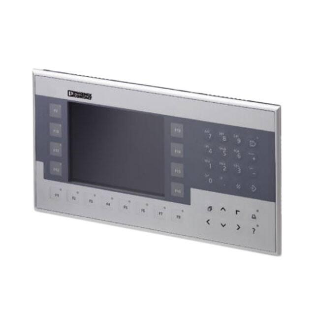
Product description
The operator terminals OT 3M, OT 4M and OT 6M are part
of a modern, scalable and seamless HMI family. Through
the use of a comprehensive range of functions, the operator
terminals provide an innovative operating concept for
complex machine visualizations. The operator terminals
have full-graphics 3", 4" or 6" displays. Each operator
terminal is equipped with one Ethernet interface and two
USB interfaces.
Make sure you always use the latest documentation.
It can be downloaded at www.download.phoenixcontact.com.
A conversion table is available on the Internet at www.download.phoenixcontact.com/general/7000_en_00.pdf.
This data sheet is valid for the products listed on the following page:
�OT 3M, OT 4M, OT 6M
Table of contents
1
Product description..................................................................................................................... 1
2
Ordering data.............................................................................................................................. 3
3
Technical data ............................................................................................................................ 3
4
Mounting..................................................................................................................................... 5
5
Housing dimensions ................................................................................................................... 6
5.1
5.2
5.3
6
OT 3M operator terminal ................................................................................................................................ 6
OT 4M operator terminal ................................................................................................................................ 7
OT 6M operator terminal ................................................................................................................................ 8
Switching on ............................................................................................................................... 9
6.1
6.2
6.3
Loading process within the Windows CE operating system ........................................................................... 9
Normal operating mode.................................................................................................................................. 9
Setup Main operating mode ......................................................................................................................... 10
7
Display.......................................................................................................................................14
8
Interfaces...................................................................................................................................14
9
Interface assignment .................................................................................................................15
9.1
9.2
9.3
Supply voltage ............................................................................................................................................. 15
USB ............................................................................................................................................................. 15
Ethernet........................................................................................................................................................ 15
10 Diagnostic LEDs ........................................................................................................................16
11 VISU+ ........................................................................................................................................17
12 General user notes ....................................................................................................................19
13 Restrictions for operator terminals .............................................................................................19
14 Keyboard ...................................................................................................................................20
15 Insert strips ................................................................................................................................23
7312_en_04
PHOENIX CONTACT
2
�OT 3M, OT 4M, OT 6M
2
Ordering data
Products
Description
Type
Order No.
Pcs./Pkt.
– With 3" FSTN display
OT 3M
2985123
1
– With 4" FSTN display
OT 4M
2985136
1
– With 6" FSTN display
OT 6M
2985149
1
Documentation
Description
Type
Order No.
Pcs./Pkt.
Quick Start Guide
UM QS EN OT TP
2888903
1
Operator terminal with integrated runtime of VISU+ visualization software
3
Technical data
Electrical data
OT 3M
OT 4M
OT 6M
Supply voltage
24 V DC (SELV according to DIN EN 61131)
Residual ripple
10%, maximum
Minimum voltage
18 V
Maximum voltage
30 V
Current consumption (at 24 V, typical)
0.25 A
Current consumption (maximum)
0.35 A
Connected load
6W
Fuse
Semiconductor fuse, self-resetting
Protection against polarity reversal
Integrated
Ethernet
X5 Ethernet
10/100Base-T
USB
In accordance with the "Universal Serial Bus Specification Rev. 2.0"
X9, X10 host
Minimum:
Maximum:
Maximum output current:
1.5 Mbps
12 Mbps
100 mA per output
Central processing unit
Central processing unit
RISC ARM9
Clock frequency
200 MHz
Other features
Watchdog timer, realtime clock, battery monitoring
7312_en_04
PHOENIX CONTACT
3
�OT 3M, OT 4M, OT 6M
Memory
Application memory
8 Mbytes
Flash
32 Mbytes
SDRAM
64 Mbytes
Connection method
Network
Ethernet (10/100 Mbps), RJ45
USB interface
2 x USB 2.0
Climatic data
Temperature (operation)
0°C ... 50°C
Ambient temperature (storage/transport)
-25°C ... +70°C
Relative humidity (operation and storage)
10% ... 95%, no condensation
Standards and directives
Noise immunity
DIN EN 61000-4-2
DIN EN 61000-4-3
DIN EN 61000-4-4
DIN EN 61000-4-5
DIN EN 61000-4-6
DIN EN 61000-6-2
Noise emission
DIN EN 55011 limit value class A
DIN EN 55022 limit value class A
DIN EN 6100-6-4
Equipment requirement
DIN EN 61131-2
Storage and transport
DIN EN 61131-2
Power supply units
DIN EN 61131-2
Electromagnetic compatibility
2004/108/EC (including all applicable modifications)
Degrees of protection
DIN EN 60529
Impact load, shocks
DIN EN 60068-2-27
Sinusoidal vibrations
DIN EN 60068-2-6
This device is classified as Class A equipment. It may cause radio interference in residential areas. In such cases, the operator may be held
liable for taking appropriate measures and for the incurrence of costs.
Housing and front plate
OT 3M
Housing
Front plate, natural anodized aluminum (H x W x D)
96 x 144 x 5 mm
Front foil
Grommet
Mounting cutout (H x W)
Installation depth
7312_en_04
OT 6M
205 x 155 x 5 mm
160 x 300 x 5 mm
Polyester foil
Circumferential rubber grommet on the rear
82 x 136 mm
199 x 139 mm
152 x 292 mm
46 mm, approximately
43 mm, approximately
43 mm, approximately
Degrees of protection
Total weight
OT 4M
Sheet steel, galvanized
Front: IP65; rear: IP20
500 g, approximately
800 g, approximately
1300 g, approximately
PHOENIX CONTACT
4
�OT 3M, OT 4M, OT 6M
4
Mounting
When mounting the operator terminal, leave
a circumferential gap of at least 30 mm in
order to provide sufficient air circulation.
The device enables quick and easy mounting from the rear.
Ideally, mounting should be in control panels with a plate
thickness of approximately 1 mm to 6 mm.
1. Push the device through the mounting cutout from the
front.
If the operator terminal is mounted
horizontally, please note that additional heat
sources may cause a build-up of heat below
the operator terminal.
Provide sufficient heat dissipation!
Please observe the permissible temperature
range specified in the technical data when
operating the device.
In order to ensure the specified degree of
protection, make sure that the grommet lies
flat against the mounting surface and the
threaded pins of the mounting brackets are
tightened uniformly.
Figure 1
2.
3.
7312_en_04
Mounting with mounting bracket
Place the mounting brackets in the appropriate slots (1)
and pull the brackets downwards until they snap into
place (2).
Secure the device using the threaded pins (3).
PHOENIX CONTACT
5
�OT 3M, OT 4M, OT 6M
5
Housing dimensions
5.1
OT 3M operator terminal
Figure 2
1
2
3
4
5
Front and side view of the OT 3M with dimensions
Mounting bracket
Threaded pin
Mounting surface, 1 mm to 6 mm thick
Circumferential grommet
Front plate
7312_en_04
PHOENIX CONTACT
6
�OT 3M, OT 4M, OT 6M
5.2
OT 4M operator terminal
Figure 3
1
2
3
4
5
Front and side view of the OT 4M with dimensions
Mounting bracket
Threaded pin
Mounting surface, 1 mm to 6 mm thick
Circumferential grommet
Front plate
7312_en_04
PHOENIX CONTACT
7
�OT 3M, OT 4M, OT 6M
5.3
OT 6M operator terminal
Figure 4
1
2
3
4
5
Front and side view of the OT 6M with dimensions
Mounting bracket
Threaded pin
Mounting surface, 1 mm to 6 mm thick
Circumferential grommet
Front plate
7312_en_04
PHOENIX CONTACT
8
�OT 3M, OT 4M, OT 6M
6
Switching on
The operator terminal is equipped with the Windows CE
operating system suitable for VISU+ visualization runtime.
6.1
Loading process within the Windows CE
operating system
The operator terminal allows you to modify the configuration
during the startup phase using buttons.
The operator terminal has two operating modes:
– Normal (no button pressed)
– Setup Main (Press For Setup Main Menu button
pressed)
6.2
Normal operating mode
The AppStarter.exe program is started from the internal
flash memory.
Admin
Press For Setup Main Menu
Display after startup
Please note that the device can only be reached
via Ethernet after an Ethernet address has been
assigned.
7312_en_04
PHOENIX CONTACT
9
�OT 3M, OT 4M, OT 6M
6.3
Setup Main operating mode
Press the Press For Setup Main Menu button during the
startup phase to start the Setup Main operating mode.
To transfer data and settings to another device,
proceed as follows:
1. "Copy to USB" on current device.
2. "Copy to Flash" on destination device.
3. Select "Backup" directory.
.
Setup Main
Update
Exit
Touch Screen
& Registry
Settings
Network
Settings
OPC ResEdit
The device is restarted.
4. "Import Settings" on destination device.
Update, Copy USB Stick, Copy to Flash:
Update
Copy USB
Stick
Copies the data from the USB stick to the internal flash file
system. The root, backup or any other directory can be
selected.
Home
Update Image
Update
Bootloader
Selection
Root
Copy USB Stick
Copy to Flash
Home
Backup
Copy to USB
Import
Settings
XYZ (any)
Touch Screen & Registry
Save Registry
Settings
Home
Update, Copy USB Stick, Copy to USB:
Change
Display Mode
Start
Calibration
Copies the contents of the flash file system to the backup
directory of the USB stick. Protected system files are
excluded. A log file is also copied, which can be used to
restore system settings via the "Import Settings" menu item.
SNTP Settings
SNTP Settings
Server
myserver.myhost.local
Interval [minutes]
OK
Current Mode
A
A
A
A
7312_en_04
Update, Registry
Update, Copy USB Stick, Import Settings:
5
Cancel
Change Display Mode
Figure 5
Function
All files (no directories) of the root
directory are copied to the root directory of
the flash memory.
The contents of the directory are copied to
the root directory of the flash memory.
The selected directory (including
subdirectories) is copied 1:1 to the flash
memory.
Cancel
An automatically generated log file can be used to restore
system settings. If the backup directory of the USB stick
contains a corresponding log file, the settings can be
restored.
This is only possible when using identical types of device.
OK
Update, Update Image:
LCD Saver
If the image subdirectory of the memory stick contains an
"xxxx.nb0" file, then this file is used to perform the image
update. There must only be one "xxxx.nb0" file in this
directory.
During this procedure flash registry is deactivated. This
means that "image" is operated with a new default registry.
PHOENIX CONTACT
10
�OT 3M, OT 4M, OT 6M
Update, Update Bootloader:
If the bootloader subdirectory of the memory stick contains
an "xxxx.nb0" file, then this file is used to perform the
bootloader update. There must only be one "xxxx.nb0" file in
this directory.
The user is informed after every successful update.
Registry, Save Registry Settings:
The complete registry is stored.
This entry is password-protected.
Registry, Change Display Mode:
Settings of display orientation.
This entry is password-protected.
Registry, Start Calibration:
Touch calibration is initiated. After calibration the values
must be saved via "Save Registry Settings".
This entry is password-protected.
Registry, SNTP Settings:
You can enter the address of an Intranet or Internet time
server. Enter the synchronization interval in minutes.
This entry is password-protected.
7312_en_04
PHOENIX CONTACT
11
�OT 3M, OT 4M, OT 6M
Setup Main
Update
Exit
Touch Screen
& Registry
Settings
Network
Settings
OPC ResEdit
All addresses must be entered in the format
"xxx.xxx.xxx.xxx".
Numbers less than 100 must be filled with leading
zeros.
(Example: 192.168.42.1 -> 192.168.042.001)
Network Settings
TCP/IP Info
Home
Fix Settings
FTP Settings
DHCP
Device Name
Network Settings, Fix Settings, IP Address:
TCP-IP Info
Enter an IP address and the subnet mask.
After confirming the information, DHCP is automatically
deactivated.
MAC: 0-0-00-0-0-00
IP: 192.168.100.82
Mask: 255.255.255.0
Device Name: MyName
DHCP enabled
Gate: 0.0.0.0
Fix Settings
IP Address
This entry is password-protected.
Home
Gateway
DNS
Network Settings, Fix Settings, Gateway:
WINS
Define the default gateway.
After confirming the information, DHCP is automatically
deactivated.
IP Address
IP Address
000.000.000.000
Subnet Mask
000.000.000.000
OK
Cancel
This entry is password-protected.
Gateway
Change Default Gateway
Network Settings, Fix Settings, DNS:
000.000.000.000
OK
Here you can enter a primary and a secondary DNS server
address.
After confirming the information, DHCP is automatically
deactivated.
Cancel
DNS
Primary DNS
000.000.000.000
Secondary DNS
000.000.000.000
OK
Cancel
This entry is password-protected.
WINS
Primary WINS
000.000.000.000
Secondary WINS
000.000.000.000
OK
Network Settings, Fix Settings, WINS:
Here you can enter primary and secondary WINS
addresses.
After confirming the information, DHCP is automatically
deactivated.
Cancel
DHCP
DHCP enabled
Save registry and restart device to
work with new parameters
FTP Settings
Add new user
This entry is password-protected.
Home
List all users
Network Settings, Current IP:
Delete a user
Displays the current IP address, subnet mask, device name,
DHCP status, and gateway.
Add new user / Delete a user
Enter User
MyName
Enter Password
****
Confirm Password
OK
Device Name
Network Settings, DHCP:
****
Cancel
Password
****
Confirm
****
Enter Device Name
MyName
OK
Figure 6
Cancel
Network Settings
OK
Cancel
This menu item is used to activate the DHCP service. The
settings must be saved when exiting the menu or via "Save
Registry Settings".
This entry is password-protected.
Network Settings, Device Name:
Specify a device name with a maximum of 15 characters.
The device can be accessed by the device name instead of
the IP address by using an FTP connection.
This entry is password-protected.
7312_en_04
PHOENIX CONTACT
12
�OT 3M, OT 4M, OT 6M
Settings, Contrast:
Settings
Contrast
In the Setup Main operating mode display, default values
are used for contrast and brightness. This ensures display
even in the event of faulty values. Changing a value requires
confirmation in an additional dialog box. The values are not
accepted if Cancel is pressed or confirmation does not take
place within 5 seconds.
This entry is password-protected. Depending on the display
type, different values can be modified:
Home
Date / Time
Printer
Password
Information
Contrast
Contrast
Brightness
15
15
Color Depth
8 bpp
16 bpp
OK
Apply
Cancel
Date / Time
Current Time
OK
X
Display type
STN (mono)
STN (color)
TFT
Contrast
X
X
-
Brightness
X
X
15:00:00 AM
Settings, Date / Time:
Time Zone
(GMT +01:00) Amsterdam, Berlin, Bern, Rome
Automatically adjust clock for daylight saving
Set the date and time. Press Refresh to update the values.
Apply
Settings, Password:
Password
The password can be activated, deactivated or redefined.
When the password is activated, all password-protected
dialog boxes can only be accessed by prior entry of
password.
This entry is password-protected.
Current Password
Enable Password
Change
OK
Cancel
Printer
Settings, Information:
USB Printer
The following information is output: serial number, part
number, image version, image date, flash size, SRAM size,
and PLC/Visu RAM size.
Network Printer
Path:
OK
Cancel
Information
OPC ResEdit:
SNR: 1023456789
Prod.ID: 80870.030
Image_OffenePlattform_AX_HMI_EP
9307_CE5.00
Built: Sep 12 2007 13:23:28
Flash Size: 32 MB
SRAM Size: 512 kB
PLC / VISU RAM: 0 / 460 kB
Busclock: 99 MHz
Click OK to go back to main
Figure 7
The OPC Resource Editor is started. Resource, type and
parameter settings can be made.
This entry is password-protected.
The addition "-ip" must always be retained.
(Example: -ip192.168.42.1)
Setup Main operating mode
Setup Main
Update
Exit
Touch Screen
& Registry
Settings
Network
Settings
OPC ResEdit
Add
ILC 3x0
-ip127.0.0.1
Del
Save
Close
Figure 8
7312_en_04
OPC ResEdit
PHOENIX CONTACT
13
�OT 3M, OT 4M, OT 6M
7
Display
DANGER: Poisoning
If the display is damaged, avoid direct contact with skin, and do not ingest any liquids or inhale any gases.
DANGER: Chemical burns
If the display is damaged, avoid direct contact with skin, and do not ingest any liquids or inhale any gases.
Depending on its design, the operator terminal is equipped with different displays.
Touch screen
The operator terminal has a resistive 4-wire touch screen, which is used for its operation.
NOTE: Damage
Pointed or sharp objects, such as pins or fingernails, may cause irreparable damage to the touch screen.
Therefore, only use your fingertips or the tools specified in the technical data for operating the touch screen.
8
Interfaces
Several interfaces are located on the bottom of the operator terminal.
Figure 9
1
2
3
Interfaces of the OT 3M, OT 4M, and OT 6M operator interfaces
Female connector X5 (Ethernet)
Female connector X9, X10 (USB host - type A)
Male connector X1 (supply voltage)
7312_en_04
PHOENIX CONTACT
14
�OT 3M, OT 4M, OT 6M
9
Interface assignment
9.2
USB
DANGER: Hazardous contact voltage
In electrical systems, hazardous voltages may
occur posing a danger to humans. There is a risk
of electric shock when touching live parts.
Work must only be carried out by qualified
personnel familiar with the required safety
measures.
NOTE:
Provide a separate cable for protective grounding
at the threaded bolt. The cable must have a
minimum cross section of 1.5 mm² and must be
as short as possible.
9.1
Figure 11
Pin
1
2
3
4
Two USB host interfaces
Designation
VCC (+5 V DC)
Data–
Data+
GND
Use a fine strand cable with a minimum cross
section of 0.75 mm² and a maximum cross
section of 2.5 mm² for the supply voltage.
Supply voltage
For the specification of a suitable cable, please
refer to the "Universal Serial Bus Specification
Rev. 2.0".
Figure 10
Supply voltage
Pin
1
Designation
Function
Low-noise ground
2
3
0V
+24 V DC
0 V supply voltage
24 V DC supply voltage
Use a fine strand cable with a minimum cross
section of 0.75 mm² and a maximum cross
section of 2.5 mm² for the supply voltage.
The maximum cable length for the cable used is
2.5 m.
9.3
Ethernet
Figure 12
Pin
1
2
3
4
5
6
7
8
Ethernet interface
Designation
Tx+
TxRx+
n.c.
n.c.
Rxn.c.
n.c.
Function
Transmit data, positive polarity
Transmit data, negative polarity
Receive data, positive polarity
Not connected
Not connected
Receive data, negative polarity
Not connected
Not connected
Use a category 5 (CAT 5) twisted pair cable. The
maximum cable length is 100 m.
For additional information, please refer to the
IEEE 802.3 standard.
7312_en_04
PHOENIX CONTACT
15
�OT 3M, OT 4M, OT 6M
10
Diagnostic LEDs
Ethernet diagnostic LEDs are located at the Ethernet
interface of the operator terminal.
Figure 13
Arrangement of the Ethernet diagnostic LEDs
No. Designa- Color State
tion
1
XMT
Green On
Off
Flashing
2
RCV
7312_en_04
Yellow On
Off
Flashing
Function
Link active
Link inactive
Transmitting/
receiving
Full duplex mode
Half duplex mode
Collision detected
PHOENIX CONTACT
16
�OT 3M, OT 4M, OT 6M
11
Recommendations to improve performance
VISU+
VISU+ is an industrial visualization software which can be
used on all hardware platforms under Windows CE and XP
operating systems.
The TPxx series uses Windows CE as its operating system.
The visualization functionality is limited under Windows CE.
In addition, performance is reduced by the choice of
hardware.
Please observe the following restrictions:
• Lower speed
• Less memory space
• Limited trending
• Limited data logging
• Limited alarming
• Processing of data amount (hardware-dependent)
• Graphical elements of the VISU+ library (e.g., tank
views with traverses) cannot be completely displayed.
VISU+ functions
I/O variables in bytes (tags)
Graphical interface and objects
Alarms
Short-cut and menu editor
Virtual pad (for touch screen)
Historical log for events
Dynamic language management
General logic
VBA multithreading
Trending
Recipe data logger
Reporting
Networking
Statistic alarms
SMS/voice/fax/e-mails
Modem services
Driver tapi
Charts
OPC client
Runtime user management
7312_en_04
4096
Limited
Limited
Yes
Yes
Limited
Yes
Yes
Yes
Limited
Limited
Not available
Yes
Not available
Not available
Not available
Yes
Yes
Not available (ARM9)
Yes (XScale)
1.
Reducing the page switchover time (page clearing)
To ensure a rapid switchover time between the pages to be
visualized, the "Not destroyable" option should be set in the
project file. Using this setting the page remains in RAM. The
RAM assignment directly depends on both the displayed
page size and the total number of pages. A RAM area of
approximately 12 ... 13 MB is available for the saving of
pages. A total of approximately 40 ... 50 pages can be saved
in this area, depending on the page memory requirements.
For the operator terminal templates, the "Not destroyable"
option is set by default.
When starting the runtime environment, only pages with the
"Not destroyable" option activated will be preloaded into
RAM provided that the option "Preload process images" has
been selected for the project.
In this case, the starting time will be prolonged once by the
page load times.
2.
Using IL (instruction list)
Assigning an IL script to a page requires a RAM area of
approximately 800 kB. Due to the limited memory capacity,
it is only possible to preload a maximum of 10 pages. In
addition, the script runs in the background if the "Not
destroyable" option is selected.
The scripts of all pages loaded into RAM are processed in
parallel. Even the scripts stored in background are
processed. This may lead to undesired interactions.
For the global use of IL scripts within a project, the engine
should be stored on the overview page.
To avoid confusion in the IL scripts, unused
pages should always be "cleared" if they contain
IL scripts possibly affecting other pages.
3.
Using VBA (Visual Basic for Applications)
Assigning VBA to a page requires a RAM area of
approximately 800 kB. Due to the limited memory capacity,
it is only possible to preload a maximum of 10 pages. In
addition, VBA runs in the background if the "Not
destroyable" option is selected.
For the global use of data within a project, the engine should
be stored on the overview page.
PHOENIX CONTACT
17
�OT 3M, OT 4M, OT 6M
4.
Heap management
VISU+ system variables
Heap management is used for memory management using
the VISU+ runtime environment. The request and release of
memory areas is both dynamic and unpredictable.
When creating a new VISU+ project, you should always
apply the templates of the chosen HMI operator terminal,
which are provided by the program.
If there is no automatic garbage collection, the
fragmentation of the total available memory may lead to new
memory requirements not being able to be met even though
the sum of available free memory would, theoretically, still
be high enough.
Using device-specific templates ensures that the devicedependent system variables are created properly and the
HMI operator terminal is supported in its entire performance
range (see also Section "Keyboard" on page 20).
Heap management can be activated to ensure a more
efficient memory management and thus reduced access
times.
In the program, the system variables are managed as a byte
(8-bit) sequence.
For activating the heap management, proceed as follows:
1. Start the project file on the PC.
2. Open all project pages and options of the project file.
3. Stop the project on the PC.
4. Activate heap management by selecting the Set value
of last start option.
The values automatically determined by the heap
management are set.
Figure 14
7312_en_04
Detail view, VISU+ system variables
OT 3M
PHOENIX CONTACT
18
�OT 3M, OT 4M, OT 6M
12
General user notes
Error message
Error message
Flash full
Figure 15
13
Remedy
Delete any data in the flash memory
that is no longer needed.
(e.g., via FTP access)
To swap out memory data, use a
USB memory extension, if necessary.
Example, error message
Restrictions for operator terminals
VISU+ uses buttons which support the following operator
functions:
Pushbutton functionality
By pressing the button once, a log 1 signal is generated. The
signal remains active as long as the button is pressed. The
signal state returns to log 0 when the button is released.
Switch functionality
By pressing the button once, a log 1 signal is generated. By
pressing the button once again, the signal state returns to
log 0.
Command functionality
In conjunction with the onboard keys, only the "Release key"
command trigger is processed.
7312_en_04
PHOENIX CONTACT
19
�OT 3M, OT 4M, OT 6M
14
Keyboard
The keys are protected by an embossed polyester foil resistant to environmental influences.
The 0 and ()° key is used for data input. Pressing the key once provides the character 0. Pressing and holding
the key for approximately 2 seconds allows you to select between the characters ()°.
The 1 and STU key is used for data input. Pressing the key once provides the character 1. Pressing and holding
the key for approximately 2 seconds allows you to select between the characters S, T, U, s, t, and u.
The 2 and VWX key is used for data input. Pressing the key once provides the character 2. Pressing and holding
the key for approximately 2 seconds allows you to select between the characters V, W, X, v, w, and x.
The 3 and YZ% key is used for data input. Pressing the key once provides the character 3. Pressing and holding
the key for approximately 2 seconds allows you to select between the characters Y, Z, %, y, z, and %.
The 4 and JKL key is used for data input. Pressing the key once provides the character 4. Pressing and holding
the key for approximately 2 seconds allows you to select between the characters J, K, L, j, k, and l.
The 5 and MNO key is used for data input. Pressing the key once provides the character 5. Pressing and holding
the key for approximately 2 seconds allows you to select between the characters M, N, O, m, n, and o.
The 6 and PQR key is used for data input. Pressing the key once provides the character 6. Pressing and holding
the key for approximately 2 seconds allows you to select between the characters P, Q, R, p, q, and r.
The 7 and ABC key is used for data input. Pressing the key once provides the character 7. Pressing and holding
the key for approximately 2 seconds allows you to select between the characters A, B, C, a, b, and c.
The 8 and DEF key is used for data input. Pressing the key once provides the character 8. Pressing and holding
the key for approximately 2 seconds allows you to select between the characters D, E, F, d, e, and f.
The 9 and GHI key is used for data input. Pressing the key once provides the character 9. Pressing and holding
the key for approximately 2 seconds allows you to select between the characters G, H, I, g, h, and i.
The decimal point and :?! key is used for data input. Pressing the key once provides the decimal point. Pressing
and holding the key for approximately 2 seconds allows you to select between the characters :, ?, !, :, ?, !.
The Plus key is used to increment numeric values.
The Plus and key is used for data input. Pressing the key once provides the character +. Pressing and
holding the key for approximately 2 seconds allows you to select between the characters .
The Minus key is used to decrement numeric values.
The Minus and \*/ key is used for data input. Pressing the key once provides the character -. Pressing and
holding the key for approximately 2 seconds allows you to select between the characters \*/.
7312_en_04
PHOENIX CONTACT
20
�OT 3M, OT 4M, OT 6M
Control keys
The Cursor left key is used for navigation.
The Cursor right key is used for navigation.
The Cursor down key is used for navigation.
The Tab key is used to navigate between text fields and buttons.
The LEDs are controlled via the "LED_TAB" VISU+ system variable.
The Enter key is used to confirm buttons and dialog boxes.
The Del key is used to delete characters in the text fields.
The Cursor home / Pos 1 key is used for navigation.
Special keys
The function of the Scroll key can be freely assigned using Visu+ and is configured as F17.
The function of the Print key can be freely assigned using Visu+ and is configured as F18.
The LED is controlled via the "LED_PRINT" VISU+ system variable.
The function of the Help key can be freely assigned using Visu+ and is configured as F19.
The LED is controlled via the "LED_HELP" VISU+ system variable.
Function keys
The function of the function keys can be freely assigned using Visu+.
The F1 - F12 function keys are supported depending on the HMI operator terminal used.
The relevant LED is controlled via the associated "LED_Fxx_COMMAND" VISU+ system variable.
We recommend the use of an external USB keyboard to make settings on the OT 3M. This can be used, for
example, to define the device name. The + and – keys can be used to enter numeric values in the operator
terminals.
7312_en_04
PHOENIX CONTACT
21
�OT 3M, OT 4M, OT 6M
Insert strips for the function keys
The insert strips can be replaced when the operator terminal
is installed or removed. By inserting the strips from the rear
of the front plate, the functionality of the specified sealing will
not be affected. A set of insert strips is supplied as standard.
For labeling, use the following:
Single pieces, prototypes:
Labeling with a permanent marker pen
Small series:
Copying foil (thickness ≤ 70 µm) with laser print
Large series
Customer-specific labeled insert strips
7312_en_04
PHOENIX CONTACT
22
�OT 3M, OT 4M, OT 6M
15
Insert strips
Figure 16
Figure 17
7312_en_04
Position of the insert strips in the OT 3M
Figure 18
Set of insert strips for the OT 3M
Figure 19
Set of insert strips for the OT 4M
Position of the insert strips in the OT 4M
PHOENIX CONTACT
23
�OT 3M, OT 4M, OT 6M
Figure 20
Position of the insert strips in the OT 6M
Figure 21
Set of insert strips for the OT 6M
7312_en_04
PHOENIX CONTACT GmbH & Co. KG • 32823 Blomberg • Germany • Phone: +49-(0) 5235-3-00
PHOENIX CONTACT • P.O.Box 4100 • Harrisburg • PA 17111-0100 • USA • Phone: +717-944-1300
www.phoenixcontact.com
24
�