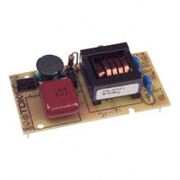
DC-AC INVERTER UNIT
CXA-M10A-L (6W SINGLE & DUAL OUTPUTS, PCB MOUNTABLE)
DESCRIPTION : TDK DC/AC Inverter, CXA-series, are low-noise, high frequency power sources developed for driving Cold Cathode Fluorescent Lamps operating at 20~80 kHz. These inverters are designed to handle a wide range of lamp characteristics.
(STANDARD)
FEATURES : Constant current output ensures compatibility with a wide range of discharge lamps. High efficiency resonant circuitry produces low-noise, sinusoidal-wave output. One-lamp/two-lamp combined-use capability allows use in four different configurations. Common ground or floating bulb configurations. Compact size and light weight facilitate PC board mounting. High Efficiency (80%)
TEMPERATURE & HUMDITY : Operating Temperature Range Storage Temperature Range Humidity
DIMENSIONS :
29 Max 20.32±0.2 3 Min 16.5 Max
-10 °C ~ +60°C -20 °C ~ +85°C 95 %RH max (No dew)
Unit : mm Weight: 21.0g typ.
1
2 Jumper
50.8±0.2
(*1)
56 Max
Pin 1 2 3 4 5
Symbol Vin GND Iout1 Iout2 Iout-ret
Note 0 ~ 6 Vdc 0 Vdc
5
4
3 (2) 5x 0.64±0.07
Bottom View
*1 Remove for Isolated Ground
Power Systems – The Power Solution
Web: Email: www.Power-Systems.de Info@Power-Systems.de
Page ( 1 / 4 )
(20)
(6)
Unit : mm
Address: Dörnet 8 ; 74360 Ilsfeld-Auenstein / Germany Tel. : + 49 / 70 62 / 67 59 - 6 Fax: + 49 / 70 62 / 67 59 - 80
VER, 25 November 2003
All specification are subject to change without notice.
�DC-AC INVERTER UNIT
CXA-M10A-L (6W SINGLE & DUAL OUTPUTS, PCB MOUNTABLE) (STANDARD)
CONNECTOR CONFIGURATION:
ABSOLUTE MAXIMUM RATINGS:
Pin No. Symbols Vin 1 2 3 4 5 GND OUT1 OUT2 OUT GND
Ratings 5V 0V 400Vrms 400Vrms 0V
Items Input Voltage Output Power
Symbols Vin Pout
Specification 0~6.0 6
Unit VDC W
ELECTRICAL CHARACTERISTICS:
Items Output Current Input Current Frequency Open Circuit Voltage Output Current Input Current Frequency Open Circuit Voltage Output Current Input Current Frequency Open Circuit Voltage Output Current Input Current Frequency Open Circuit Voltage
Symbols Iout Iin F Vopen Iout Iin F Vopen Iout Iin F Vopen Iout1 / Iout2 Iin F Vopen
Conditions Vin [V] 5±0.05 5±0.25 5±0.25 5±0.25 5±0.25 5±0.05 5±0.25 5±0.25 5±0.25 5±0.25 5±0.05 5±0.25 5±0.25 5±0.25 5±0.25 5±0.05 5±0.25 5±0.25 5±0.25 5±0.25 Ta [°C] 23±5 -10~60 -10~60 -10~60 -10~60 23±5 -10~60 -10~60 -10~60 -10~60 23±5 -10~60 -10~60 -10~60 -10~60 23±5 -10~60 -10~60 -10~60 -10~60 RL [KΩ] 40 30~50 30~50 30~50 ∞ 67 50~84 50~84 50~84 ∞ 80 60~100 60~100 60~100 ∞ 80 60~100 60~100 60~100 ∞ 9 8 -
Specification Min. Typ. 10 10 1000 28 1200 6 6 600 32 1200 5 5 600 28 1200 5/5 5/5 1000 28 1200 Max. 11 12 1500 33 6.5 7.1 1000 37 5.4 5.9 900 33 5.5/5.5 6/6 1500 33 -
Unit mArms mA DC kHz Vrms mArms mA DC kHz Vrms mArms mA DC kHz Vrms mArms mA DC kHz Vrms
Connection
1
23 1000 5.1 4.5 27 1000 4.2 3.7 23 1000 4.5/4.5 4/4 23 1000
2
3
4
Power Systems – The Power Solution
Web: Email: www.Power-Systems.de Info@Power-Systems.de
Page ( 2 / 4 )
Address: Dörnet 8 ; 74360 Ilsfeld-Auenstein / Germany Tel. : + 49 / 70 62 / 67 59 - 6 Fax: + 49 / 70 62 / 67 59 - 80
VER, 25 November 2003
All specification are subject to change without notice.
�DC-AC INVERTER UNIT
CXA-M10A-L (6W SINGLE & DUAL OUTPUTS, PCB MOUNTABLE) (STANDARD)
APPLICATION Connection 1
Pin1 (Vin) Pin3 (out1)
Connection 3
Pin1 (Vin) Pin3 (out1)
Vin
Pin4 (out2)
CCFL
Vin
Pin4 (out2)
CCFL
Pin2 (GND)
Pin5 (out GND)
Pin2 (GND)
Pin5 (out GND)
Connection 2
Pin1 (Vin) Pin3 (out1)
Connection 4
Pin1 (Vin) Pin3 (out1)
CCFL2 Vin Pin4 (out2) CCFL Vin Pin4 (out2) CCFL1
Pin2 (GND)
Pin5 (out GND)
Pin2 (GND)
Pin5 (out GND)
Note 1. Note 2.
For circuit connection, please prefer to test circuit diagram. Please use minimum of 2mm clearance (all directions) between inverter high voltage area and any conductors. Please refer to mechanical drawing for marking of high voltage area. Open voltage (strike voltage) is measured across the transformer secondary winding at no load as the reading at the output connector would be less than the actual value. If the start up voltage falls below Cold Cathode Tube strike voltage, the CCFL will not light up easily specially at lower ambient temperature. Please review mounting instruction to avoid any abnormal operation due to coupling/leakage capacitance of inverter high voltage area to any surrounding conductor. For operation in floating mode, please remove jumper (J1) on top side of PCB that pin2 and pin5. To prevent electrical discharge from high voltage area, please use non-conductive fastener in U mounting hole.
Note 3.
Note 4.
Note 5. Note 6.
Power Systems – The Power Solution
Web: Email: www.Power-Systems.de Info@Power-Systems.de
Page ( 3 / 4 )
Address: Dörnet 8 ; 74360 Ilsfeld-Auenstein / Germany Tel. : + 49 / 70 62 / 67 59 - 6 Fax: + 49 / 70 62 / 67 59 - 80
VER, 25 November 2003
All specification are subject to change without notice.
�DC-AC INVERTER UNIT
CXA-M10A-L (6W SINGLE & DUAL OUTPUTS, PCB MOUNTABLE)
TEST CIRCUIT
(STANDARD)
Power Systems – The Power Solution
Web: Email: www.Power-Systems.de Info@Power-Systems.de
Page ( 4 / 4 )
Address: Dörnet 8 ; 74360 Ilsfeld-Auenstein / Germany Tel. : + 49 / 70 62 / 67 59 - 6 Fax: + 49 / 70 62 / 67 59 - 80
VER, 25 November 2003
All specification are subject to change without notice.
�
很抱歉,暂时无法提供与“CXA-M10A-L”相匹配的价格&库存,您可以联系我们找货
免费人工找货