LD41__60
Powerex, Inc., 173 Pavilion Lane, Youngwood, Pennsylvania 15697 (724) 925-7272
www.pwrx.com
Description:
OUTLINE DRAWING
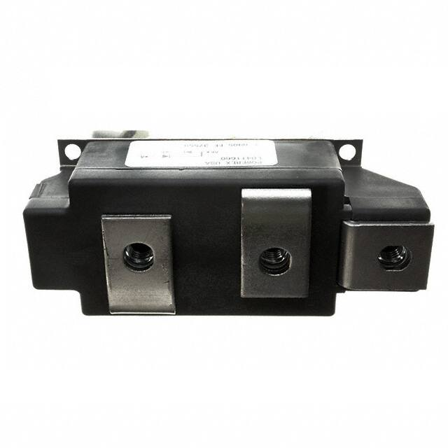
Powerex Dual Diode Modules are
designed for use in applications
requiring rectification and isolated
packaging. The modules are isolated
for easy mounting with other
components on a common heatsink.
TM
POW-R-BLOK has been tested and
recognized by the Underwriters
Laboratories.
A
R
B
C
J
F
K
L
Q - DIA. (4
TYP.)
G
H
P - M10 THD (3
TYP.)
M
E
N
2
1
3
CONNECTION DIAGRAM
Ordering Information:
Select the complete eight-digit
module part number from the table
below.
Example: LD412460 is a 2400V,
600 Ampere Dual Diode Isolated
TM
POW-R-BLOK Module.
LD41
LD41__60
Dual Diode
TM
POW-R-BLOK Module
600 Amperes / 800-2600 Volts
LD41 Outline Dimensions
S
Type
D
1
2
3
TM
POW-R-BLOK
Dual Diode Isolated Module
600 Amperes / Up to 2600 Volts
Voltage
Volts
(x100)
Current
Amperes
(x10)
08
10
12 to 26
60
Dimension
Inches
Millimeters
A
5.91
150.0
B
4.88
124.0
C
4.41
112.0
D
2.36
60.0
E
2.05
52.0
F
1.97
50.0
G
1.89
48.0
H
1.73
44.0
J
1.22
31.0
K
1.10
28.0
L
1.00
25.4
M
0.69
17.5
N
0.39
10.0
P
M10 Metric
M10
Q
0.26 Dia.
6.5 Dia.
R
0.24
6.0
S
0.12
3.0
T
.110 x .032
2.5 x 0.8
Features:
Electrically Isolated Heatsinking
Aluminum Nitride Isolator
Compression Bonded Elements
Metal Baseplate
Low Thermal Impedance
for Improved Current Capability
UL Recognized
Benefits:
No Additional Insulation
Components Required
Easy Installation
No Clamping Components
Required
Reduce Engineering Time
Applications:
Bridge Circuits
AC & DC Motor Drives
Battery Supplies
Power Supplies
Large IGBT Circuit Front Ends
Note: Dimensions are for reference only.
Revision Date: 08/01/2013
�LD41__60
Powerex, Inc., 173 Pavilion Lane, Youngwood, Pennsylvania 15697 (724) 925-7272
www.pwrx.com
TM
POW-R-BLOK
Dual Diode Isolated Module
600 Amperes / Up to 2600 Volts
Absolute Maximum Ratings
Characteristics
Conditions
Symbol
Units
Repetitive Peak Reverse Blocking Voltage
VRRM
up to 2600
V
Non-Repetitive Peak Reverse Blocking Voltage
(t < 5 msec)
RMS Forward Current
VRSM
VRRM + 100
V
IF(RMS)
950
A
Average Forward Current
180° Conduction, TC=106°C
IF(AV)
600
A
Peak One Cycle Surge Current, Non-Repetitive
Peak Three Cycle Surge Current, Non-Repetitive
60 Hz, 100% VRRM reapplied
50 Hz, 100% VRRM reapplied
60 Hz, 100%VRRM reapplied
IFSM
IFSM
IFSM
21000
19000
15,500
A
A
A
Peak Ten Cycle Surge Current, Non-Repetitive
60 Hz, 100% VRRM reapplied
IFSM
13,000
A
8.3 milliseconds
10 milliseconds
Operating Temperature
I2t
I2t
TJ
1,840,000
1,810,000
-40 to +150
A2 sec
A2 sec
°C
Storage Temperature
Tstg
-40 to +150
°C
55
6
110
12
1500
3.30
in. – Lb.
Nm
in. – Lb.
Nm
g
lb
3000
V
I2t for Fusing for One Cycle
Max. Mounting Torque, M6 Mounting Screw
Max. Mounting Torque, M10 Terminal Screw
Module Weight, Typical
V Isolation @ 25C
Vrms
Information presented is based upon manufacturers testing and projected capabilities.
This information is subject to change without notice.
The manufacturer makes no claim as to the suitability of use, reliability, capability,
or future availability of this product.
Revision Date: 08/01/2013
�LD41__60
Powerex, Inc., 173 Pavilion Lane, Youngwood, Pennsylvania 15697 (724) 925-7272
www.pwrx.com
TM
POW-R-BLOK
Dual Diode Isolated Module
600 Amperes / Up to 2600 Volts
Electrical Characteristics, TJ=25°C unless otherwise specified
Characteristics
Repetitive Peak Reverse Leakage Current
Peak On-State Voltage
Symbol
Test Conditions
Min.
IRRM
Up to 2600V, TJ=150°C
Max.
Units
40
mA
VFM
TJ=25°C, IFM=1500A
1.18
V
Threshold Voltage, Low-level
Slope Resistance, Low-level
V(TO)1
rT1
TJ = 150°C, I = 15%IF(AV) to πIF(AV)
0.747
0.243
V
mΩ
Threshold Voltage, High-level
Slope Resistance, High-level
V(TO)2
rT2
TJ = 150°C, I = πIF(AV) to IFSM
0.914
0.145
V
mΩ
VTM Coefficients, Full Range
TJ = 150°C, I = 15%IF(AV) to IFSM
VTM = A+ B Ln I +C I + D Sqrt I
A=
B=
C=
D=
5.05E-01
3.44E-02
8.13E-05
6.57E-03
Thermal Characteristics
Characteristics
Symbol
Max.
Units
0.0325
0.0650
°C/W
°C/W
Thermal Resistance, Junction to Case
RΘJ-C
Per Module, both conducting
Per Junction, both conducting
Thermal Impedance Coefficients
ZΘJ-C
ZΘJ-C= K1 (1-exp(-t/1))
K1 = 8.03E-04
1 = 3.39E-04
+ K2 (1-exp(-t/2))
K2 = 1.03E-02
2 = 3.15E-03
+ K3 (1-exp(-t/3))
K3 = 1.64E-02
3 = 1.06E-01
+ K4 (1-exp(-t/4))
Per Module
K4 = 3.75E-02
4 = 2.066
0.01
Thermal Resistance, Case to Sink Lubricated
RΘC-S
°C/W
Revision Date: 08/01/2013
�LD41__60
TM
POW-R-BLOK
Dual Diode Isolated Module
600 Amperes / Up to 2600 Volts
Powerex, Inc., 173 Pavilion Lane, Youngwood, Pennsylvania 15697 (724) 925-7272
www.pwrx.com
Maximum On-State Forward Voltage Drop
Maximum Transient Thermal Impedance
( Tj = 150 °C )
(Junction to Case)
5.00
0.07
•
0.06
Thermal Impedance - Zjc - °C/W
On-State Voltage - Vfm - Volts
•
4.00
3.00
2.00
1.00
0.05
0.04
0.03
0.02
0.01
0
0.001
0.00
10
100
1000
10000
100000
0.01
0.1
1
10
100
Time - t - Seconds
Instantaneous On-State Current - Ifm - Amperes
Maximum Allowable Case Temperature
Maximum On-State Power Dissipation
(Sinusoidal Waveform)
(Sinusoidal Waveform)
150
120°
•
600
180°
145
Max. Case Temperature - Tcase -°C
Max. Power Dissipation Per Diode - Watts
700
90°
500
60°
400
30°
15°
300
200
100
140
135
130
15°
125
30°
120
60°
115
90°
110
120°
105
100
0
0
100
200
300
400
500
600
0
700
100
200
300
400
500
600
700
Average On-State Current - If(av) - Amperes
Average On-State Current - If(av) - Amperes
Maximum Allowable Case Temperature
Maximum On-State Power Dissipation
(Rectangular Waveform)
(Rectangular Waveform)
1000
150
•
900
270°
800
360°
Max. Case Temperature - Tcase -°C
Max. Power Dissipation Per Diode - Watts
180°
•
180°
700
120°
90°
600
60°
500
30°
400
15°
300
200
100
140
130
15°
30°
120
60°
110
90°
120°
100
180°
270°
90
360°
•
0
80
0
200
400
600
800
Average On-State Current - If(av) - Amperes
1000
0
200
400
600
800
1000
Average On-State Current - If(av) - Amperes
Revision Date: 08/01/2013
�LD41__60
TM
POW-R-BLOK
Dual Diode Isolated Module
600 Amperes / Up to 2600 Volts
Powerex, Inc., 173 Pavilion Lane, Youngwood, Pennsylvania 15697 (724) 925-7272
www.pwrx.com
Powerex LD41--60 Pow-R-Blok 6-Pulse Bridge
4000
0.02
0.015
0.01
Total Power Dissipation vs Maximum Rated Output Current
4000
4000
3500
3500
3000
3000
2500
2500
2000
2000
1500
1500
1000
1000
Rth S-A (C/W)
3500
Total Power Dissipation (W)
3000
0.03
2500
0.04
0.05
2000
0.06
1500
0.08
0.10
1000
0.12
Total Power Dissipation (W)
0.025
0.15
0.20
500
500
500
0.30
0
0
0
20
40
60
80
100
120
140
0
500
1000
1500
0
2000
(C)
Maximum
Bridge Output
Six-Pulse Bridge Ambient
CircuitTemperature
Total Power
Dissipation & Maximum Rated Output
Current
WithCurrent
Sink(A)
to Ambient
Resistance of Heatsink as a Parameter.
Revision Date: 08/01/2013
�LD41__60
TM
POW-R-BLOK
Dual Diode Isolated Module
600 Amperes / Up to 2600 Volts
Powerex, Inc., 173 Pavilion Lane, Youngwood, Pennsylvania 15697 (724) 925-7272
www.pwrx.com
Maximum Surge Current Ratings - 60Hz
1.0
Duration of Surge (ms)
10.0
100.0
1000.0
Peak Surge Current (A)
100,000
Tj initial = 150oC
Vr = 0V
10,000
Vr = Vrrm
1,000
0.1
1
10
100
100.0
1000.0
Number of Cycles @ 60Hz
Maximum I2t Ratings - 60Hz
Duration of Surge (ms)
1.0
10.0
1.00E+08
Maximum I2t (A)
Tj initial = 150oC
Vr = 0V
1.00E+07
Vr = Vrrm
1.00E+06
1.00E+05
0.1
1
10
100
Number of Cycles @ 60Hz
Maximum Surge Ratings - 50Hz
Duration of Surge (ms)
1
10
100
1000
Peak Surge Current (A)
100,000
Tj initial = 150oC
Vr = 0V
10,000
Vr = Vrrm
1,000
0.1
1
10
100
100.0
1000.0
Number of Cycles @ 50Hz
Maximum I2t Ratings - 50Hz
Duration of Surge (ms)
1.0
10.0
1.00E+08
Maximum I2t (A)
Tj initial =
150oC
Vr = 0V
1.00E+07
Vr = Vrrm
1.00E+06
1.00E+05
0.1
1
10
100
Number of Cycles @ 50Hz
Revision Date: 08/01/2013
�