SCALE™-2 2SD300C17A3, 2SD300C17A3C
2SD300C17A3 and 2SD300C17A3C
Preliminary Datasheet
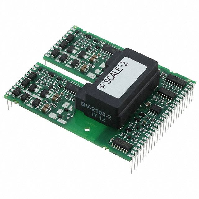
Dual-Channel High-quality and SCALE™-2 Driver Core
Abstract
The SCALE™-2 dual-driver core 2SD300C17A3 / 2SD300C17A3C (Coated version using ELPEGUARD SL 1307
FLZ/2 from Lackwerke Peters) is designed for applications in which high reliability is expected.
The use of Power Integrations' highly integrated SCALE-2 chipset allows 63% of the components to be
dispensed with compared to conventional drivers. This advantage is impressively reflected in increased
reliability (function and MTBF).
The 2SD300C17A3(C) combines a complete two-channel driver core with all components required for driving,
such as an isolated DC/DC converter, short-circuit protection, failure soft shut down, short pulse suppression
as well as supply voltage monitoring. Each of the two output channels is electrically isolated from the primary
side and the other secondary channel.
The driver provides a gate voltage swing of ±15V. An output current of 30A and 4W drive power is available
per channel.
Its outstanding EMC with a dv/dt strength of more than 50V/ns allows safe and reliable operation in even the
demanding industrial applications
Product Highlights
Dual channel driver
Highly integrated SCALE-2 chipset
Switching frequency up to 60kHz
Gate current ±30A
4W output power per channel
Direct and half-bridge mode
IGBT short-circuit protection
Failure soft shut down
Isolated DC/DC converter
Safe isolation to EN 50178
UL compliant
Reliable, long service life
Lead free
www.power.com/igbt-driver
Applications
IGBTs up to 1700V
Page 1
�SCALE™-2 2SD300C17A3, 2SD300C17A3C
Preliminary Data Sheet
Safety Notice!
The data contained in this data sheet is intended exclusively for technically trained staff. Handling all highvoltage equipment involves risk to life. Strict compliance with the respective safety regulations is mandatory!
Any handling of electronic devices is subject to the general specifications for protecting electrostatic-sensitive
devices according to international standard IEC 60747-1, Chapter IX or European standard EN 100015 (i.e. the
workplace, tools, etc. must comply with these standards). Otherwise, this product may be damaged.
Important Product Documentation
This data sheet contains only product-specific data. For a detailed description, must-read application notes and
important information that apply to this product, please refer to “2SD300C17 Description & Application
Manual” on www.power.com/igbt-driver/go/2SD300C17.
Absolute Maximum Ratings
Parameter
Remarks
Supply voltage VDC
VDC to GND
Supply voltage VDD
Logic input voltages
Logic output voltages
SOx current
Gate peak current Iout
Gate resistance
IGBT gate charge
Average supply current IDC
Output power
VDD to GND
INA, INB and Mod to GND
SOA and SOB to GND
Failure condition, total current
Note 1
Turn-on and turn-off
Notes 2, 3
Ambient temperature ≤ 70°C (Notes 4, 5)
Ambient temperature ≤ 85°C (Note 4)
Min
Max
Unit
0
16
V
0
16
V
-0.5
20
V
-0.5 VDD+0.5 V
20
mA
-30
+30
A
1
Ω
50
µC
540
mA
4
W
3
W
60
kHz
5000 VAC(eff)
Switching frequency f
Test voltage (50Hz/1min.)
Primary to secondary (Note 11)
|dV/dt|
Operating voltage
Secondary to secondary (Note 11)
Rate of change of input to output voltage
Primary and secondary to secondary side
Operating temperature
Note 5
-40
85
°C
Storage temperature
Note 14
-40
50
°C
Surface temperature
Only for 2SD300C17A3C (Note 15)
125
°C
www.power.com/igbt-driver
4000 VAC(eff)
50 kV/μs
1700 Vpeak
Page 2
�SCALE™-2 2SD300C17A3, 2SD300C17A3C
Preliminary Data Sheet
Recommended Operating Conditions
Power Supply
Remarks
Min
Typ
Max
Unit
Supply voltage VDC
VDC to GND
14
15
16
V
Supply voltage VDD
VDD to GND
14
15
16
V
Input logic level
INx and Mod to GND, high level
VDD
V
Input logic level
INx and Mod to GND, low level
0
V
Electrical Characteristics
All data refer to +25°C and VDC = VDD = 15V unless otherwise specified.
Power supply
Remarks
Min
Typ
Max
Unit
Supply current IDC
Without load
65
mA
Supply current IDD
Direct mode, f = 0Hz
14
mA
Supply current IDD
Direct mode, f = 60kHz
21
mA
Coupling capacitance Cio
Primary to secondary, per channel
28
pF
Secondary to secondary
17
pF
Power Supply Monitoring
Remarks
Min
Typ
Max
Unit
Supply threshold VDD
Primary side, clear fault
11.9
12.6
13.3
V
Primary side, set fault (Note 6)
11.3
12.0
12.7
V
0.35
12.1
11.5
0.35
5
4.7
0.15
12.6
12.0
13.1
12.5
5.15
4.85
5.3
5
Monitoring hysteresis
Primary side, set/clear fault
Secondary side, clear fault
Secondary side, set fault (Note 7)
Secondary side, set/clear fault
Secondary side, clear fault
Secondary side, set fault (Note 7)
Secondary side, set/clear fault
Logic Inputs and Outputs
Remarks
Min
Typ
Max
Unit
Input impedance
Turn-on threshold
Turn-off threshold
SOx output voltage
INx and Mod
V(INx)
V(INx)
Failure condition, I(SOx) < 20mA
0.7
kΩ
V
V
V
Short-Circuit Protection
Remarks
Max
Unit
Rth value
Between RCx and COM x
70
kΩ
Blocking time
Note 10
Monitoring hysteresis
Supply threshold Vx+-VCOMx
Monitoring hysteresis
Supply threshold VCOMx-Vx-
www.power.com/igbt-driver
3.9
8.1
4.8
Min
Typ
2
27
V
V
V
V
V
V
V
ms
Page 3
�SCALE™-2 2SD300C17A3, 2SD300C17A3C
Preliminary Data Sheet
External Fault input
Remarks
Threshold level
Between E.x and COM x
Timing Characteristics
Remarks
Turn-on delay td(on)
Direct mode (Note 8)
620
ns
Turn-off delay td(off)
Short pulse suppression
Dead time between channels
Transmission delay of fault state
Direct mode (Note 8)
Turn-on command pulse width
Turn-off command pulse width
Half-bridge mode, with CA = CB = 0pF (Note 13)
Note 9
480
470
300
1.3
450
ns
ns
ns
µs
ns
Output Voltage
Remarks
Typ
Turn-on voltage
Gate x to COM x
15
V
Turn-off voltage
Gate x to COM x
-15
V
Electrical Isolation
Remarks
Min
Typ
Max
Unit
Test voltage (50Hz/1s)
Primary to secondary side (Note 11)
5000
5050
5100
Veff
Secondary to secondary side (Note 11)
4000
4050
4100
Veff
Primary to secondary side (Note 12)
1768
Vpeak
Secondary to secondary side (Note 12)
1700
Vpeak
Primary to secondary side
16.2
mm
Secondary to secondary side
14.2
mm
Primary to secondary side
16.2
mm
Secondary to secondary side
6.5
mm
Output
Remarks
Min
Blocking capacitance
Vx+ to COM x
9.4
µF
COM x to Vx-
9.4
µF
Partial discharge extinction volt.
Creepage distance
Clearance distance
Min
Typ
Max
5
Min
Min
Typ
Typ
Unit
V
Max
Max
Max
Unit
Unit
Unit
Footnotes to the Key Data
1)
2)
3)
4)
5)
The maximum peak gate current refers to the highest current level occurring during the product
lifetime. It is an absolute value and does also apply for short pulses.
The average supply input current is limited for thermal reasons. Higher values than specified by the
absolute maximum rating are permissible (e.g. during power supply start up) if the average remains
below the given value, provided the average is taken over a time period which is shorter than the
thermal time constants of the driver in the application.
There is no means of actively controlling or limiting the input current in the driver. In the case of
start-up with very high blocking capacitor values, or in case of short circuit at the output, the supply
input current has to be limited externally.
The maximum output power must not be exceeded at any time during operation. The absolute
maximum rating must also be observed for time periods shorter than the thermal time constants of
the driver in the application.
An extended output power range is specified for maximum ambient temperatures of 70°C.
www.power.com/igbt-driver
Page 4
�SCALE™-2 2SD300C17A3, 2SD300C17A3C
Preliminary Data Sheet
6)
7)
8)
9)
10)
11)
12)
13)
14)
15)
Undervoltage monitoring of the primary-side supply voltage (VDD to GND). If the voltage drops below
this limit, a fault is transmitted to both outputs SOA and SOB and the IGBTs are switched off.
Undervoltage monitoring of the secondary-side supply voltage (Vx+ to COM x and COM x to Vx- which
correspond with the approximate turn-on and turn-off gate-emitter voltages). If the corresponding
voltage drops below this limit, the IGBT is switched off and a fault is transmitted to the corresponding
SOx output on the primary side.
The delay time is measured between 50% of the input signal and 10% (turn-on) or 90% (turn-off) of
the corresponding output.
Transmission delay of fault state from the secondary side to the primary status output.
The blocking time sets a minimum time span between the end of any fault state and the start of
normal operation (remove fault from pin SOx). The value of the blocking time is programmed on the
driver and cannot be modified externally.
HiPot testing (= dielectric testing) must generally be restricted to suitable components. This gate
driver is suited for HiPot testing. Nevertheless, it is strongly recommended to limit the testing time to
1s slots as stipulated by EN 50178. Excessive HiPot testing at voltages much higher than 1200V AC(eff)
may lead to insulation degradation. No degradation has been observed over 1min. testing at
5000VAC(eff). The transformer of every production sample shipped to customers has undergone 100%
testing at the given value for 1s.
Partial discharge measurement is performed in accordance with IEC 60270 and isolation coordination
specified in EN 50178. The partial discharge extinction voltage between primary and either secondary
side is coordinated for safe isolation to EN 50178.
The dead time is measured between 50% voltage swing of the gate-emitter voltage which is turned
off and 50% voltage swing of the gate-emitter voltage which is turned-on.
The storage temperature inside the original package (1) or in case the coating material of coated
products may touch external parts (2) must be limited to the given value.
Otherwise, it is limited to 90°C.
The component surface temperature, which may strongly vary depending on the operating condition,
must be limited to the given value for coated driver versions to ensure long-term reliability of the
coating material.
RoHS Statement
Based on Annex II and III of the European Directive 2011/65/EC of 08 June 2011 on the restriction of the use
of certain hazardous substances in electrical and electronic equipment (RoHS), we are stating that the
products described in this datasheet do not contain lead (Pb), mercury (Hg), hexavalent chromium (Cr VI),
cadmium (Cd), polibrometo of biphenyl (PBB) or polibrometo diphenyl ether (PBDE ) in concentration
exceeding the restrictions set forth in Annex II of 2011/65/EC under consideration of applicable exemptions as
listed in Annex III of 2011/65/EC.
Legal Disclaimer
The statements, technical information and recommendations contained herein are believed to be accurate as
of the date hereof. All parameters, numbers, values and other technical data included in the technical
information were calculated and determined to our best knowledge in accordance with the relevant technical
norms (if any). They may base on assumptions or operational conditions that do not necessarily apply in
general. We exclude any representation or warranty, express or implied, in relation to the accuracy or
completeness of the statements, technical information and recommendations contained herein. No
responsibility is accepted for the accuracy or sufficiency of any of the statements, technical information,
recommendations or opinions communicated and any liability for any direct, indirect or consequential loss or
damage suffered by any person arising therefrom is expressly disclaimed.
www.power.com/igbt-driver
Page 5
�SCALE™-2 2SD300C17A3, 2SD300C17A3C
Preliminary Data Sheet
Ordering Information
Our international terms and conditions of sale apply.
Type Designation
Description
2SD300C17A3
Dual-channel SCALE-2 driver core (PCB thickness: 1.55mm, increased EMI
capability, lead free)
Dual-channel SCALE-2 driver core (PCB thickness: 1.55mm, increased EMI
capability, lead free, conformal coating)
2SD300C17A3C
Product home page: www.power.com/igbt-driver/go/2SD300C17
Refer to www.power.com/igbt-driver/go/nomenclature for information on driver nomenclature
Information about Other Products
For other drivers, product documentation, and application support
Please click: www.power.com
© 2009…2018 Power Integrations Switzerland GmbH.
We reserve the right to make any technical modifications without prior notice.
www.power.com/igbt-driver
All rights reserved.
Version 2.0 from 2018-02-09
Page 6
�SCALE™-2 2SD300C17A3, 2SD300C17A3C
Preliminary Data Sheet
Power Integrations Sales Offices
WORLD HEADQUARTERS
5245 Hellyer Avenue
San Jose, CA 95138 USA
Tel: +1-408-414-9200
Fax: +1-408-414-9765
Email: usasales@power.com
AMERICAS EAST
7360 McGinnis Ferry Road
Suite 225
Suwannee, GA 30024 USA
Tel: +1-678-957-0724
Fax: +1-678-957-0784
Email: usasales@power.com
AMERICAS CENTRAL
333 Sheridan Road
Winnetka, IL 60093 USA
Tel: +1-847-721-6293
Email: usasales@power.com
AMERICAS WEST
5245 Hellyer Avenue
San Jose, CA 95138 USA
Tel: +1-408-414-8778
Fax: +1-408-414-3760
Email: usasales@power.com
CHINA (Shanghai)
Room 2410, Charity Plaza
No. 88 North Caoxi Road
Shanghai, 200030 China
Tel: +86-21-6354-6323
Fax: +86-21-6354-6325
Email: chinasales@power.com
CHINA (Shenzhen)
17/F, Hivac Building, No 2
Keji South 8th Road, Nanshan District
Shenzhen, 518057 China
Tel: +86-755-8672-8689
Fax: +86-755-8672-8690
Email: chinasales@power.com
GERMANY (AC-DC/LED Sales)
Lindwurmstrasse 114
80337 München, Germany
Tel: +49-89-5527-39100
Fax: +49-89-1228-5374
Email: eurosales@power.com
GERMANY (Gate Driver Sales)
HellwegForum 1
59469 Ense, Germany
Tel: +49-2938-64-39990
Email: igbt-driver.sales@power.com
INDIA (Bangalore)
#1, 14th Main Road
Vasanthangar
Bangalore, 560052 India
Tel 1: +91-80-4113-8020
Tel 2: +91-80-4113-8028
Fax: +91-80-4113-8023
Email: indiasales@power.com
INDIA (Mumbai)
Unit: 106-107, Sagar Tech Plaza-B
Sakinaka, Andheri Kurla Road
Mumbai, Maharashtra 400072 India
Tel 1: +91-22-4003-3700
Tel 2: +91-22-4003-3600
Email: indiasales@power.com
INDIA (New Dehli)
#45, Top Floor
Okhla Industrial Area, Phase - III
New Dehli, 110020 India
Tel 1: +91-11-4055-2351
Tel 2: +91-11-4055-2353
Email: indiasales@power.com
ITALY
Via Milanese 20
20099 Sesto San Giovanni (MI), Italy
Tel: +39-02-4550-8708
Email: eurosales@power.com
JAPAN
Kosei Dai-3 Bldg.
2-12-11, Shin-Yokohama, Kohoku-ku
Yokohama-shi, Kanagawa
Japan 222-0033
Tel: +81-45-471-1021
Fax: +81-45-471-3717
Email: japansales@power.com
KOREA
RM602, 6FL, 22
Teheran-ro 87-gil, Gangnam-gu
Seoul, 06164 Korea
Tel: +82-2-2016-6610
Fax: +82-2-2016-6630
Email: koreasales@power.com
SINGAPORE
51 Newton Road
#19-01/05 Goldhill Plaza
Singapore, 308900
Tel 1: +65-6358-2160
Tel 2: +65-6358-4480
Fax: +65-6358-2015
Email: singaporesales@power.com
TAIWAN
5F, No. 318, Nei Hu Rd., Sec. 1
Nei Hu Dist.
Taipei, 114 Taiwan
Tel: +886-2-2659-4570
Fax: +886-2-2659-4550
Email: taiwansales@power.com
UNITED KINGDOM
Bulding 5, Suite 21
The Westbrook Centre
Milton Road
Cambridge, CB4 1YG United Kingdom
Tel: +44-7823-557-484
Email: eurosales@power.com
www.power.com/igbt-driver
Page 7
�