Title
Engineering Prototype Report (EP-21) – 30 W DC-DC Converter with DPA424
Specification 36 VDC to 72 VDC Input, 5 V @ 6 A Output Application Author Document Number Date Revision
Features • • Very Low Component Count High Efficiency – No current sense components – Integrated MOSFET designed for very low switching and gate drive losses – 85% with low cost S.B.D. rectifier DPA-Switch Integrates: – Accurate line OV and OV shutdown – Thermal protection – Overload and open loop fault protection – Regulation at zero load (cycle skipping) – 400 kHz trimmed internal oscillator No Heat Sink or Derating at up to 55 °C Tested Over Industrial Temperature Range (-40 °C to 85 °C) High Bandwidth (6 kHz)
Telecom PI Applications Department EPR-21 19-Nov-02 4.0
•
• • •
Power Integrations, Inc. 5245 Hellyer Avenue, San Jose, CA 95138 USA. Applications Hotline: Tel: +1 408 414 9660 Fax: +1 408 414 9760 www.powerint.com
�EPR-21 – 5 V, 30 W DC-DC Converter
19-Nov-02
Table Of Contents
1 2 3 4 Introduction .................................................................................................................3 Power Supply Specification ........................................................................................4 Schematic ...................................................................................................................5 Circuit Description .......................................................................................................6 4.1 Primary Circuitry ......................................................................................................6 4.2 Output Rectification .................................................................................................6 4.3 Output Feedback .....................................................................................................7 4.4 Construction ............................................................................................................7 5 PCB Layout.................................................................................................................8 6 Bill Of Materials ...........................................................................................................9 Transformer Specification ................................................................................................10 7.1 Electrical Specifications.........................................................................................10 7.2 Materials................................................................................................................10 7.3 Transformer Build Diagram ...................................................................................11 7.4 Transformer Construction......................................................................................11 8 Inductor Specification................................................................................................12 8.1 Electrical Specifications.........................................................................................12 8.2 Materials................................................................................................................12 8.3 Inductor Build Diagram ..........................................................................................13 8.4 Inductor Construction ............................................................................................13 9 PIXls Design Spreadsheet ........................................................................................14 10 Performance Data .....................................................................................................17 10.1 Efficiency ...........................................................................................................17 10.2 Regulation .........................................................................................................18 10.2.1 Load Regulation .............................................................................................18 10.2.2 Line Regulation ..............................................................................................18 11 Thermal Performance ...............................................................................................19 12 Waveforms................................................................................................................21 12.1 Drain Voltage and Current, Normal Operation ...................................................21 12.2 Output Voltage Start-up Profile ..........................................................................22 12.3 Load Transient Response (75% to 100% Load Step) ........................................23 12.4 Output Ripple Measurements ............................................................................24 12.4.1 Ripple Measurement Technique ....................................................................24 12.4.2 Measurement Results ....................................................................................25 13 Control Loop Measurements.....................................................................................26 13.1 Maximum Load 36 VDC.....................................................................................26 13.2 Maximum Load 48 VDC.....................................................................................26 13.3 Maximum Load 72 VDC.....................................................................................27 14 Revision History ........................................................................................................28 Important Note: Although the EP-21 is designed to satisfy telecom safety isolation requirements, this engineering prototype has not been agency approved.
Power Integrations, Inc. Tel: +1 408 414 9660 Fax: +1 408 414 9760 www.powerint.com
Page 2 of 32
�19-Nov-02
EPR-21 – 5 V, 30 W DC-DC Converter
1 Introduction
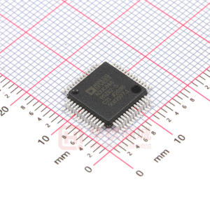
This document is an engineering report describing a 5 V, 30 W DC-DC converter utilizing the DPA424R. This document contains the power supply specification, schematic, bill of materials, transformer documentation, printed circuit layout, and performance data.
Figure 1 − EP-21 Populated Circuit Board (57.5 mm L x 43.6 mm W x 10.7 mm H).
Page 3 of 32
Power Integrations, Inc. Tel: +1 408 414 9660 Fax: +1 408 414 9760 www.powerint.com
�EPR-21 – 5 V, 30 W DC-DC Converter
19-Nov-02
2 Power Supply Specification
Description Input Input Voltage Input Voltage UV Turn-On Input Voltage UV Turn-Off Input Voltage OV Turn-Off Input Voltage OV Turn-On Output Output Voltage Output Ripple and Noise Output Current Line Regulation Load Regulation Transient Response Peak Deviation Transient Response Recovery Overload Current Total Output Power Continuous Output Power Efficiency Environmental Input-Output Isolation Voltage Ambient Temperature TAMB 1500 -40 75 VDC
o
Symbol VIN
Min 36 29 75 72
Typ 48
Max 72 36 90
Units VDC VDC VDC VDC VDC V mV A % % % of VOUT µs
Comment
See AN-31 See AN-31 See AN-31 See AN-31 ± 4% 20 MHz Bandwidth
VOUT VRIPPLE IOUT
4.8 0
5 65
5.2 100 6 ± 0.2 ± 0.5
3 200 IOUT_OL 8
50% to 75% load step, 100 mA/µs di/dt, 48 VDC input To 1% of final output voltage, 50% to 75% load step, 48 VDC input Unit enters auto-restart
A
POUT η 85
30
W %
Measured at POUT (30 W), 25 oC, 48 VDC Input
C
Dimensions
mm
Maximum continuous output power, 110 °C base plate temperature, natural convection, with Wakefield 628-65AB heat sink 57.5 mm L x 43.6 mm W x 10.7mm H (16.8 mm H including pins)
Power Integrations, Inc. Tel: +1 408 414 9660 Fax: +1 408 414 9760 www.powerint.com
Page 4 of 32
�19-Nov-02
EPR-21 – 5 V, 30 W DC-DC Converter
3 Schematic
Figure 2 − EP-21 Schematic.
Page 5 of 32
Power Integrations, Inc. Tel: +1 408 414 9660 Fax: +1 408 414 9760 www.powerint.com
�EPR-21 – 5 V, 30 W DC-DC Converter
19-Nov-02
4 Circuit Description
4.1 Primary Circuitry The schematic in Figure 2 shows a single-ended forward converter using the DPA424R. The circuit is designed for 36 V to 72 V input range and 5 V, 6 A output. C1 and L1 provide input filtering. C2 and C3 bypass the DC rail. The DC rail is applied to the primary winding of T1. The other side of the transformer primary is driven by the integrated MOSFET in U1. C8 reduces the amplitude of leakage spikes generated when the MOSFET in U1 switches off. VR1 clamps the U1 drain voltage to a safe value during fault conditions, but is inactive during normal operation. R1 is used to set the low line turn-on threshold to approximately 33 V, and also sets the overvoltage shutdown level to approximately 88 V. R3 sets the U1 current limit to approximately 85% of its nominal value, limiting the output power delivered during fault conditions. C5 bypasses the U1 CONTROL pin, and provides the peak current necessary for driving the DPA-Switch internal MOSFET. C6 has three functions. It provides the energy required by U1 during startup, sets the auto-restart frequency during fault conditions, and also reduces the gain of U1 as a function of frequency. R4 adds a zero to stabilize the power supply control loop. 4.2 Output Rectification The output of T1 is rectified and filtered by D2, L2, C10, and C11. This is the lowest cost rectification scheme. DPA-Switch is however fully compatible with simple self-driven synchronous rectification schemes as described in the DPA-Switch datasheet. C12 provides additional high frequency filtering, and is located close to the output terminals of the supply. C7 provides bypassing for high frequency common-mode noise coupled from the primary to the secondary of T1. R14 damps primary-to-secondary circulating current, which would otherwise appear imposed on the output ripple voltage. C9 and R5 provide some snubbing to D2, but their main purpose is to reset T1 during the U1 off time. During the U1 off time, magnetizing energy stored in the T1 primary during on time is coupled to the secondary, and charges C9. The voltage on C9 is a 1/2 sinusoid with a period determined by C9 and the reflected primary inductance of T1. C9 is sized such that the voltage generated during the off time is sufficient to reset T1 before the next switching cycle occurs. R5 provides damping for C9 to prevent high frequency ringing during switching transitions. U1 is powered during normal operation by an auxiliary flyback winding on L2. This winding delivers energy during the off time of U1, with an output voltage proportional to the supply output voltage. The turns ratio of L2 sets the output voltage of the auxiliary winding to approximately 12 V. D1 and C4 rectify and filter the auxiliary winding output.
Power Integrations, Inc. Tel: +1 408 414 9660 Fax: +1 408 414 9760 www.powerint.com
Page 6 of 32
�19-Nov-02
EPR-21 – 5 V, 30 W DC-DC Converter
R13 applies a small amount of preloading to the supply output to prevent the voltage at the auxiliary winding of L1 from collapsing at zero load. R13 is set to provide a minimum of 8 V at the cathode of D1 at zero load. 4.3 Output Feedback R10 and R11 divide down the supply output voltage and apply it to the reference pin of error amplifier U3. U3 drives optocoupler U2 through resistor R6 to provide feedback information to the CONTROL pin of U1. The optocoupler output also provides power to U1 during normal operating conditions. D3 and C13 apply drive to the optocoupler during supply startup to eliminate output voltage overshoot. D3 isolates C13 from the supply feedback loop after startup. R7 discharges C13 when the supply is off. R8 provides bias current to U3. C6, C14, C16, R4, R6, R9, and R12 all play a role in compensating the power supply control loop. C6 rolls off the gain of U1 at a relatively low frequency. R4 provides a zero to cancel the phase shift of C6. R6 sets the gain of the direct signal path from the supply output through U2 and U3. C14 and R9 roll off the gain of U3. R12 and C16 provide phase boost near the output filter (L2, C10-11) resonant frequency to improve phase margin and stability. 4.4 Construction The EP21 is constructed with surface mount components using an aluminum clad circuit board. The printed circuit board is an effective heat spreader, and allows attachment of a heat sink on the back of the board for operation at high ambient temperature. Tantalum and ceramic capacitors are used instead of conventional electrolytic capacitors to enable operation at extreme ambient temperatures.
Page 7 of 32
Power Integrations, Inc. Tel: +1 408 414 9660 Fax: +1 408 414 9760 www.powerint.com
�EPR-21 – 5 V, 30 W DC-DC Converter
19-Nov-02
5 PCB Layout
Figure 3 – EP-21 Printed Circuit Layout.
Power Integrations, Inc. Tel: +1 408 414 9660 Fax: +1 408 414 9760 www.powerint.com
Page 8 of 32
�19-Nov-02
EPR-21 – 5 V, 30 W DC-DC Converter
6 Bill Of Materials
EP-21 30 W 400 kHz DC-DC Bill Of Materials
Item 1 2 3 4 5 6 7 8 9 10 11 12 13 14 15 16 17 18 19 20 21 22 23 24 25 26 27 28 29 30 31 32 33 34 35 Qty 3 2 2 1 1 1 1 2 2 1 2 1 1 1 1 1 1 1 1 1 1 1 1 2 1 1 1 1 1 1 1 1 1 4 1 Reference C1-3 C4, 13 C5 C6 C7 C8 C9 C10, 11 C12, 14 C16 D1, 3 D2 L1 L2 R1 R2 R3 R4 R5 R6 R7 R8 R9 R10, 11 R12 R13 R14 R15 T1 U1 U2 U3 VR1 J1-1, 2 J2-1, 2 Description 1 µF, 100 V 1812 4.7 µF, 20 V B size 220 nF, 25 V 0805 68 µF, 10 V tantalum C size 1 nF, 1.5 kV 1808 47 pF, 200 V 0805 2.2 nF, 50 V 0805 100 µF, 10 V tantalum 1 µF, 10 V 0805 100 nF, 25 V 0805 250 mA, 100 V SOD-323 Schottky 25 A, 45 V 1 µH, 2.5 A 8 µH, 6 A PR1408 619 kΩ, 1% 0805 Not Placed 8.25 kΩ, 1% 0603 1 Ω, 5% 0603 1 Ω, 5% 1206 150 Ω, 5% 0603 10 kΩ, 5% 0603 1 kΩ, 5% 0603 220 Ω, 5% 0603 10 kΩ, 1% 0603 5.1 Ω, 5% 0603 160 Ω, 5% 1206 10 Ω, 5% 0603 Not Placed Transformer, Custom, PR1408 DPA424R Optocoupler, graded CTR Shunt Regulator SOT-23 TVS 150 V, 600 W Pin, Surface Mount, 0.060” x 0.580” EP-21 Aluminum Clad Printed Circuit Board Rev. E P/N THCR50E2A105ZT ECS-T1DY475R ECJ-2VB1C224K T491C476K010 1808SC102KAT1A ECJ-2VC2D470J ECJ-2VB1H222K TPSD10710R0100 ECJ-2YB1A105K ECJ-2YB1E104K BAV19W S MBRB2545CT SCD-0403-1R0M SIL6009 Rev. 6 ERJ-6ENF6193V ERJ-3EKF8251V ERJ-3GEYJ1R0V ERJ-8GEYJ1R0V ERJ-3GEYJ151V ERJ-3GEYJ103V ERJ-3GEYJ102V ERJ-3GEYJ221V ERJ-3EKF1002V ERJ-3GEYJ5R1V ERJ-8GEYJ161V ERJ-3GEYJ100V SIL6010 Rev. 8 PC357N1T LM431AIM3 SMBJ150A 1248-580-6 Manufacturer UCC Panasonic Panasonic Kemet AVX Panasonic Panasonic AVX Panasonic Panasonic Diodes, Inc. General Semiconductor Chilisin HiCal Panasonic Panasonic Panasonic Panasonic Panasonic Panasonic Panasonic Panasonic Panasonic Panasonic Panasonic Panasonic HiCal Power Integrations Sharp National Semiconductor General Semiconductor Zierick
Page 9 of 32
Power Integrations, Inc. Tel: +1 408 414 9660 Fax: +1 408 414 9760 www.powerint.com
�EPR-21 – 5 V, 30 W DC-DC Converter
19-Nov-02
7 Transformer Specification
1
W DG #3 7T #27 AW G
7, 8
W DG #2 4T 4 X #27 AW G
3
W DG #1 8T #27 AW G
5, 6
4 Figure 4 – EP-21 Transformer.
7.1
Electrical Specifications
Electrical Strength Creepage Primary Inductance Resonant Frequency Primary Leakage Inductance 1 s, from Pins 1-4 to Pins 5-8 Between Pins 1-4 and Pins 5-8 Pins 1-4, all other windings open, measured at 100 kHz, 400 mVRMS Pins 1-4, all other windings open Pins 1-4, with Pins 5-8 shorted, measured at 100 kHz, 400 mVRMS 1500 VDC N/A 450 µH, ±25% 3.8 MHz (min.) 1 µH (max.)
7.2
Materials
Item [1] [2] [3] [4] [5] Description Core: PR 14 X 8 Ungapped N87 Material Epcos P/N B65755-J-R87 Bobbin: 8 pin P1408 surface mount B&B B-096 or equivalent Magnet W ire: #27 AW G Double Coated Tape, Polyester, 3M #1298 or equiv. 4.5 mm wide Varnish
Power Integrations, Inc. Tel: +1 408 414 9660 Fax: +1 408 414 9760 www.powerint.com
Page 10 of 32
�19-Nov-02
EPR-21 – 5 V, 30 W DC-DC Converter
7.3
Transformer Build Diagram
1 Tape 3 Secondary
½ Primary 7, 8 5, 6
3 4 Figure 5 − EP-21 Transformer Build Diagram.
½ Primary
7.4
Transformer Construction
Start at Pin 4. W ind 8 turns of item [3] in 1 layer. Finish on Pin 3. Use one layer of item [4] for basic insulation. Start at Pins 5 and 6. W ind 4 quadrifilar turns of item [3]. Finish on Pins 7 and 8. Use one layer of item [4] for basic insulation. Start at Pin 3. W ind 7 turns of item [3] in 1 layer. Finish on Pin 1. W rap windings with 3 layers of tape item [4]. Assemble and secure core halves. Varnish impregnate item [5].
½ Primary Basic Insulation Secondary Winding Basic Insulation ½ Primary Outer Wrap Final Assembly
Page 11 of 32
Power Integrations, Inc. Tel: +1 408 414 9660 Fax: +1 408 414 9760 www.powerint.com
�EPR-21 – 5 V, 30 W DC-DC Converter
19-Nov-02
8 Inductor Specification
2
WDG #1 18 T #32 AWG WDG #2 7T 2 X #24 AWG
5, 6
1 Figure 6 – EP-21 Inductor, L2 Rev. 6.
7, 8
8.1
Electrical Specifications
Electrical Strength Creepage Inductance Resonant Frequency Primary Leakage Inductance 1 s, from Pins 1, 2 to Pins 5-8 Between Pins 1, 2 and Pins 5-8 Pins 5, 6 to 7, 8, all other windings open, measured at 100 kHz, 400 mVRMS 1500 VDC N/A 8 µH, ±10% N/A N/A
8.2
Materials
Item [1] [2] [3] [4] [5] [6] Description 2 Core: PR 14 X 8 Epcos N87, P/N B65755-J-R87 Gap for AL of 163 nH/T Bobbin: 8 pin P1408 surface mount B&B B-096 or equivalent Magnet W ire: #24 AW G Double Coated Magnet W ire: #32 AW G Double Coated Tape, Polyester, 3M #1298 or equiv. 4.5 mm wide Varnish
Power Integrations, Inc. Tel: +1 408 414 9660 Fax: +1 408 414 9760 www.powerint.com
Page 12 of 32
�19-Nov-02
EPR-21 – 5 V, 30 W DC-DC Converter
8.3
Inductor Build Diagram
Figure 7 – EP-21 Inductor Construction.
8.4
Inductor Construction
Start at Pin 1. W ind 18 turns of item [4] in approximately 1 layer. Finish on Pin 2. Use one layer of item [5] for basic insulation. Start at Pins 7 and 8. W ind 7 bifilar turns of item [3]. Finish on Pins 5 and 6. W rap windings with 3 layers of tape item [5]. Assemble and secure core halves. Varnish impregnate item [6].
Winding #1 Basic Insulation Winding #2 Outer Wrap Final Assembly
Page 13 of 32
Power Integrations, Inc. Tel: +1 408 414 9660 Fax: +1 408 414 9760 www.powerint.com
�EPR-21 – 5 V, 30 W DC-DC Converter
19-Nov-02
9 PIXls Design Spreadsheet
DCDC_DPAFwd_rev1.02_061802 Copyright Power Integrations Inc. 2002 OUTPUT VOLTAGE AND CURRENT VMAIN IMAIN VOUT2 IOUT2 POUT VBIAS 12.0 5 6 Volts Amps Volts Amps 30 Watts Volts INPUT INFO OUTPUT UNIT DPA_061802_R102xls: DPA-Switch Forward Transformer Design Spreadsheet EP21 DC-DC Converter Main output voltage Main output current Output2 voltage Output2 current Total output power DC bias voltage from output inductor winding
INPUT VOLTAGE AND UV/OV VMIN VMAX VUV OFF VUV ON VOV ON VOV OFF RL 36 72 min 30 30.0 32.2 74.8 max 33.1 DC volts 34.6 DC volts - DC volts 94.6 DC Volts 618.0 kOhm Minimum undervoltage On-Off threshold Maximum undervoltage Off-On threshold (turn-on) Minimum overvoltage Off-On threshold Maximum overvoltage On-Off threshold (turn-off) Line Sense resistor value (L-pin) - goal seek (VUV OFF) for std 1% resistor series DC volts DC volts Minimum DC input voltage Maximum DC input voltage
ENTER DPA-Switch VARIABLES DPA-Switch Chosen Device ILIMIT Frequency - (F)=400kHz, (L)=300kHz fS KI ILIMITEXT RX dpa424 DPA424 2.32 f 375000 1 2.32 Amps - kOhm 425000 400000 Hertz 2.68 16VDC Power 15.5 W Amps 36VDC 35W From DPA-Switch datasheet Full (F) frequency option - 400 kHz From DPA-Switch datasheet External limit reduction factor (KI=1.0 for default ILIMIT, KI