LYT3314-3328
LYTSwitch-3 Family
Single-Stage LED Driver IC with Combined PFC and
Constant Current Output for Outstanding TRIAC Dimming
in Isolated and Non-Isolated Topologies
Product Highlights
Combined Single-Stage PFC + Accurate CC Output
•
•
•
•
Less than ±3% CC regulation over line and load
Power Factor >0.9
Ensures monotonic VA reduction with TRIAC phase angle
Low THD, 15% typical for dimmable bulbs, as low as 7% in
optimized designs
L
T
LYTSwitch-3
N
Advanced Integrated TRIAC Dimmer Detection
•
•
•
•
•
•
Detects leading-edge and trailing-edge TRIAC dimmers
High-efficiency mode when no dimmer is present
Selectable dimming profile increases design flexibility
Fast turn-on ( VFB > VFB(SK)
(MOSFET not switching)
Min
Typ
Max
Units
0.8
1.0
mA
LYT3314
0.9
1.2
LYT3324
1.0
1.3
LYT3315
1.0
1.3
LYT3325
1.1
1.4
LYT3316
1.1
1.4
LYT3326
1.1
1.4
LYT3318
1.2
1.5
LYT3328
1.3
1.6
Control Functions (cont.)
DRAIN Supply Current
IS2
MOSFET Switching
at fMAX
BYPASS Pin
Charge Current
ICH1
VBP = 0 V, TJ = 25 °C
BYPASS Pin
Charge Current
ICH2
VBP = 4 V, TJ = 25 °C
BYPASS Pin Voltage
VBP
BYPASS Pin
Shunt Voltage
BYPASS Pin Power-Up
Reset Threshold Voltage
VSHUNT
LYT33x4
-8.5
-7.5
-6.0
LYT33x5-8
-11.5
-9.5
-7.5
LYT33x4
-6.5
-5.2
-4.0
LYT33x5-8
-8.8
-6.8
-4.8
4.75
5.00
5.25
5.1
5.30
5.5
4.4
4.6
4.8
IBP = 5 mA
VBP(RESET)
mA
mA
mA
V
V
Circuit Protection
Current Limit
ILIMIT
di/dt = 662 mA/ms
TJ = 25 °C
LYT33x4
843
907
970
di/dt = 974 mA/ms
TJ = 25 °C
LYT33x5
1232
1325
1418
di/dt = 1403 mA/ms
TJ = 25 °C
LYT33x6
1767
1900
2033
di/dt = 2239 mA/ms
TJ = 25 °C
LYT33x8
2860
3075
3290
130
165
ns
160
ns
mA
Leading Edge
Blanking Time
tLEB
TJ = 25 °C
Current Limit Delay
TILD
TJ = 25 °C, See Note A
Thermal Foldback
Temperature
TFB
See Note A
138
142
146
°C
Thermal Shutdown
Temperature
TSD
See Note A
155
160
165
°C
Thermal Shutdown
Hysteresis
TSD(H)
See Note A
75
TON(SOA)
TJ = 25 °C
610
SOA Switch ON-Time
°C
690
ns
11
www.power.com
Rev. D 04/16
�LYT3314-3328
Symbol
Conditions
SOURCE = 0 V
TJ = -40 °C to +125 °C
(Unless Otherwise Specified)
Min
Typ
Max
Units
Auto-Restart Current
Threshold for Output
Undervoltage
IOUV
TJ = 25 °C
40
52
58
mA
Current Threshold for
Input Overvoltage
ILOV+
116
120
124
Latch-Off Current
Threshold for Output
Overvoltage
IOOV
TJ = 25 °C
127
134
144
mA
VL
IL = 100 mA, TJ = 25 °C
2.05
2.25
2.45
V
VOC
IOC = 100 mA
TJ = 25 °C
2.05
2.25
2.45
V
TJ = 25 °C
5.40
6.20
TJ = 100 °Cdrdxd
8.40
9.70
TJ = 25 °C
3.80
4.35
TJ = 100 °C
5.70
6.55
TJ = 25 °C
2.75
3.15
TJ = 100 °C
4.25
4.90
TJ = 25 °C
1.75
2.00
TJ = 100 °C
2.70
3.10
Parameter
Circuit Protection (cont.)
LINE-SENSE Pin Voltage
Threshold
TJ = 25 °C
Hysteresis
5
mA
Output
OUTPUT COMPENSATION
Pin Voltage
LYT33x4
ID = 150 mA
ON-State
Resistance
LYT33x5
ID = 200 mA
RDS(ON)
LYT33x6
ID = 300 mA
LYT33x8
ID = 500 mA
OFF-State Leakage
IDSS
Breakdown Voltage
BVDSS
VBP = 5.3 V, VFB > VFB(SK) , VDS = 580 V
TJ = 125 °C
VBP = 5.3 V, VFB >
VFB(SK)
TJ = 25 °C
200
LYT331x
650
LYT332x
725
W
mA
V
NOTES:
A. Guaranteed by design.
12
Rev. D 04/16
www.power.com
�LYT3314-3328
150
125
Scaling Factors:
LYT3314 1.0
LYT3315 1.4
LYT3316 2.05
LYT3318 3.35
100
75
50
725 V
650 V
25
0
0
100
200
300
400
500
600
1.2
725 V
650 V
1
0.8
0.6
0.4
0.2
0
0
100 200 300 400 500 600 700 800
DRAIN Voltage (V)
DRAIN Voltage (V)
Figure 11. Power vs. Drain Voltage.
Figure 12. Maximum Allowable Drain Current vs. Drain Voltage.
1.2
1
0.8
Scaling Factors:
LYT3324 1.0
LYT3325 1.4
LYT3326 2.05
LYT3328 3.35
0.4
0.2
0
0
2
4
6
8
PI-7783-110915
1.4
2
1.8
DRAIN Current (A)
1.6
DRAIN Current (A)
2.2
PI-7782-110915
1.8
0.6
PI-7758-101615
Scaling Factors:
LYT3324 1.0
LYT3325 1.4
LYT3326 2.05
LYT3328 3.35
175
Power (mW)
PI-7781-110915
200
DRAIN Current
(Normalized to Absolute Max Rating)
Typical Performance Curves
725 V
25 °C
725 V
125 °C
1.6
1.4
1.2
1
0.8
0.6
Scaling Factors:
LYT3314 1.0
LYT3315 1.4
LYT3316 2.05
LYT3318 3.35
0.4
0.2
0
10 12 14 16 18 20
0
2
DRAIN Voltage (V)
4
6
8
650 V
25 °C
650 V
125 °C
10 12 14 16 18 20
DRAIN Voltage (V)
Figure 14. Drain Current vs. Drain Voltage.
DRAIN Capacitance (pF)
10000
725 V
650 V
Scaling Factors:
LYT3324 1.0
LYT3325 1.4
LYT3326 2.05
LYT3328 3.35
1000
PI-7784-110915
Figure 13. Drain Current vs. Drain Voltage.
Scaling Factors:
LYT3314 1.0
LYT3315 1.4
LYT3316 2.05
LYT3318 3.35
100
1
0
100
200
300
400
500
600
DRAIN Voltage (V)
Figure 15. Drain Capacitance vs. DRAIN Pin Voltage.
13
www.power.com
Rev. D 04/16
�LYT3314-3328
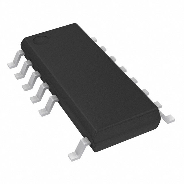
SO-16B
3
4
0.019 [0.48] 14X
0.013 [0.33]
0.010 [0.25] M C A B
0.050 [1.27]
8 Lead Tips
16
2X
9
0.044 [1.10] Ref.
0.005 [0.13] C
0.004 [0.10] C B
H
0.010 [0.25]
0.153 [3.90]
0.239 [6.07]
2
Gauge Plane
Seating Plane
1
B
0.005 [0.13] C
8
Pin #1 I.D.
(Laser Marked)
0.135 [3.43]
Ref.
A
0.390 [9.91]
8º
0º
C
6 Lead Tips
0.032 [0.81]
0.022 [0.56]
2
0.004 [0.10] C A 2X
DETAIL A
TOP VIEW
0.066 [1.69]
0.057 [1.46]
0.054 [1.38] Ref.
Seating
Plane
C
0.010 [0.25]
0.004 [0.10]
Detail A
0.010 [0.25]
0.004 [0.10]
0.004 [0.10] C
14 Leads
SIDE VIEW
Notes:
1. Dimensioning and tolerancing per
ASME Y14.5M-1994.
2. Dimensions noted are determined at the
outermost extremes of the plastic body exclusive
of mold flash, tie bar burrs, gate burrs, and
inter-lead flash, but including any mismatch
between the top and bottom of the plastic body.
Maximum mold protrusion is 0.25 mm per side.
3. Dimensions noted are inclusive of plating
thickness.
4. Does not include inter-lead flash or protrusions.
END VIEW
5. Dimensions in Inches [mm].
6. Datums A and B to be determined in Datum H.
7. JEDEC reference: MS − 012.
PI-7473-061515
POD-SO-16B Rev A
14
Rev. D 04/16
www.power.com
�LYT3314-3328
PACKAGE MARKING
SO-16B
B
A
A.
B.
C.
D.
1545
LYT33x8D
M4P167A
C
D
Power Integrations Registered Trademark
Assembly Date Code (last two digits of year followed by 2-digit work week)
Product Identification (Part #/Package Type)
Lot Identification Code
PI-7801-111915
15
www.power.com
Rev. D 04/16
�LYT3314-3328
MSL Table
Part Number
MSL Rating
LYT33x4
3
LYT33x5
3
LYT33x6
3
LYT33x8
3
ESD and Latch-Up Table
Test
Conditions
Results
Latch-up at 125 °C
JESD78D
Human Body Model ESD
JESD22-A114F
> ±2000 V on all pins
Machine Model ESD
JESD22-A115CA
> ±200 V on all pins
> ±100 mA or > 2.5 kV (max) on all pins
Part Ordering Information
• LYTSwitch-3 Product Family
• Series Number
• Package Identifier
D
SO-16B
• Tape & Reel and Other Options
Blank
LYT 33x4 D - TL
TL
Tube of 50 pcs.
Tape & Reel, 2500 pcs min/mult.
16
Rev. D 04/16
www.power.com
�LYT3314-3328
Notes
17
www.power.com
Rev. D 04/16
�Revision Notes
Date
A
Code S Release.
B
Added Block diagram and Typical Performance Curves.
09/15
11/09/15
C
Code A Release.
02/16
D
Corrected IS2 parameter. Added VOC and VL parameters.
03/16
D
TON(MAX) parameter errors fixed.
04/01/16
For the latest updates, visit our website: www.power.com
Power Integrations reserves the right to make changes to its products at any time to improve reliability or manufacturability. Power Integrations
does not assume any liability arising from the use of any device or circuit described herein. POWER INTEGRATIONS MAKES NO WARRANTY
HEREIN AND SPECIFICALLY DISCLAIMS ALL WARRANTIES INCLUDING, WITHOUT LIMITATION, THE IMPLIED WARRANTIES OF MERCHANTABILITY,
FITNESS FOR A PARTICULAR PURPOSE, AND NON-INFRINGEMENT OF THIRD PARTY RIGHTS.
Patent Information
The products and applications illustrated herein (including transformer construction and circuits external to the products) may be covered by one
or more U.S. and foreign patents, or potentially by pending U.S. and foreign patent applications assigned to Power Integrations. A complete list of
Power Integrations patents may be found at www.power.com. Power Integrations grants its customers a license under certain patent rights as set
forth at http://www.power.com/ip.htm.
Life Support Policy
POWER INTEGRATIONS PRODUCTS ARE NOT AUTHORIZED FOR USE AS CRITICAL COMPONENTS IN LIFE SUPPORT DEVICES OR SYSTEMS
WITHOUT THE EXPRESS WRITTEN APPROVAL OF THE PRESIDENT OF POWER INTEGRATIONS. As used herein:
1. A Life support device or system is one which, (i) is intended for surgical implant into the body, or (ii) supports or sustains life, and (iii) whose
failure to perform, when properly used in accordance with instructions for use, can be reasonably expected to result in significant injury or
death to the user.
2. A critical component is any component of a life support device or system whose failure to perform can be reasonably expected to cause the
failure of the life support device or system, or to affect its safety or effectiveness.
The PI logo, TOPSwitch, TinySwitch, LinkSwitch, LYTSwitch, InnoSwitch, DPA-Switch, PeakSwitch, CAPZero, SENZero, LinkZero, HiperPFS,
HiperTFS, HiperLCS, Qspeed, EcoSmart, Clampless, E-Shield, Filterfuse, FluxLink, StakFET, PI Expert and PI FACTS are trademarks of Power
Integrations, Inc. Other trademarks are property of their respective companies. ©2016, Power Integrations, Inc.
Power Integrations Worldwide Sales Support Locations
World Headquarters
5245 Hellyer Avenue
San Jose, CA 95138, USA.
Main: +1-408-414-9200
Customer Service:
Phone: +1-408-414-9665
Fax: +1-408-414-9765
e-mail: usasales@power.com
China (Shanghai)
Rm 2410, Charity Plaza, No. 88
North Caoxi Road
Shanghai, PRC 200030
Phone: +86-21-6354-6323
Fax: +86-21-6354-6325
e-mail: chinasales@power.com
China (Shenzhen)
17/F, Hivac Building, No. 2, Keji Nan
8th Road, Nanshan District,
Shenzhen, China, 518057
Phone: +86-755-8672-8689
Fax: +86-755-8672-8690
e-mail: chinasales@power.com
Germany
Lindwurmstrasse 114
80337 Munich
Germany
Phone: +49-895-527-39110
Fax: +49-895-527-39200
e-mail: eurosales@power.com
India
#1, 14th Main Road
Vasanthanagar
Bangalore-560052 India
Phone: +91-80-4113-8020
Fax: +91-80-4113-8023
e-mail: indiasales@power.com
Italy
Via Milanese 20, 3rd. Fl.
20099 Sesto San Giovanni (MI)
Italy
Phone: +39-024-550-8701
Fax: +39-028-928-6009
e-mail: eurosales@power.com
Japan
Kosei Dai-3 Bldg.
2-12-11, Shin-Yokohama,
Kohoku-ku
Yokohama-shi, Kanagawa
222-0033 Japan
Phone: +81-45-471-1021
Fax: +81-45-471-3717
e-mail: japansales@power.com
Taiwan
5F, No. 318, Nei Hu Rd., Sec. 1
Nei Hu Dist.
Taipei 11493, Taiwan R.O.C.
Phone: +886-2-2659-4570
Fax: +886-2-2659-4550
e-mail: taiwansales@power.com
UK
Cambridge Semiconductor,
Korea
a Power Integrations company
RM 602, 6FL
Westbrook Centre, Block 5, 2nd Floor
Korea City Air Terminal B/D, 159-6 Milton Road
Samsung-Dong, Kangnam-Gu,
Cambridge CB4 1YG
Seoul, 135-728, Korea
Phone: +44 (0) 1223-446483
Phone: +82-2-2016-6610
e-mail: eurosales@power.com
Fax: +82-2-2016-6630
e-mail: koreasales@power.com
Singapore
51 Newton Road
#19-01/05 Goldhill Plaza
Singapore, 308900
Phone: +65-6358-2160
Fax: +65-6358-2015
e-mail: singaporesales@power.com
�