Title
Reference Design Report for a High
Performance 347 W PFC Stage Using
HiperPFS™ PFS714EG
Specification
90 VAC – 264 VAC Input; 380 VDC Output
Application
PFC Front End Stage
Author
Applications Engineering Department
Document
Number
RDR-236
Date
November 18, 2010
Revision
1.1
Summary and Features
Low component count, high performance PFC
EN61000–3–2 Class–D compliance
High PFC efficiency enables 80+ PC Main design
Frequency sliding maintains high efficiency across load range
Feed forward line sense gain - maintains relatively constant loop gain over entire
operating voltage range
Excellent transient load response
Power Integration eSIP low-profile, thermal resistance package
PATENT INFORMATION
The products and applications illustrated herein (including transformer construction and circuits external to the products) may be covered
by one or more U.S. and foreign patents, or potentially by pending U.S. and foreign patent applications assigned to Power Integrations. A
complete list of Power Integrations' patents may be found at www.powerint.com. Power Integrations grants its customers a license under
certain patent rights as set forth at .
.
Power Integrations
5245 Hellyer Avenue, San Jose, CA 95138 USA.
Tel: +1 408 414 9200 Fax: +1 408 414 9201
www.powerint.com
�RDR-236 347 W PFC Using PFS714EG
18-Nov-10
Table of Contents
1
2
3
4
Introduction.................................................................................................................4
Power Supply Specification ........................................................................................5
Schematic...................................................................................................................6
Circuit Description ......................................................................................................7
4.1
Input EMI Filter and Rectifier ...............................................................................7
4.2
PFS714EG Boost Converter ...............................................................................7
4.3
Bias Supply Regulator .........................................................................................7
4.4
Input Feed Forward Sense Circuit.......................................................................7
4.5
Output Feedback.................................................................................................8
5 PCB Layout ................................................................................................................9
6 Bill of Materials .........................................................................................................10
7 Inductor Specification ...............................................................................................12
7.1
Electrical Diagram .............................................................................................12
7.2
Electrical Specifications.....................................................................................12
7.3
Materials............................................................................................................12
7.4
Inductor Winding Instruction ..............................................................................13
8 Performance Data ....................................................................................................16
8.1
Efficiency (RT1 and RT2 Shorted).....................................................................16
8.2
Input Power Factor ............................................................................................17
8.3
Regulation .........................................................................................................18
8.3.1
Load ...........................................................................................................18
8.3.2
Line ............................................................................................................19
8.4
Input Current Harmonic Distortion (IEC 61000–3–2 Class–D) ..........................20
8.4.1
50% Load at Output ...................................................................................20
8.4.2
100% Load at Output .................................................................................21
9 Thermal Performance...............................................................................................22
10
Waveforms............................................................................................................24
10.1 Input Current at 115 VAC and 60 Hz .................................................................24
10.2 Input Current at 230 VAC and 50 Hz .................................................................24
10.3 Start-up at 90 VAC and 60 Hz ...........................................................................25
10.4 Start-up at 115 VAC and 60 Hz .........................................................................25
10.5 Start-up at 230 VAC and 50 Hz .........................................................................26
10.6 Start-up at 264 VAC and 50 Hz .........................................................................26
10.7 Load Transient Response (90 VAC, 60 Hz) ......................................................27
10.8 Load Transient Response (115 VAC, 60 Hz) ....................................................28
10.9 Load Transient Response (230 VAC, 50 Hz) ....................................................28
10.10
Load Transient Response (264 VAC, 50 Hz).................................................29
10.11
1000 ms Line Dropout (115 VAC / 60 Hz and 230 VAC / 50 Hz) ...................29
10.11.1
50% Load at Output................................................................................29
10.11.2
Full Load at Output .................................................................................30
10.12
One Cycle Line Dropout (115 VAC / 60 Hz and 230 VAC / 50 Hz) ................30
10.12.1
Full Load at Output .................................................................................30
10.13
Line Sag (115 VAC – 85 VAC – 115 VAC, 60 Hz) .........................................31
10.14
Line Surge (132 VAC – 147 VAC – 132 VAC, 60 Hz)....................................31
10.15
Line Sag (230 VAC – 170 VAC – 230 VAC, 50 Hz) .......................................32
Power Integrations, Inc.
Tel: +1 408 414 9200 Fax: +1 408 414 9201
www.powerint.com
Page 2 of 56
�18-Nov-10
RDR-236 347 W PFC Using PFS714EG
10.16
Line Surge (264 VAC – 293 VAC – 264 VAC, 50 Hz) ....................................32
10.17
Brown–In and Brown–Out at 6 V / Minute Rate .............................................33
10.18
Drain Voltage and Current .............................................................................34
10.18.1
Dain Voltage and Current at 115 VAC Input and Full Load.....................34
10.18.2
Drain Voltage and Current at 230 VAC Input and Full Load....................35
10.19
Output Ripple Measurements ........................................................................36
10.19.1
Ripple Measurement Technique .............................................................36
10.19.2
Measurement Results .............................................................................37
11
Gain–Phase Measurement Procedure and Results ..............................................39
12
Line Surge Test .....................................................................................................41
13
EMI Scans.............................................................................................................42
13.1 EMI Test Set-up.................................................................................................42
13.2 EMI Scans .........................................................................................................43
14
Appendix A – Efficiency with Other Diode and Core Materials..............................45
15
Appendix B – Test Set-up for Efficiency Measurement .........................................50
16
Appendix C – Inductor Current Measurement Set-up............................................52
17 Revision History ..........................................................................................................55
Important Note:
Although this board is designed to satisfy safety isolation requirements, the engineering
prototype has not been agency approved. Therefore, all testing should be performed
using an isolation transformer to provide the AC input to the prototype board.
Page 3 of 56
Power Integrations
Tel: +1 408 414 9200 Fax: +1 408 414 9201
www.powerint.com
�RDR-236 347 W PFC Using PFS714EG
18-Nov-10
1 Introduction
This document is an engineering report describing a PFC power supply utilizing a
HiperPFS PFS714EG integrated PFC controller. This power supply is intended as a
general purpose evaluation platform that operates from universal input and provides a
regulated 380 V DC output voltage and a continuous output power of 347 W.
This power supply can deliver the rated power at 110 VAC or higher at a room
temperature of 25 ºC. For operation at higher temperatures or lower input voltages, use
of forced air cooling is recommended.
The document contains the power supply specification, schematic, bill of materials,
inductor documentation, printed circuit layout, and performance data.
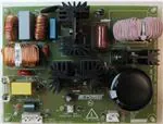
Figure 1 – Populated Circuit Board Photograph.
.
Power Integrations, Inc.
Tel: +1 408 414 9200 Fax: +1 408 414 9201
www.powerint.com
Page 4 of 56
�18-Nov-10
RDR-236 347 W PFC Using PFS714EG
2 Power Supply Specification
The table below represents the minimum acceptable performance of the design. Actual
performance is listed in the results section.
Description
Input
Voltage
Frequency
Output
Output Voltage
Output Ripple Voltage p-p
Output Current
Total Output Power
Continuous Output Power
Efficiency
Full Load
Minimum efficiency at 20, 50
and 100 % of POUT
Symbol
Min
Typ
Max
Units
Comment
VIN
fLINE
90
47
264
64
VAC
Hz
3 Wire
50/60
VOUT
VRIPPLE
IOUT
370
380
390
30
0.913
V
V
A
347
W
POUT
20 MHz bandwidth
94
%
Measured at POUT 25 C
80+
94
%
Measured at 115 VAC Input
kV
kV
1.2/50 s surge, IEC 1000-4-5,
Series Impedance:
Differential Mode: 2
Common Mode: 12
o
Environmental
Line Surge
Differential Mode (L1-L2)
Common mode (L1/L2-PE)
1
2
Ambient Temperature
TAMB
0
50
Auxiliary Supply Input
Auxiliary Supply
VAUX
15
24
Page 5 of 56
C
Forced convection required at TAMB
>25 ºC and/or VIN
很抱歉,暂时无法提供与“RDK-236”相匹配的价格&库存,您可以联系我们找货
免费人工找货