Features
Regulated
Converter
•
•
•
•
•
•
2:1 input voltage range
1.6kVDC isolation
UL certified
Efficiency up to 89%
Six-sided continuous shield
No minimum load required
Description
The RP20-F series DC/DC converters are certified to UL 60950-1 and to cUL 60950-1. This makes
them ideal for all telecom and industrial applications where approved safety standards are required. The
industry standard 2” x 1” package meets military standards for thermal shock and vibration tolerance.
Selection Guide
Part Number
Input
Output
Output
Input (1) Efficiency (1) Max. Capacitive
Voltage Range Voltage
Current
Current
typ.
Load (2)
[VDC] [VDC] [mA] [mA] [%]
[µF]
RP20-123.3SF (3,4) 9-18 3.3 5000 1618 85
13000
RP20-1205SF (3,4)
9-18
5
4000
1916
87
6800
RP20-1212SF (3,4) 9-18 12 1670 1942 86
2200
RP20-1215SF (3,4) 9-18 15 1330 1933 86
755
RP20-243.3SF (3,4) 18-36 3.3 5000 799 86
13000
RP20-2405SF (3,4) 18-36 5 4000 936 89
6800
RP20-2412SF (3,4)
18-36
12
1670
960
87
2200
RP20-2415SF (3,4) 18-36 15 1330 955 87
755
RP20-483.3SF (3,4) 36-75 3.3 5000 395 87
13000
RP20-4805SF (3,4) 36-75 5 4000 468 89
6800
RP20-4812SF (3,4) 36-75 12 1670 474 88
2200
RP20-4815SF (3,4) 36-75 15 1330 477 87
755
RP20-1212DF (3,4) 9-18 ±12 ±833 1937 86
±680
RP20-1215DF (3,4) 9-18 ±15 ±667 1938 86
±450
RP20-2412DF (3,4) 18-36 ±12 ±833 957 87
±680
RP20-2415DF (3,4) 18-36 ±15 ±667 947 88
±450
RP20-4812DF (3,4) 36-75 ±12 ±833 473 88
±680
RP20-4815DF (3,4) 36-75 ±15 ±667 473 88
±450
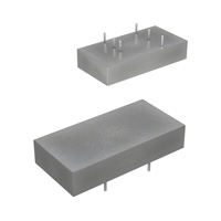
DC/DC Converter
RP20-F
20 Watt
2“ x 1“
Single and Dual
Output
E196683
UL60950-1 certified
Notes:
Note1: Maximum values at nominal input voltage and full load
Note2: Max. Cap load is tested at minimum input and constant resistive load
Model Numbering
RP20-__ __ _F/_-_
nom. Input Voltage
Output Voltage
“Package (4)”
“CTRL Logic (3)”
Single or Dual
Notes:
Note3: no suffix for CTRL function with positive logic (1=ON, 0=OFF)
add suffix “N” for CTRL function with negative logic (0=ON, 1=OFF)
Note4: add suffix “-HC” for premounted Heat-sink with clips
Ordering Examples
RP20-2405SF = 24V input, 5V output, single, positive Logic CTRL pin
RP20-4812DF/N-HC = 48V input, ±12V output, dual, negative Logic CTRL pin, Heat-sink premounted
www.recom-power.com
REV.: 2/2019
PD-1
�RP20-F
DC/DC Converter
Series
Specifications (measured @ Ta= 25°C, nom. Vin, full load unless otherwise stated)
BASIC CHARACTERISTICS
Parameter
Input Filter
Condition
Min.
Typ.
nom. Vin = 12VDC
nom. Vin = 24VDC
nom. Vin = 48VDC
9VDC
18VDC
36VDC
12VDC
24VDC
48VDC
Max.
LC-Type
18VDC
36VDC
75VDC
36VDC
50VDC
100VDC
(5)
Input Voltage Range
nom. Vin = 12VDC
nom. Vin = 24VDC
nom. Vin = 48VDC
refer to „OUTPUT VOLTAGE TRIMMING“
Input Surge Voltage
100ms max.
Output Voltage Trimming
-10%
+10%
20mAp-p
Input Reflected Ripple Current (6)
Single
Dual
Minimum Load (7)
0%
10%
Power up
ON/OFF CTRL
Start-up Time
10ms
10ms
Positive Logic
DC-DC ON
DC-DC OFF
Negative Logic
DC-DC ON
DC-DC OFF
ON/OFF CTRL (8)
Input Current of CTRL pin
DC-DC ON
Standby Current
DC-DC OFF
Open or 3.0VDC < VCTRL< 12VDC
Short or 0VDC < VCTRL< 1.2VDC
Short or 0VDC < VCTRL< 1.2VDC
Open or 3.0VDC < VCTRL< 12VDC
-0.5mA
+0.5mA
2.5mA
Internal Operating Frequency
450kHz
measured at 20MHz BW
with a 0.1µF/50V MLCC
Ripple and Noise
500kHz
3.3Vout
5Vout, 12Vout, 15Vout
60mVp-p
75mVp-p
±12Vout, ±15Vout
100mVp-p
550kHz
Notes:
Note5: An external filter capacitor is required for normal operation. The capacitor should be capable of handling 1A
ripple current for 48V/24V models. RECOM suggest: Nippon chemi-con KY series, 220μF/100V, ESR 90m Ω
Note6: Simulated source impedance of 12μH. 12μH inductor in series with +Vin
Note7: The RP15-F series requires a minimum of 10% loading on the output to maintain specified regulation. Operation
under no-load condition will not damage these devices, however they may not meet all listed specification
Note8: The ON/OFF control function can be p ositive or negative logic. The pin voltage is referenced to -Vin pin
RP20-1205SF
Efficiency vs. Input Voltage full load
Efficiency vs. Output Current
95
92
90
90
Efficiency [%]
Efficiency [%]
85
80
75
70
65
60
55
9Vin
12Vin
18Vin
50
45
40
10
20
30
40
50
60
70
80
90
88
86
84
82
80
100
9
10
11
12
13
14
15
16
17
18
Input Voltage [VDC]
Output Current [%]
continued on next page
www.recom-power.com
REV.: 2/2019
PD-2
�RP20-F
DC/DC Converter
Series
Specifications (measured @ Ta= 25°C, nom. Vin, full load unless otherwise stated)
RP20-2405SF
Efficiency vs. Output Current
95
Efficiency vs. Input Voltage full load
92
90
90
80
Efficiency [%]
Efficiency [%]
85
75
70
65
60
55
18Vin
24Vin
36Vin
50
45
40
10
20
30
40
50
60
70
80
90
88
86
84
82
80
100
18
20
22
Output Current [%]
24
26
28
30
32
34
36
Input Voltage [VDC]
RP20-4805SF
Efficiency vs. Output Current
95
Efficiency vs. Input Voltage full load
92
90
90
80
Efficiency [%]
Efficiency [%]
85
75
70
65
60
55
36Vin
48Vin
75Vin
50
45
40
10
20
30
40
50
60
70
80
90
88
86
84
82
80
36
100
40
44
48
52
56
60
64
68
72
75
Input Voltage [VDC]
Output Current [%]
OUTPUT VOLTAGE TRIMMING
Output Voltage Trimming
Single output Powerline converters offer the feature of trimming the output voltage over a certain range around the nominal value by using external
trim resistors. No general equation can be given for calculating the trim resistors, but the following trimtables give typical values for choosing these
trimming resistors. If voltages between the given trim points are required, extrapolate between the two nearest given values to work out the resistor
required or use a variable resistor to set the output voltage. Output can be externally trimmed by using the method shown below.
-Vout
Trim up
Trim down
Trim
RD
RU
Trim
+Vout
continued on next page
www.recom-power.com
REV.: 2/2019
PD-3
�RP20-F
DC/DC Converter
Series
Specifications (measured @ Ta= 25°C, nom. Vin, full load unless otherwise stated)
RP20-xx3.3SF
Trim up
1
2
3
4
5
6
7
8
9
10
[%]
Vout =
3.333
3.366
3.399
3.432
3.465
3.498
3.531
3.564
3.597
3.63
[VDC]
RU =
57.93
26.16
15.58
10.28
7.11
4.99
3.48
2.34
1.46
0.75
[kW]
1
2
3
4
5
6
7
8
9
10
[%]
Vout =
3.267
3.234
3.201
3.168
3.135
3.102
3.069
3.036
3.003
2.97
[VDC]
RD =
69.47
31.23
18.49
12.12
8.29
5.74
3.92
2.56
1.50
0.65
[kW]
2
3
4
5
6
7
8
9
10
[%]
Trim down
RP20-xx05SF
Trim up
1
Vout =
5.05
5.01
5.15
5.20
5.25
5.30
5.35
5.4
5.45
5.50
[VDC]
RU =
36.57
16.58
9.92
6.58
4.59
3.25
2.30
1.59
1.03
0.59
[kW]
1
2
3
4
5
6
7
8
9
10
[%]
Trim down
Vout =
4.95
4.90
4.85
4.80
4.75
4.70
4.65
4.60
4.55
4.50
[VDC]
RD =
45.53
20.61
12.31
8.15
5.66
4.00
2.81
1.92
1.23
0.68
[kW]
RP20-xx12SF
Trim up
1
2
3
4
5
6
7
8
9
10
[%]
Vout =
12.12
12.24
12.36
12.48
12.60
12.72
12.84
12.96
13.08
13.20
[VDC]
RU =
367.91
165.95
98.64
64.98
44.78
31.32
21.70
14.49
8.88
4.39
[kW]
1
2
3
4
5
6
7
8
9
10
[%]
Vout =
11.88
11.76
11.64
11.52
11.40
11.28
11.16
11.04
10.92
10.8
[VDC]
RD =
460.99
207.95
123.60
81.42
56.12
39.25
27.20
18.16
11.13
5.51
[kW]
Trim down
RP20-xx15SF
Trim up
1
2
3
4
5
6
7
8
9
10
[%]
Vout =
15.15
15.3
15.45
15.60
15.75
15.90
16.05
16.20
16.35
16.50
[VDC]
RU =
404.18
180.59
106.06
68.80
46.44
31.53
20.88
12.90
6.69
1.72
[kW]
1
2
3
4
5
6
7
8
9
10
[%]
Vout =
14.85
14.70
14.55
14.40
14.25
14.10
13.95
13.80
13.65
13.50
[VDC]
RD =
499.82
223.41
131.27
85.20
57.56
39.14
25.97
16.10
8.42
2.282
[kW]
Trim down
REGULATIONS
Parameter
Condition
Output Accuracy
Line Regulation
Value
±1.0%
low line to high line, full load
±0.2%
Load Regulation
0% to 100% load
±0.5%
Cross Regulation
asymmetrical 25%100% load
±5.0%
Transient Response Recovery Time
www.recom-power.com
25% load step change
REV.: 2/2019
250μs typ.
PD-4
�RP20-F
DC/DC Converter
Series
Specifications (measured @ Ta= 25°C, nom. Vin, full load unless otherwise stated)
PROTECTIONS
Parameter
Condition
Value
Short Circuit Protection (SCP)
continuous, automatic recovery
Over Voltage Protection (OVP)
zener diode clamp
Over Load Protection (OLP)
3.9VDC
6.2VDC
15VDC
18VDC
3.3Vout
5Vout
12Vout
15Vout
% of Iout rated
Isolation Voltage (9)
I/P to O/P
I/P to O/P to case
Isolation Resistance
Viso= 500VDC
150% typ.
1.6kVDC/ 1 minute
1.6kVDC/ 1 minute
1GΩ min.
Isolation Capacitance
1000pF max.
Notes:
Note9: For repeat Hi-Pot testing, reduce the time and/or the test voltage
Note10: This power module is not internally fused. An input line fuse must always be used
ENVIRONMENTAL
Parameter
Condition
Value
without derating
with derating
Operating Temperature Range
-40°C to +70°C
-40°C to +100°C
Maximum Case Temperature
+100°C
Temperature Coefficient
±0.02%/K max.
@ natural convection
0.1m/s
Thermal Impedance
without heat-sink
with heat-sink
12K/W
10K/W
Operating Altitude
2000m
Operating Humidity
non-condensing
5% - 95% RH
Pollution Degree
PD2
Thermal Shock
according to MIL-STD-810F
Vibration
according to MIL-STD-810F
MIL-HDBK-217F, G.B.
Bellcore TR-NWT-000332 (11)
MTBF
1583 x 103 hours
1791 x 10³ hours
Derating Graph (12)
RP20-4805SF-HC
100
100
80
80
Output Power [%]
Output Power [%]
RP20-4805SF
60
40
20
0
-40
-20
0
20
40
60
70
80
60
40
20
0
-40
100 120
Ambient Temperature [°C]
-20
0
20
40
60
80
75
100 120
Ambient Temperature [°C]
Notes:
Note11: BELLCORE TR-NWT-000332. Case l: 50% Stress, Temperature at 40°C (Ground fixed and controlled environment)
Note12: Derating graphs are valid only for the shown part numbers. If you need detailed derating-information about a part-number
not shown here please contact RECOM Techsupport for detailed information
www.recom-power.com
REV.: 2/2019
PD-5
�RP20-F
DC/DC Converter
Series
Specifications (measured @ Ta= 25°C, nom. Vin, full load unless otherwise stated)
SAFETY AND CERTIFICATIONS
Certificate Type (Safety)
Condition
Information Technology Equipment, General Requirements for Safety
Standard
UL60950-1, 2nd Edition, 2011
CAN/CSA-C22.2 No. 60950-1-03, 2nd Edition, 2011
E196683
RoHS 2
RoHS-2011/65/EU + AM-2015/863
EMC Compliance
Condition
Standard / Criterion
Electromagnetic compatibility of multimedia equipment - Emission
requirements
with external filter
(see filter suggestion below)
EN55032, Class A and B
ESD Electrostatic discharge immunity test
Air ±8kV and Contact ±6kV
EN61000-4-2, Criteria B
10 V/m
EN61000-4-3, Criteria A
(13)
±2kV
EN61000-4-4, Criteria B
±1kV
EN61000-4-5, Criteria A
Immunity to conducted disturbances, induced by radio-frequency fields
10 Vr.m.s
EN61000-4-6, Criteria A
100A/m continuous; 1000A/m 1s
EN61000-4-8, Criteria A
Radiated, radio-frequency, electromagnetic field immunity test
Fast Transient and Burst Immunity
Surge Immunity
(13)
Power Magnetic Field Immunity
Notes:
Note13: An external input filter capacitor is required if the module has to meet EN61000-4-4, EN61000-4-5
Recom suggests Nippon chemi-con KY series 220μF/100V
EMC Filtering Suggestions according to EN55032
Single
C2
F1
+Vin
+Vin
C2
+Vout
+Vout
F1
+Vin
+Vin
C1
C1
-Vin
F1
+Vin
C2
-Vout
+VCin
C1
-Vout
+Vout
3
-Vin
+Vout
F1
+Vin
MODEL
L1
F1
C1
C2-Vin
-Vout
C3
-Vin
4.7μF/50V, 1812 MLCC
1000pF/2kV, 1808 MLCC
1000pF/2kV, 1808 MLCC
RP20-24xxSF, RP20-24xxDF
2.2μF/50V, 1812 MLCC
1000pF/2kV, 1808 MLCC
1000pF/2kV, 1808 MLCC
C3
RP20-48xxSF, RP20-48xxDF
2.2μF/100V,+V1812 MLCC
+V
out
+Vout
in
C3
L1
F1
1000pF/2kV,
1808
MLCC
C1
1000pF/2kV, 1808 MLCC
+Vout
Dual
C2
+Vin
L1
-Vin
+VCin
C1
C3
-Vout
C2
-Vout
+Vout
4
+Vout
-Vin
+Vin
L1
F1
-Vin
C1
C2
-Vout
+Vout
4
Com
-Vin
-Vin
-Vout
-Vout
-Vin
-Vin
C4
+Vout
Com
Com
-Vout
+VCin
-Vout
C3
+Vin
Single
+Vout
Com
-Vout
RP20-12xxSF, RP20-12xxDF
C2
F1
+Vout
3
C3
-Vin
-Vout
Com
-Vout
+Vin
C1
Com
Com
-Vout
C1
-Vin
C3
+Vin
-Vin
+VCin
Component List Class A
-Vin
+Vout
+Vout
C2
-Vin
Dual
-Vout
+Vout
Com
-Vout
C4
Component List Class B
MODEL
C1
C2
C3/C4
L1
RP20-12xxSF
RP20-12xxDF
3.3μF/50V
1812 MLCC
3.3μF/50V
1812 MLCC
RP20-24xxSF
RP20-24xxDF
RP20-48xxSF
RP20-48xxDF
4.7μF/50V
1812 MLCC
2.2μF/100V
1812 MLCC
1000pF/2kV
1808 MLCC
1000pF/2kV
1808 MLCC
CMC: 450μH
ref.: WE 74482270005 ref.: CMC-05
CMC: 450μH
ref.: WE 74482270005 ref.: CMC-05
1000pF/2kV
1808 MLCC
CMC: 450μH
ref.: WE 74482270005 ref.: CMC-05
www.recom-power.com
N/A
2.2μF/100V
1812 MLCC
REV.: 2/2019
PD-6
�RP20-F
DC/DC Converter
Series
Specifications (measured @ Ta= 25°C, nom. Vin, full load unless otherwise stated)
DIMENSIONS and PHYSICAL CHARACTERISTICS
Parameter
Type
Material
Dimensions (LxWxH)
Weight
Value
case
base
potting
without Heat-sink
with Heat-sink
nickel coated copper
non-conductive black plastic
epoxy (UL94V-0)
50.8 x 25.4 x 10.2mm
56.8 x 25.4 x 16.8mm
without Heat-sink
with Heat-sink
27g
37.89g
Dimension Drawing (mm)
Pinning Information
5.6
25.4
10.2
50.8
Pin #
1
2
3
4
5
6
15.20
8 x 2.54= 20.32
Single
+Vin
-Vin
+Vout
Trim
-Vout
CTRL (3)
Dual
+Vin
-Vin
+Vout
Com
-Vout
CTRL (3)
Tolerance: � xx.x= ±0.5mm
�
xx.xx= ±0.25mm
Ø 1.0±0.1
Recommended Footprint Details
2
Bottom View
6
5
2
4
1
2.54
6
2.54
1
12.70
7.62
3
10.2
5.08
2.54
Top View
4
3
5
Dimension Drawing with Heat-sink (mm)
50.8
10.2
16.8
5.85
56.8
15.20
8 x 2.54= 20.32
24.2
5.6
25.4
Top View
Heat-sink
Ø 1.0±0.1
2.54
2.54
1
REV.: 2/2019
6
2
PD-7
5
2.54
7.62
3
10.2
5.08
www.recom-power.com
�RP20-F
DC/DC Converter
Series
Specifications (measured @ Ta= 25°C, nom. Vin, full load unless otherwise stated)
PACKAGING INFORMATION
Parameter
Type
Value
Packaging Dimension (LxWxH)
tube
tray
without heat-sink
with heat-sink
255.0 x 54.0 x 22.0mm
302.5 x 222.0 x 20.0mm
Packaging Quantity
tube
tray
without heat-sink
with heat-sink
9pcs
20pcs
Storage Temperature Range
Storage Humidity
-55°C to +125°C
non-condensing
5% - 95% RH
The product information and specifications may be subject to changes even without prior written notice.The product has been designed for various applications; its suitability lies in the responsibility of each customer. The
products are not authorized for use in safety-critical applications without RECOM’s explicit written consent. A safety-critical application is an application where a failure may reasonably be expected to endanger or cause
loss of life, inflict bodily harm or damage property. The applicant shall indemnify and hold harmless RECOM, its affiliated companies and its representatives against any damage claims in connection with the unauthorized
use of RECOM products in such safety-critical applications.
www.recom-power.com
REV.: 2/2019
PD-8
�