FM4001W
THRU
FM4007W
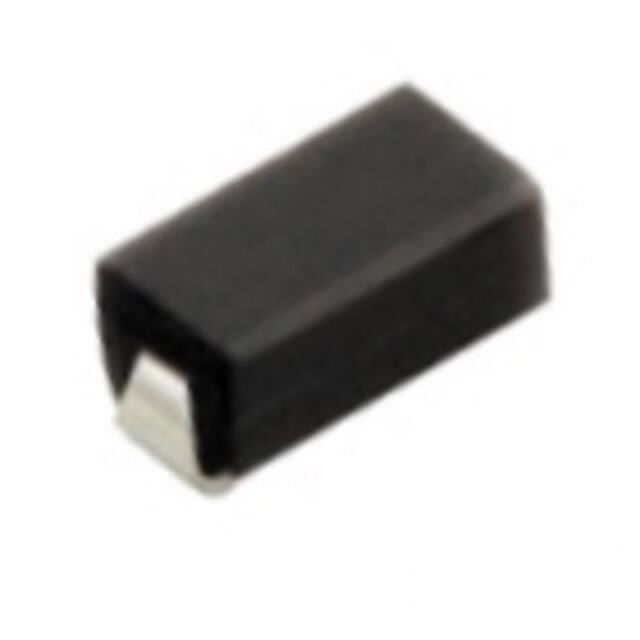
SURFACE MOUNT SILICON RECTIFIER
VOLTAGE RANGE 50 to 1000 Volts CURRENT 1.0 Ampere
FEATURES
* Ideal for surface mounted applications
* Low leakage current
* Metallurgically bonded construction
* Mounting position: Any
* Weight: 0.078 gram
SMX
MECHANICAL DATA
* Epoxy : Device has UL flammability classification 94V-0
.209 (5.31)
.185 (4.70)
.110 (2.79)
.086 (2.18)
Pin 2
Pin 1
.011 (0.28)
.180 (4.57)
.071 (1.80)
.160 (4.06)
.091 (2.31)
MAXIMUM RATINGS AND ELECTRICAL CHARACTERISTICS
.067 (1.70)
.059 (1.50)
Ratings at 25 OC ambient temperature unless otherwise specfied.
.035 (0.89)
( 0.13 )
( 0.05 )
.008 (0.20)
.051 (1.30)
.010 (0.25)
.007 (0.18)
Single phase, half wave, 60 Hz, resistive or inductive load.
For capacitive load, derate current by 20%.
Dimensions in inches and (millimeters)
MAXIMUM RATINGS (@ TA=25 OC unless otherwise noted)
SYMBOL
FM4001W
FM4002W
FM4003W
FM4004W
FM4005W
FM4006W
Maximum Recurrent Peak Reverse Voltage
VRRM
50
100
200
400
600
800
1000
Maximum RMS Voltage
VRMS
35
70
140
280
420
560
700
Vol ts
VDC
50
100
200
400
600
800
1000
Vol ts
RATINGS
Maximum DC Blocking Voltage
Maximum Average Forward Rectified Current
at Ambient Temperatu re
FM4007W UNITS
Vol ts
IO
1.0
Amps
I FSM
30
Amps
RθJA
RθJL
80
0
C/W
30
0
C/W
Typical Current Squared Time
I 2T
3.74
AS
Typical Junction Capacitance (Note 2)
CJ
15
pF
Peak Forward Surge Current 8.3 ms single half sine-wave
superimposed on rated load (JEDEC method)
Typical Thermal Resistance (Note 1)
Typical Thermal Resistance (Note 1)
Operating Temperature Range
Storage Temperature Range
2
TJ
-55 to + 150
0
C
T STG
-55 to + 150
0
C
ELECTRICAL CHARACTERISTICS (@TA=25 OC unless otherwise noted)
CHARACTERISTICS
SYMBOL
Maximum Instantaneous Forward Voltage at 1.0A DC
FM4001W
VF
Maximum Full Load Reverse Current,
Full cycle Average at T A=75 OC
o
Maximum Average Reverse Current
@T A = 25 C
at Rated DC Blocking Voltage
@T A = 150 o C
IR
NOTES : 1. Thermal Resistance :Mounted on PCB.
2. Measured at 1 MHz and applied reverse voltage of 4.0 volts.
3. "ROHS compliant".
FM4002W
FM4003W
FM4004W
FM4005W
FM4006W
FM4007W UNITS
1.1
Vol ts
30
uA
5.0
uA
2.0
mA
2020-03
REV: F
�INSTANTANEOUS FORWARD CURRENT, ( uA)
AVERAGE FORWARD CURRENT, (A)
RATING AND CHARACTERISTICS CURVES ( FM4001W THRU FM4007W )
2.0
1.5
1.0
Single Phase Half Wave 60Hz
Resistive or Inductive Load
0.375" (9.5mm) Lead Length
0.5
0
0
25
50
75
100
125
150
175
100000
10000 TA = 150 OC
1000
O
TA = 25 C
10
1.0
0.1
20
0
O
Lead Temperature ( C)
FIG.1 TYPICAL FORWARD CURRENT
DERATING CURVE
CJ, JUNCTION CAPACITANCE, (pF)
1.0
TJ = 25 OC
Pulse width=300 S
1% Duty Cycle
0.5
1.0
1.5
2.0
2.5
3.0
80
100
120
140
3.5
4.0
4.5
40
TJ = 25 OC
20
10
8
6
4
2
1
5.0
0.4
0.1
INSTANTANEOUS FORWARD VOLTAGE, (V)
1.0
4
40 80
FIG.4 TYPICAL JUNCTION CAPACITANCE
30
8.3mS Single Half Sine-Wave
JEDEC Method
25
20
15
10
0
1
10
REVERSE VOLTAGE, (V)
FIG.3 MAXIMUM INSTANTANEOUS FORWARD
CHARACTERISTICS
PEAK FORWARD SURGE CURRENT, (A)
INSTANTANEOUS REVERSE CURRENT, (A)
10
0
60
FIG.2 MAXIMUM REVERSE
CHARACTERISTICS
20
0.1
40
PERCENT OF RATED PEAK REVERSE VOLTAGE, (%)
2
4
6
8 10
20
40
80 100
NUMBER OF CYCLES AT 60Hz
FIG.5 MAXIMUM NON-REPETITIVE FORWARD
SURGE CURRENT
�Mounting Pad Layout
0.074 MAX.
(1.88 MAX.)
0.066MIN.
1.68 MIN.)
0.060 MIN.
(1.52 MIN.)
0.208
5.28) REF
Dimensions in inches and (millimeters)
�RECTRON
Attachment information about FM400XW
1. Internal Circuit
Anode
Cathode
2. Marking on the body
Part No.
Voltage-code
A X
V X
Cathode Band
Plant - code
Year – code
˄Y: Last digit of year &
A:2010,B:2011……)
X
X 1-------50V
2-------100V
3-------200V
4-------400V
5-------600V
6-------800V
7-------1000V
Week – code
(WW:01~52)
�REEL TAPING SPECIFICATIONS FOR
SURFACE MOUNT DEVICES-FLAT MELF
( SMA/SMB/SMC/SMX )
P0
P1
d
Pin 1
E
F
B
W
Pin 2
A
P
o
T
MAX. 3
A
D1
D2
o
MAX. 3
R
W1
D
C
Fig.: Configuration of FLAT MELF TAPING
(SMA/SMB/SMC/SMX)
ITEM
Carrier width
Carrier length
Carrier depth
Sprocket hole
SYMBOL
A
B
C
d
DO214AC (SMA) mm(inch)
2.6 0.15 (0.102 0.006)
5.15 0.15 (0.203 0.006)
2.3 0.15 (0.091 0.006)
1.5 0.1 (0.059 0.004)
DO214AA (SMB) mm(inch)
3.65 0.1 (0.144 0.004)
5.69 0.1 (0.224 0.004)
2.67 0.1 (0.105 0.004)
1.5 0.1 (0.059 0.004)
Reel outside diameter
Reel inner diameter
Feed hole diameter
Strocket hole position
Punch hole position
Punch hole pitch
D
D1
D2
E
F
P
178
2.0 (7.0 0.079)
50 Min.
13
13 0.5 (0.512 0.020)
1.75 0.1 (0.059 0.004) 1.75
5.65 0.05 (0.222 0.002) 5.65
4.0 0.1 (0.157 0.004)
8.0
Sprocket hole pitch
Embossment center
Totall tape thickness
Tape width
Reel width
P0
P1
T
W
W1
4.0 0.1 (0.157
2.0 0.1 (0.079
0.30 0.05 (0.012
12.0 0.2 (0.472
16.8 2.0 (0.661
178
0.004)
0.004)
0.002)
0.008)
0.079)
2.0 (7.0
0.079)
DO214AB (SMC) mm(inch)
6.0 0.1 (0.236 0.004)
8.30
0.1 (0.327
0.004)
2.5
0.1 (0.098
0.004)
1.5
0.1 (0.059
178
2.0 (7.0
0.004)
0.079)
50 Min.
50 Min.
13 0.5 (0.512 0.020)
0.5 (0.512 0.020)
0.1 (0.059 0.004) 1.75 0.1 (0.059 0.004)
0.05 (0.222 0.002) 7.5 0.05 (0.301 0.002)
8.0 0.1 (0.315 0.004)
0.1 (0.315 0.004)
4.0
2.0
0.1 (0.157 0.004)
0.1 (0.079 0.004)
0.6 Max.
12.0 0.2 (0.472 0.008)
16.8 2.0 (0.661 0.079)
4.0
2.0
0.1 (0.157 0.004)
0.1 (0.157 0.004)
0.6 Max.
16.0 0.2 (0.630 0.008)
24.0 2.0 (0.945 0.079)
Note: 1.Devices are packed in accordance with EIA standard RS-481-D and specification given above.
2.Available on 7 inch ( 1500 ct. ) or 13 inch ( 5000 ct. ) diameter reels.
Visit http:// www.rectron.com for complete datasheets
�PACKAGING OF DIODE AND BRIDGE RECTIFIERS
REEL PACK
PACKAGE
SMX
PACKAGE
SMX
PACKING EA PER EA PER COMPONENT TAPE SPACE REEL DIA CARTON SIZE EA PER
GROSS
SPACE
INNER
REEL
CARTON
WEIGHT(Kg)
CODE
(mm)
(mm)
(mm)
(mm)
BOX
-W
7,500
15,000
---
---
330
360*355*360
120,000
15.2
PACKING EA PER EA PER COMPONENT TAPE SPACE REEL DIA CARTON SIZE EA PER
GROSS
SPACE
INNER
REEL
CARTON WEIGHT(Kg)
CODE
(mm)
(mm)
(mm)
(mm)
BOX
-T
2,000
8,000
---
---
178
390*205*310
64,000
7.8
�DISCLAIMER NOTICE
Rectron Inc reserves the right to make changes without notice to any product
specification herein, to make corrections, modifications, enhancements or other
changes. Rectron Inc or anyone on its behalf assumes no responsibility or liability for any errors or inaccuracies. Data sheet specifications and its information
contained are intended to provide a product description only. "Typical" parameters which may be included on RECTRON data sheets and/ or specifications can and do vary in different applications and actual performance may vary over time. Rectron Inc does not assume any liability arising out of the application or
use of any product or circuit.
Rectron products are not designed, intended or authorized for use in medical,
life-saving implant or other applications intended for life-sustaining or other related applications where a failure or malfunction of component or circuitry may directly or indirectly cause injury or threaten a life without expressed written approval of Rectron Inc. Customers using or selling Rectron components for use in
such applications do so at their own risk and shall agree to fully indemnify Rectron Inc and its subsidiaries harmless against all claims, damages and expenditures.
�
很抱歉,暂时无法提供与“FM4004W-W”相匹配的价格&库存,您可以联系我们找货
免费人工找货