0
登录后你可以
  • 下载海量资料
  • 学习在线课程
  • 观看技术视频
  • 写文章/发帖/加入社区
会员中心
创作中心
发布
  • 发文章

  • 发资料

  • 发帖

  • 提问

  • 发视频

创作活动
RL205

RL205

  • 厂商:

    RECTRON

  • 封装:

    DO-204AC

  • 描述:

    DIODE GEN PURP 1000V 2A DO-15

  • 详情介绍
  • 数据手册
  • 价格&库存
RL205 数据手册
RL201 THRU RL207 SILICON RECTIFIER VOLTAGE RANGE 1000 Volts CURRENT 2.0 Amperes FEATURES * * * * Low cost Low leakage Low forward voltage drop High current capability MECHANICAL DATA * * * * * Case: Molded plastic Epoxy: Device has UL flammability classification 94V-O Lead: MIL-STD-202E method 208C guaranteed Mounting position: Any Weight: 0.40 gram .035 (0.88) 1.0 (25.4) .027 (0.68) DIA. MIN. .300 (7.6) .230 (5.8) .140 (3.6) .104 (2.6) DIA. 1.0 (25.4) MAXIMUM RATINGS AND ELECTRICAL CHARACTERISTICS MIN. o Ratings at 25 C ambient temperature unless otherwise specified. Single phase, half wave, 60 Hz, resistive or inductive load. For capacitive load, derate current by 20%. Dimensions in inches and (millimeters) MAXIMUM RATINGS (At T A = 25 C unless otherwise noted) o SYMBOL RATINGS RL201 RL202 RL203 RL204 RL205 RL206 RL207 UNITS Maximum Recurrent Peak Reverse Voltage VRRM 1000 Volts Maximum RMS Voltage VRMS 700 Volts VDC 1000 Volts IO 2.0 Amps I FSM 70 Amps 2 I t 20.33 A2/Sec CJ 20 RQJA T J , T STG 40 -55 to + 150 Maximum DC Blocking Voltage Maximum Average Forward Rectified Current o at T A = 75 C Peak Forward Surge Current, 8.3 ms single half sine-wave superimposed on rated load (JEDEC method) Typical Current Squarad Time Typical Junction Capacitance (Note) Typical Thermal Resistance Operating and Storage Temperature Range pF 0 C/ W 0 C ELECTRICAL CHARACTERISTICS (At TA = 25 C unless otherwise noted) o CHARACTERISTICS Maximum Instantaneous Forward Voltage at 2.0A DC Maximum DC Reverse Current @T A = 25 oC o at Rated DC Blocking Voltage @T A = 150 C Maximum Full Load Reverse Current Average, Full Cycle .375” (9.5mm) lead length at TL = 75oC NOTES : 1. Measured at 1 MHZ and applied reverse voltage of 4.0 volts SYMBOL VF IR RL201 RL202 RL203 RL204 1.0 1.0 2.0 30 RL205 RL206 RL207 UNITS Volts uAmps mAmps uAmps 2021-06 REV:F RATING AND CHARACTERISTIC CURVES ( RL201 THRU RL207 ) FIG. 2 - TYPICAL INSTANTANEOUS FORWARD CHARACTERISTICS 2.5 INSTANTANEOUS FORWARD CURRENT, (A) AVERAGE FORWARD CURRENT, (A) FIG. 1 - TYPICAL FORWARD CURRENT DERATING CURVE 2.0 1.5 1.0 Single Phase Half Wave 60Hz Inductive or Resistive Load .5 25 50 75 100 125 150 175 AMBIENT TEMPERATURE, ( ) INSTANTANEOUS REVERSE CURRENT, (uA) FIG. 3 - MAXIMUM NON-REPETITIVE FORWARD SURGE CURRENT 8.3ms Single Half Sine-Wave (JEDED Method) 60 40 20 5 1 2 4 6 8 10 20 40 60 80100 NUMBER OF CYCLES AT 60Hz .4 .2 .1 TJ = 25 Pulse Width=300uS 1% Duty Cycle .04 .8 1.0 1.2 1.4 1.5 INSTANTANEOUS FORWARD VOLTAGE, (V) FIG. 4 - MAXIMUM REVERSE CHARACTERISTICS 10000 TA = 150 1000 1.0 TA = 25 .1 0 20 40 60 80 100 120 140 PERCENT OF RATED PEAK REVERSE VOLTAGE, (%) FIG. 5 - TYPICAL JUNCTION CAPACITANCE JUNCTION CAPACITANCE, (pF) PEAK FORWARD SURGE CURRENT, (A) 100 80 4 2 1.0 .02 .01 .6 0 0 20 10 200 100 60 40 20 10 TJ = 25 6 4 2 1 .1 .2 .4 1.0 2 4 10 20 40 100 REVERSE VOLTAGE, ( V ) AXIAL LEAD TAPING SPECIFICATIONS FOR RECTIFIERS Axial lead devices are packed in accordance with EIA standard RS-296-D and specifications given below. COMPNENT OUTLINE COMPONENT PITCH A 0.5mm (.020") T-1 R-1 A-405 A-405 DO-41 DO-41 DO-15 R-3 DO-201AD R-6 INNER TAPE PITCH B 0.5mm (.020") 1.5mm (.059") 5.0mm 5.0mm 5.0mm 5.0mm 5.0mm 5.0mm 5.0mm 5.0mm 10.0mm 10.0mm 26.0mm 26.0mm 26.0mm 52.4mm 26.0mm 52.4mm 52.4mm 52.4mm 52.4mm 52.4mm O Z 90 5 CUMULATIVE PITCH TOLERANCE 2.0mm/20pitch 2.0mm/20pitch 2.0mm/20pitch 2.0mm/20pitch 2.0mm/20pitch 2.0mm/10pitch 2.0mm/10pitch 2.0mm/10pitch 2.0mm/10pitch 2.0mm/10pitch O DO A E W L1 D1 B L2 D T E Fig.: Configuration of AXIAL LEAD TAPING ITEM Component alignment Tape width Exposed adhesive Body eccentricity Reel outside diameter Reel inner diameter Feed hole diameter Reel width Notes : SYMBOL Z T E IL1-L2I D D1 DO W SPECIFICATIONS (mm) 1.2 Max. 6.0 0.4 0.8 Max. 1.0 Max. 330.0 85.7 0.3 30.5 0.4 79.0 1.0 1.Each component lead shall be sandwiched between tapes for a minimum of 3.2mm (0.126"). 2.The reel width "W" for 26mm taping is 50.0 1.0mm (1.97" 0.040"). SPECIFICATIONS (inch) 0.047 Max. 0.236 0.016 0.032 Max. 0.039 Max. 13.0 3.374 0.012 1.201 0.016 3.110 0.039 PACKAGING OF DIODE AND BRIDGE RECTIFIERS BULK PACK PACKAGE PACKING CODE DO-15 -B EA PER BOX INNER BOX SIZE (mm) 500 194*84*21 CARTON SIZE EA PER CARTON (mm) 415*220*255 25,000 GROSS WEIGHT(Kg) 12.74 REEL PACK PACKAGE DO-15 PACKING EA PER EA PER COMPONENT TAPE SPACE REEL DIA CARTON SIZE EA PER GROSS SPACE INNER REEL CARTON WEIGHT(Kg) CODE (mm) (mm) (mm) (mm) BOX -T 4,000 4,000 5.0 52 330 355*350*335 16,000 10.05 AMMO PACK PACKAGE PACKING CODE REEL ( EA ) DO-15 -F 1,500 COMPONENT TAPE SPACE SPACE(mm) (mm) 5.0 52 BOX SIZE (mm) CARTON SIZE(mm) 255*73*100 400*268*225 CARTON ( EA ) 15,000 GROSS WEIGHT (Kg) 8.8 RECTRON Attachment information about RL20X 1. Internal Circuit Anode Cathode 2. Marking on the body Cathode Band Plant - code Rectron Logo Part No. V X R L 2 X 0 H Year – code (Y: Last digit of year & A:2010,B:2011......) Month – code (M:0~9,O,N,D) H---for all Voltage rang DISCLAIMER NOTICE Rectron Inc reserves the right to make changes without notice to any product specification herein, to make corrections, modifications, enhancements or other changes. Rectron Inc or anyone on its behalf assumes no responsibility or liability for any errors or inaccuracies. Data sheet specifications and its information contained are intended to provide a product description only. "Typical" parameters which may be included on RECTRON data sheets and/ or specifications can and do vary in different applications and actual performance may vary over time. Rectron Inc does not assume any liability arising out of the application or use of any product or circuit. Rectron products are not designed, intended or authorized for use in medical, life-saving implant or other applications intended for life-sustaining or other related applications where a failure or malfunction of component or circuitry may directly or indirectly cause injury or threaten a life without expressed written approval of Rectron Inc. Customers using or selling Rectron components for use in such applications do so at their own risk and shall agree to fully indemnify Rectron Inc and its subsidiaries harmless against all claims, damages and expenditures.
RL205
物料型号: - RL201至RL207,这些是硅整流器的型号,电压范围为1000伏特,电流为2.0安培。

器件简介: - 这些整流器具有低成本、低漏电流、低正向电压降和高电流承载能力的特点。

引脚分配: - 文档中没有明确指出引脚分配,但通常整流器会有阳极(Anode)和阴极(Cathode)两个引脚。

参数特性: - 最大重复峰值反向电压(VRRM):RL204至RL207为1000伏特。 - 最大有效值电压(VRMS):RL204为700伏特。 - 最大直流阻断电压(VDC):RL204至RL207为1000伏特。 - 最大平均正向整流电流在75°C时(Io):RL204为2.0安培。 - 峰值正向浪涌电流(IFSM):RL202为70安培。 - 典型电流上升时间(序):RL201为20.33安培^2/秒。 - 典型结电容(CJ):RL202为20皮法拉德。 - 典型热阻(ROJA):RL202为40摄氏度/瓦特。 - 工作和存储温度范围(TJ.TSTG):RL202为-55至+150摄氏度。

功能详解: - 文档提供了正向电流、正向瞬时特性、反向浪涌电流、最大非重复正向浪涌电流和最大反向特性的图表。

应用信息: - 这些整流器适用于单相、半波、60赫兹、电阻性或电感性负载。对于电容器负载,需要将电流降低20%。
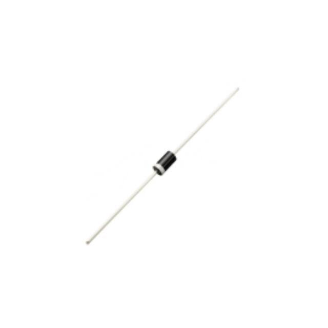
封装信息: - 封装类型为DO-15,采用模塑塑料封装,环氧树脂具有UL可燃性分类94V-0,引脚符合MIL-STD-202E方法208C保证。

包装信息: - 整流器的包装信息包括散装、卷装和弹药包装,每种包装方式都有相应的包装代码、每盒/卷的数量、内盒尺寸、纸箱尺寸、每箱的数量和毛重。
RL205 价格&库存

很抱歉,暂时无法提供与“RL205”相匹配的价格&库存,您可以联系我们找货

免费人工找货