709169/59L
HIGH-SPEED 16/8K x 9
SYNCHRONOUS PIPELINED
DUAL-PORT STATIC RAM
LEAD FINISH (SnPb) ARE IN EOL PROCESS - LAST TIME BUY EXPIRES JUNE 15, 2018
Features
◆
◆
◆
◆
◆
◆
True Dual-Ported memory cells which allow simultaneous
access of the same memory location
High-speed clock to data access
– Commercial: 6.5/7.5/9ns (max.)
Industrial: 7.5ns (max.)
Low-power operation
– IDT709169/59L
Active: 925mW (typ.)
Standby: 2.5mW (typ.)
Flow-Through or Pipelined output mode on either Port via
the FT/PIPE pins
Counter enable and reset features
Dual chip enables allow for depth expansion without
additional logic
◆
Full synchronous operation on both ports
– 3.5ns setup to clock and 0ns hold on all control, data, and
address inputs
– Data input, address, and control registers
– Fast 6.5ns clock to data out in the Pipelined output mode
– Self-timed write allows fast cycle time
– 10ns cycle time,100MHz operation in Pipelined output mode
TTL- compatible, single 5V (±10%) power supply
Industrial temperature range (–40°C to +85°C) is
available for 83MHz
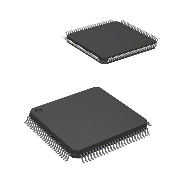
Available in a 100-pin Thin Quad Flatpack (TQFP) and 100pin fine pitch Ball Grid Array (fpBGA) packages.
S
R
T
O
R
F
A
P
D
E DE
T
E EN
S
L
N
O
M
G
S
I
M
B
S
O
E
O EC
D
R
W
E
T
N
O
N
◆
◆
◆
Functional Block Diagram
R/WR
OER
R/WL
OEL
CE0L
CE1L
FT/PIPEL
0/1
1
0
0
1
0/1
FT/PIPER
I/O0R - I/O8R
I/O0L - I/O8L
I/O
Control
I/O
Control
A13L(1)
A0L
CLKL
ADSL
CNTENL
CNTRSTL
CE0R
CE1R
1
0
0/1
1
0
0/1
A13R(1)
Counter/
Address
Reg.
MEMORY
ARRAY
Counter/
Address
Reg.
A0R
CLKR
ADSR
CNTENR
CNTRSTR
5653 drw 01
NOTE:
1. A13 is a NC for IDT709159.
APRIL 2019
1
DSC-5653/4
�IDT709169/59L
High-Speed 16/8K x 9 Synchronous Pipelined Dual-Port Static RAM
Description
The IDT709169/59 is a high-speed 16/8K x 9 bit synchronous DualPort RAM. The memory array utilizes Dual-Port memory cells to allow
simultaneous access of any address from both ports. Registers on
control, data, and address inputs provide minimal setup and hold
times. The timing latitude provided by this approach allows systems
to be designed with very short cycle times.
Industrial and Commercial Temperature Ranges
With an input data register, the IDT709169/59 has been optimized for
applications having unidirectional or bidirectional data flow in bursts.
An automatic power down feature, controlled by CE0 and CE1, permits
the on-chip circuitry of each port to enter a very low standby power
mode. Fabricated using IDT’s CMOS high-performance technology,
these devices typically operate on only 925mW of power.
Pin Configurations(1,2,3,4)
NC
NC
A6L
A5L
A4L
A3L
A2L
A1L
A0L
CNTENL
CLKL
ADSL
GND
GND
ADSR
CLKR
CNTENR
A0R
A1R
A2R
A3R
A4R
A5R
A6R
NC
06/28/02
Index
100 99 98 97 96 95 94 93 92 91 90 89 88 87 86 85 84 83 82 81 80 79 78 77 76
75
2
74
3
73
NC
NC
A7L
A8L
A9L
A10L
A11L
A12L
1
A13L(1)
NC
NC
NC
VCC
NC
NC
NC
NC
CE0L
CE1L
CNTRSTL
R/WL
OEL
FT/PIPEL
NC
NC
9
4
72
5
71
6
70
7
69
8
68
10
709169/59PF
PN100-1(5)
11
12
13
67
66
65
100-Pin TQFP
Top View(6)
64
63
14
62
15
61
16
60
17
59
18
58
19
57
20
56
21
55
22
54
23
53
24
52
GND
I/O8L
I/O7L
I/O6L
I/O5L
I/O4L
I/O3L
I/O2L
GND
I/O1L
I/O0L
VCC
GND
I/O0R
I/O1R
I/O2R
VCC
I/O3R
I/O4R
I/O5R
I/O6R
I/O7R
I/O8R
NC
NC
51
25
26 27 28 29 30 31 32 33 34 35 36 37 38 39 40 41 42 43 44 45 46 47 48 49 50
NOTES:
1. A13 is a NC for IDT709159.
2. All VCC pins must be connected to power supply.
3. All GND pins must be connected to ground supply.
4. Package body is approximately 14mm x 14mm x 1.4mm.
5. This package code is used to reference the package diagram.
6. This text does not indicate orientation of the actual part-marking.
2
6.42
NC
NC
A7R
A8R
A9R
A10R
A11R
A12R
A13R(1)
NC
NC
NC
GND
NC
NC
NC
NC
CE0R
CE1R
CNTRSTR
R/WR
OER
FT/PIPER
GND
NC
.
5653 drw 02
�IDT709169/59L
High-Speed 16/8K x 9 Synchronous Pipelined Dual-Port Static RAM
Industrial and Commercial Temperature Ranges
Pin Configurations (con't.)(1,2,3,4)
709169/59BF
BF100(5)
100-Pin fpBGA
Top View(6)
06/28/02
A1
A6R
B1
A4R
C1
A3R
D1
A0R
E1
A2
A9R
B2
A5R
C2
NC
D2
CLKR
E2
GND ADSR
F1
F2
GND CLKL
G1
CNTENL
H1
A2L
J1
NC
K1
A6L
G2
NC
H2
A4L
J2
A7L
K2
A8L
A3
A4
A12R
B3
A8R
C3
NC
D3
A1R
E3
CNTENR
F3
A0L
G3
A5L
H3
A9L
J3
A10L
K3
A11L
NC
B4
A10R
C4
A7R
D4
A2R
E4
A1L
F4
A3L
G4
A5
B5
NC
C5
NC
K4
NC
B6
D5
NC
B7
NC
C6
NC
NC
C7
A8
A9
R/WR GND
B8
B9
OER
C8
NC
C9
A10
NC
B10
I/O6R
C10
CE0R CE1R PL/FTR I/O7R I/O3R
D6
D8
D7
D9
D10
A11R A13R(1) CNTRSTR I/O8R I/O5R I/O1R
E5
ADSL
F5
E6
G5
NC
H5
GND
G6
R/WL
H6
NC
J5
NC
K5
VCC
E7
E8
E9
GND I/O4R I/O2R I/O0R
F6
VCC
A13L(1)
J4
A7
GND GND
A12L
H4
A6
F7
VCC
G7
NC
H7
NC
CE1L
J6
NC
K6
VCC
J7
OEL
K7
CE0L
F8
I/O2L
G8
I/O4L
H8
I/O7L
J8
GND
F9
I/O1L
G9
E10
VCC
F10
I/O0L
G10
GND I/O3L
H9
I/O6L
J9
GND
H10
I/O5L
J10
I/O8L
K8
K9
CNTRST L
PL/FTL NC
K10
5653 drw 03
NOTES:
1. A13 is a NC for IDT709159.
2. All VCC pins must be connected to power supply.
3. All GND pins must be connected to ground supply.
4. Package body is approximately 10mm x 10mm x 1.4mm with 0.8mm ball pitch.
5. This package code is used to reference the package diagram.
6. This text does not indicate orientation of the actual part-marking.
3
6.42
,
�IDT709169/59L
High-Speed 16/8K x 9 Synchronous Pipelined Dual-Port Static RAM
Industrial and Commercial Temperature Ranges
Pin Names
Left Port
Right Port
Names
CE0L, CE1L
CE0R, CE1R
Chip Enables
R/WL
R/WR
Read/Write Enable
OEL
OER
Output Enable
A0L - A13L(1)
A0R - A13R(1)
Address
I/O0L - I/O8L
I/O0R - I/O8R
Data Input/Output
CLKL
CLKR
Clock
ADSL
ADSR
Address Strobe
CNTENL
CNTENR
Counter Enable
CNTRSTL
CNTRSTR
Counter Reset
FT/PIPE L
FT/PIPER
Flow-Through/Pipeline
VCC
Power (5V)
GND
Ground (0V)
5653 tbl 01
NOTE:
1. A13 is a NC for IDT709159.
Truth Table I—Read/Write and Enable Control(1,2,3)
OE
CLK
CE0
CE 1
R/W
I/O0-8
X
↑
H
X
X
High-Z
Deselected—Power Down
X
↑
X
L
X
High-Z
Deselected—Power Down
X
↑
L
H
L
DATAIN
Write
L
↑
L
H
H
DATAOUT
Read
H
X
L
H
X
High-Z
Mode
Outputs Disabled
5653 tbl 02
NOTES:
1. "H" = VIH, "L" = VIL, "X" = Don't Care.
2. ADS, CNTEN, CNTRST = X.
3. OE is an asynchronous input signal.
4
6.42
�IDT709169/59L
High-Speed 16/8K x 9 Synchronous Pipelined Dual-Port Static RAM
Industrial and Commercial Temperature Ranges
Truth Table II—Address Counter Control(1,2)
External
Address
Previous
Internal
Address
Internal
Address
Used
CLK
ADS
CNTEN
CNTRST
I/O(3)
An
X
An
↑
L(4)
X
H
DI/O (n)
X
An
An + 1
↑
H
L(5)
H
DI/O(n+1)
Counter Enabled—Internal Address generation
X
An + 1
An + 1
↑
H
H
H
DI/O(n+1)
External Addre ss Blocked—Counter disab led (An + 1 reused)
X
(4)
DI/O(0)
X
X
A0
↑
X
L
MODE
External Address Used
Counter Reset to Address 0
5653 tbl 03
NOTES:
1. "H" = VIH, "L" = VIL, "X" = Don't Care.
2. CE0 and OE = VIL; CE1 and R/W = VIH.
3. Outputs configured in Flow-Through Output mode: if outputs are in Pipelined mode the data out will be delayed by one cycle.
4. ADS and CNTRST are independent of all other signals including CE0 and CE1.
5. The address counter advances if CNTEN = VIL on the rising edge of CLK, regardless of all other signals including CE0 and CE1.
Recommended Operating
Temperature and Supply Voltage
Grade
Commercial
Industrial
Recommended DC Operating
Conditions
Symbol
Ambient
Temperature(1)
GND
Vcc
0OC to +70OC
0V
5.0V + 10%
-40OC to +85OC
0V
5.0V + 10%
NOTES:
1. This is the parameter TA. This is the "instant on" case temperature.
5653 tbl 04
Parameter
Min.
Typ.
Max.
Unit
4.5
5.0
5.5
V
0
0
0
V
VCC
Supply Voltage
GND
Ground
VIH
Input High Voltage
2.2
____
6.0(1)
V
VIL
Input Low Voltage
-0.5(2)
____
0.8
V
5653 tbl 05
NOTES:
1. VTERM must not exceed Vcc + 10%.
2. VIL > -1.5V for pulse width less than 10ns.
Capacitance(1)
Absolute Maximum Ratings(1)
Symbol
Commercial
& Industrial
Unit
Terminal Voltage
with Respect
to GND
-0.5 to +7.0
V
TBIAS
Temperature
Under Bias
-55 to +125
o
TSTG
Storage
Temperature
-65 to +150
o
IOUT
DC Output
Current
(2)
VTERM
Rating
(TA = +25°C, f = 1.0MHz)
Symbol
Input Capacitance
CIN
(3)
COUT
50
C
C
mA
Parameter
Output Capacitance
Conditions(2)
Max.
Unit
VIN = 3dV
9
pF
VOUT = 3dV
10
pF
5653 tbl 07
NOTES:
1. These parameters are determined by device characterization, but are not
production tested.
2. 3dV references the interpolated capacitance when the input and output switch from
0V to 3V or from 3V to 0V.
3. COUT also references CI/O.
5653 tbl 06
NOTES:
1. Stresses greater than those listed under ABSOLUTE MAXIMUM RATINGS may
cause permanent damage to the device. This is a stress rating only and functional
operation of the device at these or any other conditions above those indicated in the
operational sections of this specification is not implied. Exposure to absolute
maximum rating conditions for extended periods may affect reliability.
2. VTERM must not exceed Vcc + 10% for more than 25% of the cycle time or 10ns
maximum, and is limited to < 20mA for the period of VTERM > Vcc + 10%.
5
6.42
�IDT709169/59L
High-Speed 16/8K x 9 Synchronous Pipelined Dual-Port Static RAM
Industrial and Commercial Temperature Ranges
DC Electrical Characteristics Over the Operating
Temperature Supply Voltage Range (VCC = 5.0V ± 10%)
709169/59L
Symbol
Parameter
Test Conditions
Min.
Max.
Unit
|ILI|
Input Leakage Current(1)
VCC = 5.5V, VIN = 0V to V CC
___
5
µA
|ILO|
Output Leakage Current
CE0 = VIH or CE1 = VIL, VOUT = 0V to V CC
___
5
µA
VOL
Output Low Voltage
IOL = +4mA
___
0.4
V
VOH
Output High Voltage
IOH = -4mA
2.4
___
V
5653 tbl 08
NOTE:
1. At Vcc < 2.0V input leakages are undefined.
DC Electrical Characteristics Over the Operating
Temperature and Supply Voltage Range(3) (VCC = 5V ± 10%)
709169/59L6
Com'l Only
Symbol
ICC
ISB1
ISB2
ISB3
ISB4
Parameter
Test Condition
Version
709169/59L7
Com'l & Ind
709169/59L9
Com'l Only
Typ.(4)
Max.
Typ.(4)
Max.
Typ.(4)
Max.
Unit
mA
Dynamic Operating
Current
(Both Ports Active)
CEL and CER= VIL
Outputs Disabled
f = fMAX(1)
COM'L
L
230
430
210
400
185
360
IND
L
____
____
210
440
____
____
Standby Current
(Both Ports - TTL
Level Inputs)
CEL = CER = VIH
f = fMAX(1)
COM'L
L
45
115
40
105
35
95
IND
L
____
____
40
120
____
____
Standby Current
(One Port - TTL
Level Inputs)
CE"A" = VIL and
CE"B" = VIH(3)
Active Port Outputs
Disabled, f=fMAX(1)
COM'L
L
150
235
135
220
120
205
IND
L
____
_____
135
235
____
____
Full Standby Current
(Both Ports CMOS Level Inputs)
Both Ports CER and
CEL > VCC - 0.2V
VIN > VCC - 0.2V or
VIN < 0.2V, f = 0(2)
COM'L
L
0.5
3.0
0.5
3.0
0.5
3.0
IND
L
____
_____
0.5
3.0
____
____
Full Standby Current
(One Port CMOS Level Inputs)
CE"A" < 0.2V and
CE"B" > VCC - 0.2V(5)
VIN > VCC - 0.2V or
VIN < 0.2V, Active Port
Outputs Disabled, f = fMAX(1)
COM'L
L
160
210
130
190
110
170
IND
L
____
_____
130
205
____
____
mA
mA
mA
mA
5653 tbl 09
NOTES:
1. At f = fMAX, address and control lines (except Output Enable) are cycling at the maximum frequency clock cycle of 1/tCYC, using "AC TEST CONDITIONS" at input levels of
GND to 3V.
2. f = 0 means no address, clock, or control lines change. Applies only to input at CMOS level standby.
3. Port "A" may be either left or right port. Port "B" is the opposite from port "A".
4. Vcc = 5V, TA = 25°C for Typ, and are not production tested. ICC DC(f=0) = 150mA (Typ).
5. CEX = VIL means CE0X = VIL and CE1X = VIH
CEX = VIH means CE0X = VIH or CE1X = VIL
CEX < 0.2V means CE0X < 0.2V and CE1X > VCC - 0.2V
CEX > VCC - 0.2V means CE0X > VCC - 0.2V or CE1X < 0.2V
"X" represents "L" for left port or "R" for right port.
6
6.42
�IDT709169/59L
High-Speed 16/8K x 9 Synchronous Pipelined Dual-Port Static RAM
Industrial and Commercial Temperature Ranges
AC Test Conditions
Input Pulse Levels
GND to 3.0V
Input Rise/Fall Times
2ns Max.
Input Timing Reference Levels
1.5V
Output Reference Levels
1.5V
Output Load
Figures 1, 2 and 3
5653 tbl 10
5V
5V
893Ω
DATAOUT
893Ω
DATAOUT
30pF
347Ω
347Ω
5653 drw 04
5653 drw 05
Figure 2. Output Test Load
(For tCKLZ, tCKHZ, tOLZ, and tOHZ).
*Including scope and jig.
Figure 1. AC Output Test load.
8
7
- 10pF is the I/O capacitance
of this device, and 30pF is the
AC Test Load Capacitance
6
tCD1,
tCD2
(Typical, ns)
5
4
3
2
1
0
-1
5pF*
20 40 60 80 100 120 140 160 180 200
Capacitance (pF)
5653 drw 06
Figure 3. Typical Output Derating (Lumped Capacitive Load).
7
6.42
�IDT709169/59L
High-Speed 16/8K x 9 Synchronous Pipelined Dual-Port Static RAM
Industrial and Commercial Temperature Ranges
AC Electrical Characteristics Over the Operating Temperature Range
(Read and Write Cycle Timing)(3) (VCC = 5V ± 10%, TA = 0°C to +70°C)
709169/59L6
Com'l Only
Symbol
tCYC1
tCYC2
Parameter
Clock Cycle Time (Flow-Through)(2)
(2)
709169/59L9
Com'l Only
Min.
Max.
Min.
Max.
Min.
Max.
Unit
19
____
22
____
25
____
ns
10
____
12
____
15
____
ns
tCH1
(2)
Clock High Time (Flow-Through)
6.5
____
7.5
____
12
____
ns
tCL1
Clock Low Time (Flow-Through)(2)
6.5
____
7.5
____
12
____
ns
(2)
4
____
5
____
6
____
ns
(2)
4
____
5
____
6
____
ns
tCH2
Clock Cycle Time (Pipelined)
709169/59L7
Com'l & Ind
Clock High Time (Pipelined)
tCL2
Clock Low Time (Pipelined)
tR
Clock Rise Time
____
3
____
3
____
3
ns
tF
Clock Fall Time
____
3
____
3
____
3
ns
tSA
Address Setup Time
3.5
____
4
____
4
____
ns
tHA
Address Hold Time
0
____
0
____
1
____
ns
tSC
Chip Enable Setup Time
3.5
____
4
____
4
____
ns
tHC
Chip Enable Hold Time
0
____
0
____
1
____
ns
tSB
Byte Enable Setup Time
3.5
____
4
____
4
____
ns
tHB
Byte Enable Hold Time
0
____
0
____
1
____
ns
tSW
R/W Setup Time
3.5
____
4
____
4
____
ns
tHW
R/W Hold Time
0
____
0
____
1
____
ns
tSD
Input Data Setup Time
3.5
____
4
____
4
____
ns
tHD
Input Data Hold Time
0
____
0
____
1
____
ns
ADS Setup Time
3.5
____
4
____
4
____
ns
tHAD
ADS Hold Time
0
____
0
____
1
____
ns
tSCN
CNTEN Setup Time
3.5
____
4
____
4
____
ns
tHCN
CNTEN Hold Time
0
____
0
____
1
____
ns
CNTRST Setup Time
3.5
____
4
____
4
____
ns
tHRST
CNTRST Hold Time
0
____
0
____
1
____
ns
tOE
Output Enable to Data Valid
____
6.5
____
7.5
____
9
ns
tOLZ
Output Enable to Output Low-Z(1)
2
____
2
____
2
____
ns
tOHZ
(1)
Output Enable to Output High-Z
tCD1
Clock to Data Valid (Flow-Through)(2)
tSAD
tSRST
(2)
tCD2
Clock to Data Valid (Pipelined)
tDC
Data Output Hold After Clock High
1
7
1
7
1
7
ns
____
15
____
18
____
20
ns
____
6.5
____
7.5
____
9
ns
2
____
2
____
2
____
ns
tCKHZ
(1)
Clock High to Output High-Z
2
9
2
9
2
9
ns
tCKLZ
Clock High to Output Low-Z(1)
2
____
2
____
2
____
ns
Port-to-Port Delay
tCWDD
Write Port Clock High to Read Data Delay
____
24
____
28
____
35
ns
tCCS
Clock-to-Clock Setup Time
____
9
____
10
____
15
ns
5653 tbl 11
NOTES:
1. Transition is measured 0mV from Low or High-impedance voltage with the Output Test Load (Figure 2). This parameter is guaranteed by device characterization, but is not production tested.
2. The Pipelined output parameters (tCYC2, tCD2) to either the Left or Right ports when FT/PIPE = VIH. Flow-Through parameters (tCYC1, tCD1) apply when FT/PIPE = VIL for
that port.
3. All input signals are synchronous with respect to the clock except for the asynchronous Output Enable (OE), FT/PIPER and FT/PIPEL.
8
6.42
�IDT709169/59L
High-Speed 16/8K x 9 Synchronous Pipelined Dual-Port Static RAM
Industrial and Commercial Temperature Ranges
Timing Waveform of Read Cycle for Flow-Through Output
(FT/PIPE"X" = VIL)(3,6)
tCYC1
tCH1
tCL1
CLK
CE0
tSC
tHC
tSW
tHW
tSA
tHA
tSC
tHC
CE1
R/W
(5)
ADDRESS
An
An + 1
tCD1
tCKLZ
An + 3
tCKHZ (1)
Qn
DATAOUT
OE
An + 2
tDC
Qn + 1
(1)
tOHZ
Qn + 2
(1)
tOLZ
tDC
(1)
(2)
tOE
5653 drw 07
Timing Waveform of Read Cycle for Pipelined Operation
(FT/PIPE"X" = VIH)(3,6)
tCYC2
tCH2
tCL2
CLK
CE0
tSC
tSC
tHC
tHC
(4)
CE1
R/W
(5)
ADDRESS
tSW
tHW
tSA
tHA
An
An + 1
(1 Latency)
An + 2
tDC
tCD2
DATAOUT
Qn
tCKLZ
An + 3
Qn + 1
(1)
tOHZ
Qn + 2
(1)
tOLZ
(6)
(1)
(2)
OE
tOE
5653 drw 08
NOTES:
1. Transition is measured 0mV from Low or High-impedance voltage with the Output Test Load (Figure 2).
2. OE is asynchronously controlled; all other inputs are synchronous to the rising clock edge.
3. ADS = VIL, CNTEN and CNTRST = VIH.
4. The output is disabled (High-Impedance state) by CE0 = VIH or CE1 = VIL following the next rising edge of the clock. Refer to Truth Table 1.
5. Addresses do not have to be accessed sequentially since ADS = VIL constantly loads the address on the rising edge of the CLK; numbers
are for reference use only.
6. "X" here denotes Left or Right port. The diagram is with respect to that port.
9
6.42
�IDT709169/59L
High-Speed 16/8K x 9 Synchronous Pipelined Dual-Port Static RAM
Industrial and Commercial Temperature Ranges
Timing Waveform of a Bank Select Pipelined Read(1,2)
tCH2
tCYC2
tCL2
CLK
tSA
A0
ADDRESS(B1)
CE0(B1)
tHA
tSC
A6
A5
A4
A3
A2
A1
tHC
tSC tHC
tCD2
Q0
DATAOUT(B1)
tCD2
Q3
tCKLZ
(3)
tCKHZ (3)
tHA
A0
ADDRESS(B2)
tCKHZ
Q1
tDC
tDC
tSA
(3)
tCD2
A6
A5
A4
A3
A2
A1
tSC tHC
CE0(B2)
tSC
tHC
tCKHZ (3)
tCD2
DATAOUT(B2)
tCKLZ
(3)
Q2
tCD2
Q4
tCKLZ (3)
5653 drw 09
Timing Waveform of Write with Port-to-Port Flow-Through Read(4,5,7)
CLK "A"
tSW tHW
R/W "A"
tSA
ADDRESS "A"
NO
MATCH
MATCH
tSD
DATAIN "A"
tHA
tHD
VALID
tCCS
(6)
CLK "B"
tCD1
R/W "B"
ADDRESS "B"
tSW
tHW
tSA
tHA
NO
MATCH
MATCH
tCWDD
(6)
tCD1
DATAOUT "B"
VALID
VALID
tDC
tDC
5653 drw 10
NOTES:
1. B1 Represents Bank #1; B2 Represents Bank #2. Each Bank consists of one IDT709169/59 for this waveform, and are setup for depth expansion in this
example. ADDRESS(B1) = ADDRESS(B2) in this situation.
2. OE and ADS = VIL; CE1(B1), CE1(B2), R/W, CNTEN, and CNTRST = VIH.
3. Transition is measured 0mV from Low or High-impedance voltage with the Output Test Load (Figure 2).
4. CE0 and ADS = VIL; CE1, CNTEN, and CNTRST = VIH.
5. OE = VIL for the Right Port, which is being read from. OE = VIH for the Left Port, which is being written to.
6. If tCCS < maximum specified, then data from right port READ is not valid until the maximum specified for tCWDD.
If tCCS > maximum specified, then data from right port READ is not valid until tCCS + tCD1. tCWDD does not apply in this case.
7. All timing is the same for both Left and Right ports. Port "A" may be either Left or Right port. Port "B" is the opposite from Port "A".
10
6.42
�IDT709169/59L
High-Speed 16/8K x 9 Synchronous Pipelined Dual-Port Static RAM
Industrial and Commercial Temperature Ranges
Timing Waveform of Pipelined Read-to-Write-to-Read (OE = VIL)(3)
tCYC2
tCH2
tCL2
CLK
CE0
tSC tHC
CE1
tSW tHW
R/W
(4)
ADDRESS
tSW tHW
An
tSA tHA
An +1
An + 2
An + 3
An + 2
An + 4
tSD tHD
DATAIN
Dn + 2
tCD2
(2)
tCKHZ
(1)
(1)
tCKLZ
tCD2
Qn + 3
Qn
DATAOUT
NOP(5)
READ
WRITE
READ
5653 drw 11
Timing Waveform of Pipelined Read-to-Write-to-Read (OE Controlled)(3)
tCH2
tCYC2
tCL2
CLK
CE0
tSC tHC
CE1
tSW tHW
R/W
(4)
ADDRESS
tSW tHW
An
tSA tHA
An +1
An + 2
An + 3
An + 4
An + 5
tSD tHD
DATAIN
Dn + 2
tCD2
(2)
Dn + 3
tCKLZ(1)
tCD2
Qn
DATAOUT
Qn + 4
tOHZ(1)
OE
READ
WRITE
READ
5653 drw 12
NOTES:
1. Transition is measured 0mV from Low or High-impedance voltage with the Output Test Load (Figure 2).
2. Output state (High, Low, or High-impedance) is determined by the previous cycle control signals.
3. CE0 and ADS = VIL; CE1, CNTEN, and CNTRST = VIH. "NOP" is "No Operation".
4. Addresses do not have to be accessed sequentially since ADS = VIL constantly loads the address on the rising edge of the CLK; numbers are for reference use only.
5. "NOP" is "No Operation." Data in memory at the selected address may be corrupted and should be re-written to guarantee data integrity.
11
6.42
�IDT709169/59L
High-Speed 16/8K x 9 Synchronous Pipelined Dual-Port Static RAM
Industrial and Commercial Temperature Ranges
Timing Waveform of Flow-Through Read-to-Write-to-Read (OE = VIL)(3)
tCH1
tCYC1
tCL1
CLK
CE0
tSC
tHC
CE1
tSW tHW
R/W
tSW tHW
(4)
An
tSA tHA
ADDRESS
An +1
An + 2
An + 4
An + 3
An + 2
tSD tHD
DATAIN
Dn + 2
tCD1
(2)
tCD1
Qn
DATAOUT
tCD1
tCD1
Qn + 3
Qn + 1
tDC
tCKHZ
(5)
NOP
READ
(1)
tCKLZ
WRITE
(1)
tDC
READ
5653 drw 13
Timing Waveform of Flow-Through Read-to-Write-to-Read (OE Controlled)(3)
tCYC1
tCH1
tCL1
CLK
CE0
tSC tHC
CE1
tSW tHW
R/W
tSW tHW
(4)
ADDRESS
tSA
An
tHA
An + 2
An +1
An + 4
An + 5
tSD tHD
DATAIN
Dn + 2
(2)
An + 3
Dn + 3
tDC
tCD1
Qn
DATAOUT
tOE
tCD1
(1)
tOHZ
tCKLZ
(1)
tCD1
Qn + 4
tDC
OE
READ
WRITE
READ
5653 drw 14
NOTES:
1. Transition is measured 0mV from Low or High-impedance voltage with the Output Test Load (Figure 2).
2. Output state (High, Low, or High-impedance is determined by the previous cycle control signals.
3. CE0 and ADS = VIL; CE1, CNTEN, and CNTRST = VIH. "NOP" is "No Operation".
4. Addresses do not have to be accessed sequentially since ADS = VIL constantly loads the address on the rising edge of the CLK; numbers are for reference use only.
5. "NOP" is "No Operation." Data in memory at the selected address may be corrupted and should be re-written to guarantee data integrity.
12
6.42
�IDT709169/59L
High-Speed 16/8K x 9 Synchronous Pipelined Dual-Port Static RAM
Industrial and Commercial Temperature Ranges
Timing Waveform of Pipelined Read with Address Counter Advance(1)
tCH2
tCYC2
tCL2
CLK
tSA
ADDRESS
tHA
An
tSAD tHAD
ADS
tSAD tHAD
CNTEN
tSCN tHCN
tCD2
DATAOUT
Qx - 1(2)
Qn + 2(2)
Qn + 1
Qn
Qx
Qn + 3
tDC
READ
EXTERNAL
ADDRESS
READ
WITH
COUNTER
COUNTER
HOLD
READ WITH COUNTER
5653 drw 15
Timing Waveform of Flow-Through Read with Address Counter Advance(1)
tCH1
tCYC1
tCL1
CLK
tSA
ADDRESS
tHA
An
tSAD tHAD
ADS
tSAD tHAD
tSCN tHCN
CNTEN
tCD1
DATAOUT
Qx(2)
Qn
Qn + 1
Qn + 2
Qn + 3(2)
Qn + 4
tDC
READ
EXTERNAL
ADDRESS
READ WITH COUNTER
COUNTER
HOLD
READ
WITH
COUNTER
5653 drw 16
NOTES:
1. CE0 and OE = VIL, CE1, R/W, and CNTRST = VIH.
2. If there is no address change via ADS = VIL (loading a new address) or CNTEN = VIL (advancing the address), i.e. ADS = VIH and CNTEN = VIH, then the data output
remains constant for subsequent clocks.
13
6.42
�IDT709169/59L
High-Speed 16/8K x 9 Synchronous Pipelined Dual-Port Static RAM
Industrial and Commercial Temperature Ranges
Timing Waveform of Write with Address Counter Advance
(Flow-Through or Pipelined Outputs)(1)
tCH2
tCYC2
tCL2
CLK
tSA
tHA
An
ADDRESS
INTERNAL(3)
ADDRESS
An(7)
An + 2
An + 1
An + 4
An + 3
tSAD tHAD
ADS
CNTEN
tSD tHD
Dn + 1
Dn
DATAIN
WRITE
EXTERNAL
ADDRESS
Dn + 1
Dn + 4
Dn + 3
Dn + 2
WRITE
WRITE
WITH COUNTER COUNTER HOLD
WRITE WITH COUNTER
5653 drw 17
Timing Waveform of Counter Reset (Pipelined Outputs)(2)
tCH2
tCYC2
tCL2
CLK
tSA tHA
ADDRESS(4)
INTERNAL(3)
ADDRESS
An
Ax(6)
0
1
An + 2
An + 1
An + 1
An
tSW tHW
R/W
ADS
CNTEN
tSRST tHRST
CNTRST
tSD
tHD
D0
DATAIN
Qn
Q1
Q0
DATAOUT(5)
.
COUNTER(6)
RESET
WRITE
ADDRESS 0
READ
ADDRESS 0
READ
ADDRESS 1
READ
ADDRESS n
READ
ADDRESS n+1
5653 drw 18
NOTES:
1. CE0 and R/W = VIL; CE1 and CNTRST = VIH.
2. CE0 = VIL; CE1 = VIH.
3. The "Internal Address" is equal to the "External Address" when ADS = VIL and equals the counter output when ADS = VIH.
4. Addresses do not have to be accessed sequentially since ADS = VIL constantly loads the address on the rising edge of the CLK; numbers are for reference use only.
5. Output state (High, Low, or High-impedance) is determined by the previous cycle control signals.
6. No dead cycle exists during counter reset. A READ or WRITE cycle may be coincidental with the counter reset cycle.
7. CNTEN = VIL advances Internal Address from ‘An’ to ‘An +1’. The transition shown indicates the time required for the counter to advance. The ‘An +1’ Address is written
to during this cycle.
14
6.42
�IDT709169/59L
High-Speed 16/8K x 9 Synchronous Pipelined Dual-Port Static RAM
Industrial and Commercial Temperature Ranges
A Functional Description
Depth and Width Expansion
The IDT709169/59 provides a true synchronous Dual-Port Static
RAM interface. Registered inputs provide minimal set-up and hold
times on address, data, and all critical control inputs. All internal
registers are clocked on the rising edge of the clock signal, however,
the self-timed internal write pulse is independent of the LOW to HIGH
transition of the clock signal.
An asynchronous output enable is provided to ease asynchronous
bus interfacing. Counter enable inputs are also provided to stall the
operation of the address counters for fast interleaved memory applications.
CE0 = VIH or CE1 = VIL for one clock cycle will power down the
internal circuitry to reduce static power consumption. Multiple chip
enables allow easier banking of multiple IDT709169/59's for depth
expansion configurations. When the Pipelined output mode is enabled, two
cycles are required to get valid data on the outputs.
The IDT709169/59 features dual chip enables (refer to Truth Table
I) in order to facilitate rapid and simple depth expansion with no requirements for external logic. Figure 4 illustrates how to control the various chip
enables in order to expand two devices in depth.
The IDT709169/59 can also be used in applications requiring expanded width, as indicated in Figure 4. Since the banks are allocated at
the discretion of the user, the external controller can be set up to drive the
input signals for the various devices as required to allow for 18-bit
or wider applications.
A14/A13(1)
IDT709169/59
CE0
CE1
CE1
VCC
CE1
IDT709169/59
VCC
CE1
CE0
CE0
Control Inputs
CE0
Control Inputs
Control Inputs
IDT709169/59
IDT709169/59
Control Inputs
5653 drw 19
Figure 4. Depth and Width Expansion with IDT709169/59
NOTE:
1. A14 is for IDT709169, A13 is for IDT709159.
15
6.42
CNTRST
CLK
ADS
CNTEN
R/W
OE
�IDT709169/59L
High-Speed 16/8K x 9 Synchronous Pipelined Dual-Port Static RAM
Industrial and Commercial Temperature Ranges
Ordering Information
XXXXX
A
99
A
A
Device
Type
Power
Speed
Package
Process/
Temperature
Range
Blank
I(1)
Commercial (0°C to +70°C)
Industrial (-40°C to +85°C)
PF
BF
100-pin TQFP (PN100-1)
100-pin fpBGA (BF100)
6
7
9
Commercial Only
Commercial & Industrial
Commercial Only
L
Low Power
Speed in nanoseconds
..
709169 144K (16K x 9-Bit) Synchronous Dual-Port RAM
709159 72K (8K x 9- Bit) Synchronous Dual-Port RAM
5653 drw 20
NOTE:
1. Contact your local sales office for Industrial temp range for other speeds, packages and powers.
LEAD FINISH (SnPb) parts are in EOL process. Product Discontinuation Notice - PDN# SP-17-02
IDT Clock Solution for IDT709169/59 Dual-Port
Dual-Port I/O Specitications
Clock Specifications
IDT Dual-Port
Part Number
Voltage
I/O
Input
Capacitance
709169/59
5
TTL
9pF
Input Duty
Maximum
Jitter
Cycle
Frequency Tolerance
Requirement
40%
100
150ps
IDT
PLL
Clock Device
IDT
Non-PLL Clock
Device
FCT88915TT
49FCT805T
49FCT806T
74FCT807T
5653 tbl 12
Datasheet Document History
07/08/02:
08/18/03:
01/29/09:
02/05/14:
04/26/19:
Initial Public Release
Removed Preliminary status
Page 16 Added IDT Clock Solution Table
Page 16 Removed "IDT" from orderable part number
709169 Changed to Obsolete Status
Product Discontinuation Notice - PDN# F-09-01
Datasheet changed to Obsolete Status
Product Discontinuation Notice - PDN# SP-17-02
Last time buy expires June 15, 2018
CORPORATE HEADQUARTERS
6024 Silver Creek Valley Road
San Jose, CA 95138
for SALES:
800-345-7015 or 408-284-8200
fax: 408-284-2775
www.idt.com
The IDT logo is a registered trademark of Integrated Device Technology, Inc.
16
6.42
for Tech Support:
408-284-2794
DualPortHelp@idt.com
�IMPORTANT NOTICE AND DISCLAIMER
RENESAS ELECTRONICS CORPORATION AND ITS SUBSIDIARIES (“RENESAS”) PROVIDES TECHNICAL
SPECIFICATIONS AND RELIABILITY DATA (INCLUDING DATASHEETS), DESIGN RESOURCES (INCLUDING
REFERENCE DESIGNS), APPLICATION OR OTHER DESIGN ADVICE, WEB TOOLS, SAFETY INFORMATION, AND
OTHER RESOURCES “AS IS” AND WITH ALL FAULTS, AND DISCLAIMS ALL WARRANTIES, EXPRESS OR IMPLIED,
INCLUDING, WITHOUT LIMITATION, ANY IMPLIED WARRANTIES OF MERCHANTABILITY, FITNESS FOR A
PARTICULAR PURPOSE, OR NON-INFRINGEMENT OF THIRD PARTY INTELLECTUAL PROPERTY RIGHTS.
These resources are intended for developers skilled in the art designing with Renesas products. You are solely responsible
for (1) selecting the appropriate products for your application, (2) designing, validating, and testing your application, and (3)
ensuring your application meets applicable standards, and any other safety, security, or other requirements. These
resources are subject to change without notice. Renesas grants you permission to use these resources only for
development of an application that uses Renesas products. Other reproduction or use of these resources is strictly
prohibited. No license is granted to any other Renesas intellectual property or to any third party intellectual property.
Renesas disclaims responsibility for, and you will fully indemnify Renesas and its representatives against, any claims,
damages, costs, losses, or liabilities arising out of your use of these resources. Renesas' products are provided only subject
to Renesas' Terms and Conditions of Sale or other applicable terms agreed to in writing. No use of any Renesas resources
expands or otherwise alters any applicable warranties or warranty disclaimers for these products.
(Rev.1.0 Mar 2020)
Corporate Headquarters
Contact Information
TOYOSU FORESIA, 3-2-24 Toyosu,
Koto-ku, Tokyo 135-0061, Japan
www.renesas.com
For further information on a product, technology, the most
up-to-date version of a document, or your nearest sales
office, please visit:
www.renesas.com/contact/
Trademarks
Renesas and the Renesas logo are trademarks of Renesas
Electronics Corporation. All trademarks and registered
trademarks are the property of their respective owners.
© 2020 Renesas Electronics Corporation. All rights reserved.
�