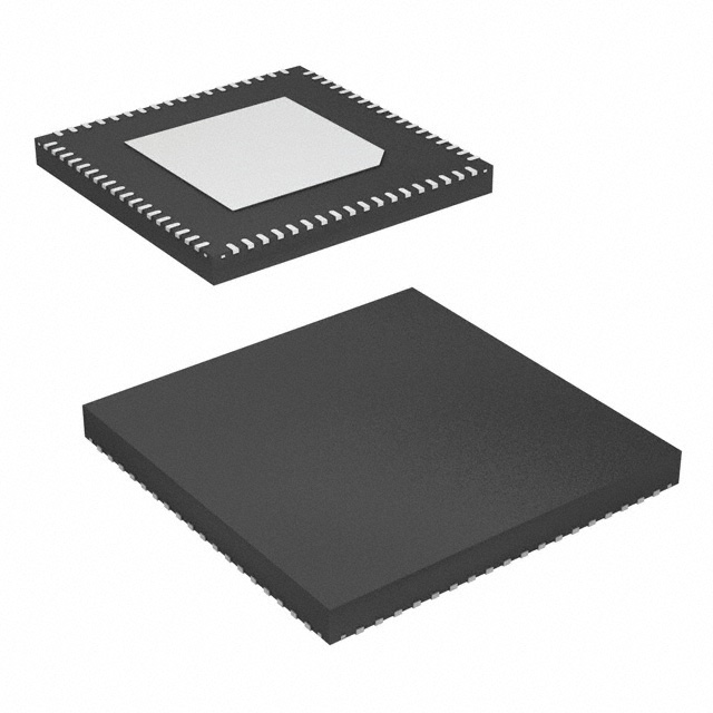
Synchronous Equipment Timing Source
for Synchronous Ethernet
Highlights
•
•
•
•
•
•
•
•
•
Synchronous Equipment Timing Source (SETS) for Synchronous
Ethernet (SyncE) per ITU-T G.8264
DPLL1 generates ITU-T G.8262 compliant SyncE clocks, Telcordia
GR-1244-CORE/GR-253-CORE, and ITU-T G.813 compliant SONET/
SDH clocks
DPLL2 performs rate conversions for synchronization interfaces or for
other general purpose timing applications
DPLL1 can be configured as a Digitally Controlled Oscillators (DCOs)
for PTP clock synthesis
DCO frequency resolution is [(77760 / 1638400) * 2^-48] or
~1.686305041e-10 ppm
APLL1 and APLL2 generate clocks with jitter < 1 ps RMS (12 kHz to
20 MHz) for: 1000BASE-T and 1000BASE-X
Fractional-N input dividers support a wide range of reference frequencies
Locks to 1 Pulse Per Second (PPS) references
DPLLs, APLL1 and APLL2 can be configured from an external
EEPROM after reset
•
•
•
•
•
•
•
•
•
Features
•
•
•
•
•
•
•
•
•
•
•
•
•
Differential reference inputs (IN1 to IN4) accept clock frequencies
between 1 PPS and 650 MHz
Single ended inputs (IN5 to IN6) accept reference clock frequencies
between 1 PPS and 162.5 MHz
Loss of Signal (LOS) pins (LOS0 to LOS3) can be assigned to any
clock reference input
Reference monitors qualify/disqualify references depending on activity, frequency and LOS pins
Automatic reference selection state machines select the active reference for each DPLL based on the reference monitors, priority tables,
revertive and non-revertive settings and other programmable settings
Fractional-N input dividers enable the DPLLs to lock to a wide range
of reference clock frequencies including: 10/100/1000 Ethernet, 10G
Ethernet, OTN, SONET/SDH, PDH, TDM, GSM, CPRI, and GNSS frequencies
Any reference inputs (IN1 to IN6) can be designated as external sync
pulse inputs (1 PPS, 2 kHz, 4 kHz or 8 kHz) associated with a selectable reference clock input
FRSYNC_8K_1PPS and MFRSYNC_2K_1PPS output sync pulses
that are aligned with the selected external input sync pulse input and
frequency locked to the associated reference clock input
DPLL1 can be configured with bandwidths between 0.09 mHz and
567 Hz
DPLL1 locks to input references with frequencies between 1 PPS and
650 MHz
DPLL2 locks to input references with frequencies between 8 kHz and
650 MHz
DPLL1 complies with ITU-T G.8262 for Synchronous Ethernet Equipment Clock (EEC), and G.813 for Synchronous Equipment Clock
©2018 Integrated Device Technology, Inc.
•
•
•
•
•
82P33714
Datasheet
(SEC); and Telcordia GR-253-CORE/ GR-1244-CORE for Stratum 3
and SONET Minimum Clock (SMC)
DPLL1 generates clocks with PDH, TDM, GSM, CPRI/OBSAI, 10/100/
1000 Ethernet and GNSS frequencies; these clocks are directly available on OUT1 and OUT8
DPLL2 generates N x 8 kHz clocks up to 100 MHz that are output on
OUT9 and OUT10
APLL1 and APLL2 are connected to DPLL1
APLL1 and APLL2 generate 10/100/1000 Ethernet, 10G Ethernet, or
SONET/SDH frequencies
Any of eight common TCXO/OCXO frequencies can be used for the
System Clock: 10 MHz, 12.8 MHz, 13 MHz, 19.44 MHz, 20 MHz,
24.576 MHz, 25 MHz or 30.72 MHz
The I2C slave, SPI or the UART interface can be used by a host processor to access the control and status registers
The I2C master interface can automatically load a device configuration from an external EEPROM after reset
Differential outputs OUT3 to OUT6 output clocks with frequencies
between 1 PPS and 650 MHz
Single ended outputs OUT1, OUT2, OUT7 and OUT8 output clocks
with frequencies between 1 PPS and 125 MHz
Single ended outputs OUT9 and OUT10 output clocks N*8 kHz multiples up to 100 MHz
DPLL1 supports independent programmable delays for each of IN1 to
IN6; the delay for each input is programmable in steps of 0.61 ns with
a range of ~±78 ns
The input to output phase delay of DPLL1 is programmable in steps of
0.0745 ps with a total range of ±20 s
The clock phase of each of the output dividers for OUT1 (from APLL1)
to OUT8 is individually programmable in steps of ~200 ps with a total
range of +/-180°
1149.1 JTAG Boundary Scan
72-QFN green package
Applications
•
•
•
•
•
•
•
•
•
1
Access routers, edge routers, core routers
Carrier Ethernet switches
Multi-service access platforms
PON OLT
LTE eNodeB
ITU-T G.8264 Synchronous Equipment Timing Source (SETS)
ITU-T G.8262 Synchronous Ethernet Equipment Clock (EEC)
ITU-T G.813 Synchronous Equipment Clock (SEC)
Telcordia GR-253-CORE/GR1244-CORE Stratum 3 Clock (S3) and
SONET Minimum Clock (SMC)
August 21, 2018
�82P33714 Datasheet
Description
The 82P33714 Synchronous Equipment Timing Source (SETS) for Synchronous Ethernet (SyncE) provides tools to manage timing references,
clock generation and timing paths for SyncE based clocks, per ITU-T G.8264 and ITU-T G.8262. 82P33714 meets the requirements of ITU-T G.8262
for synchronous Ethernet Equipment Clocks (EECs) and ITU-T G.813 for Synchronous Equipment Clocks (SEC). The device outputs low-jitter clocks
that can directly synchronize Ethernet interfaces; as well as SONET/SDH and PDH interfaces.
The 82P33714 accepts four differential reference inputs and two single ended reference inputs that can operate at common GNSS, Ethernet,
SONET/SDH and PDH frequencies that range from 1 Pulse Per Second (PPS) to 650 MHz. The references are continually monitored for loss of signal and for frequency offset per user programmed thresholds. All of the references are available to both Digital PLLs (DPLLs). The active reference for
each DPLL is determined by forced selection or by automatic selection based on user programmed priorities and locking allowances and based on
the reference monitors and LOS inputs.
The 82P33714 can accept a clock reference and an associated phase locked sync signal as a pair. DPLL1 can lock to the clock reference and
align the frame sync and multi-frame sync outputs with the paired sync input. The device allows any of the differential or single ended reference inputs
to be configured as sync inputs that can be associated with any of the other differential or single ended reference inputs. The input sync signals can
have a frequency of 1 PPS, 2 kHz, 4 kHz or 8 kHz. This feature enables DPLL1 to phase align its frame sync and multi-frame sync outputs with a sync
input without the need use a low bandwidth setting to lock directly to the sync input.
The DPLLs support three primary operating modes: Free-Run, Locked and Holdover. In Free-Run mode the DPLLs synthesize clocks based on
the system clock alone. In Locked mode the DPLLs filter reference clock jitter with the selected bandwidth. In Locked mode, the long-term output frequency accuracy is the same as the long term frequency accuracy of the selected input reference. In Holdover mode, the DPLL uses frequency data
acquired while in Locked mode to generate accurate frequencies when input references are not available.
DPLL1 also supports DCO mode. In DCO mode the DPLL control loop is opened and the DCO can be controlled by an IEEE 1588 clock recovery
servo running on an external processor to synthesize IEEE 1588 clocks.
The 82P33714 requires a system clock for its reference monitors and other digital circuitry. The frequency accuracy of the system clock determines the frequency accuracy of the DPLLs in Free-Run mode. The frequency stability of the system clock determines the frequency stability of the
DPLLs in Free-Run mode and in Holdover mode; and it affects the wander generation of the DPLLs in Locked mode.
When used with a suitable system clock, DPLL1 meets the frequency accuracy, pull-in, hold-in, pullout, noise generation, noise tolerance, transient response, and holdover performance requirements of the following applications: ITU-T G.8262/G.813 EEC/SEC options 1 and 2, Telcordia GR1244 Stratum 3 (S3), Telcordia GR-253-CORE S3 and SONET Minimum Clock (SMC).
DPLL1 can be configured with a range of selectable filtering bandwidths from 0.09 MHz to 567 Hz. The 17 MHz bandwidth can be used to lock the
DPLL directly to a 1 PPS reference. The 92 MHz bandwidth can be used for G.8262/G.813 Option 2, or Telcordia GR-253-CORE S3, or SMC applications. The bandwidths in the range 1.1 Hz to 8.9 Hz can be used for G.8262/G.813 Option 1 applications. The bandwidth of 1.1 Hz or 2.2 Hz can be
used for Telcordia GR-1244-CORE S3 applications. Bandwidths above 10 Hz can be used in jitter attenuation and rate conversion applications.
DPLL2 is a wideband (BW > 25Hz) frequency translator that can be used, for example, to convert a recovered line clock to a 1.544 MHz or 2.048
MHz synchronization interface clock.
For SETS applications per ITU-T G.8264, DPLL1 is configured as an EEC/SEC to output clocks for the T0 reference point and DPLL2 is used to
output clocks for the T4 reference point.
Clocks generated by DPLL1 can be passed through APLL1 or APLL2 which are LC based jitter attenuating Analog PLLs (APLLs). The output
clocks generated by APLL1 and APLL2 are suitable for serial GbE and lower rate interfaces.
All 82P33714 control and status registers are accessed through an I2C slave, SPI or UART interface. For configuring the DPLLs, APLL1 and
APLL2, the I2C master interface can automatically load a configuration from an external EEPROM after reset.
©2018 Integrated Device Technology, Inc.
2
August 21, 2018
�82P33714 Datasheet
Block Diagram
System Clock
LOS0 / XO_FREQ0
LOS1 / XO_FREQ1
LOS2 / XO_FREQ2
SYS PLL
LOS3
APLL1
IN1(P/N)
IN2(P/N)
IN3(P/N)
IN4(P/N)
IN5
IN6
DPLL1
(T0)
Reference
monitors
APLL2
Reference
selection
Frac-N input
dividers
DPLL2
(T4)
ex_sync module
I2C Master
I2C Slave,
SPI, UART
Control and
Status
Registers
OutDiv
OUT1
OutDiv
OUT2
OutDiv
OUT3 (P/N)
OutDiv
OUT4 (P/N)
OutDiv
OUT5 (P/N)
OutDiv
OUT6 (P/N)
OutDiv
OUT7
OutDiv
OUT8
OutDiv
OUT9
OutDiv
OUT10
FRSYNC_8K_1PPS
MFRSYNC_2K_1PPS
JTAG
Figure 1. Functional Block Diagram
©2018 Integrated Device Technology, Inc.
3
August 21, 2018
�82P33714 Datasheet
Contents
Highlights . . . . . . . . . . . . . . . . . . . . . . . . . . . . . . . . . . . . . . . . . . . . . . . . . . . . . . . . . . . . . . . . . . . . . . . . . . . . . . . . . . . . . . . . . . . . . . . . .
Features . . . . . . . . . . . . . . . . . . . . . . . . . . . . . . . . . . . . . . . . . . . . . . . . . . . . . . . . . . . . . . . . . . . . . . . . . . . . . . . . . . . . . . . . . . . . . . . . . .
Applications . . . . . . . . . . . . . . . . . . . . . . . . . . . . . . . . . . . . . . . . . . . . . . . . . . . . . . . . . . . . . . . . . . . . . . . . . . . . . . . . . . . . . . . . . . . . . . .
Description . . . . . . . . . . . . . . . . . . . . . . . . . . . . . . . . . . . . . . . . . . . . . . . . . . . . . . . . . . . . . . . . . . . . . . . . . . . . . . . . . . . . . . . . . . . . . . . .
Block Diagram . . . . . . . . . . . . . . . . . . . . . . . . . . . . . . . . . . . . . . . . . . . . . . . . . . . . . . . . . . . . . . . . . . . . . . . . . . . . . . . . . . . . . . . . . . . . .
Pin Assignment. . . . . . . . . . . . . . . . . . . . . . . . . . . . . . . . . . . . . . . . . . . . . . . . . . . . . . . . . . . . . . . . . . . . . . . . . . . . . . . . . . . . . . . . . . . . .
Pin Description . . . . . . . . . . . . . . . . . . . . . . . . . . . . . . . . . . . . . . . . . . . . . . . . . . . . . . . . . . . . . . . . . . . . . . . . . . . . . . . . . . . . . . . . . . . . .
Recommendations for Unused Input and Output Pins . . . . . . . . . . . . . . . . . . . . . . . . . . . . . . . . . . . . . . . . . . . . . . . . . . . . . . . . .
Inputs . . . . . . . . . . . . . . . . . . . . . . . . . . . . . . . . . . . . . . . . . . . . . . . . . . . . . . . . . . . . . . . . . . . . . . . . . . . . . . . . . . . . . . . .
Outputs . . . . . . . . . . . . . . . . . . . . . . . . . . . . . . . . . . . . . . . . . . . . . . . . . . . . . . . . . . . . . . . . . . . . . . . . . . . . . . . . . . . . . . .
RESET OPERATION . . . . . . . . . . . . . . . . . . . . . . . . . . . . . . . . . . . . . . . . . . . . . . . . . . . . . . . . . . . . . . . . . . . . . . . . . . . . . . . . . .
MS/SL PIN USAGE . . . . . . . . . . . . . . . . . . . . . . . . . . . . . . . . . . . . . . . . . . . . . . . . . . . . . . . . . . . . . . . . . . . . . . . . . . . . . . . . . . .
Functional Description . . . . . . . . . . . . . . . . . . . . . . . . . . . . . . . . . . . . . . . . . . . . . . . . . . . . . . . . . . . . . . . . . . . . . . . . . . . . . . . . . . . . . . .
Synchronous Ethernet, sonet, and sdh Architecture . . . . . . . . . . . . . . . . . . . . . . . . . . . . . . . . . . . . . . . . . . . . . . . . . . . . . . . . . .
Hardware functional description . . . . . . . . . . . . . . . . . . . . . . . . . . . . . . . . . . . . . . . . . . . . . . . . . . . . . . . . . . . . . . . . . . . . . . . . . .
System clock. . . . . . . . . . . . . . . . . . . . . . . . . . . . . . . . . . . . . . . . . . . . . . . . . . . . . . . . . . . . . . . . . . . . . . . . . . . . . . . . . . .
Modes of operation . . . . . . . . . . . . . . . . . . . . . . . . . . . . . . . . . . . . . . . . . . . . . . . . . . . . . . . . . . . . . . . . . . . . . . . . . . . . . .
Input Clocks and frame sync. . . . . . . . . . . . . . . . . . . . . . . . . . . . . . . . . . . . . . . . . . . . . . . . . . . . . . . . . . . . . . . . . . . . . . .
DPLL Locking Process . . . . . . . . . . . . . . . . . . . . . . . . . . . . . . . . . . . . . . . . . . . . . . . . . . . . . . . . . . . . . . . . . . . . . . . . . . .
APLL1 and APLL2 . . . . . . . . . . . . . . . . . . . . . . . . . . . . . . . . . . . . . . . . . . . . . . . . . . . . . . . . . . . . . . . . . . . . . . . . . . . . . .
Output Clocks & Frame Sync Signals. . . . . . . . . . . . . . . . . . . . . . . . . . . . . . . . . . . . . . . . . . . . . . . . . . . . . . . . . . . . . . . .
Input and output Phase control. . . . . . . . . . . . . . . . . . . . . . . . . . . . . . . . . . . . . . . . . . . . . . . . . . . . . . . . . . . . . . . . . . . . .
Power Supply Filtering Techniques . . . . . . . . . . . . . . . . . . . . . . . . . . . . . . . . . . . . . . . . . . . . . . . . . . . . . . . . . . . . . . . . . . . . . . . . . . . . .
Microprocessor Interface . . . . . . . . . . . . . . . . . . . . . . . . . . . . . . . . . . . . . . . . . . . . . . . . . . . . . . . . . . . . . . . . . . . . . . . . . . . . . . . . . . . . .
I2C Slave Mode . . . . . . . . . . . . . . . . . . . . . . . . . . . . . . . . . . . . . . . . . . . . . . . . . . . . . . . . . . . . . . . . . . . . . . . . . . . . . . . . . . . . . .
I2C Device Address . . . . . . . . . . . . . . . . . . . . . . . . . . . . . . . . . . . . . . . . . . . . . . . . . . . . . . . . . . . . . . . . . . . . . . . . . . . . .
I2C Bus Timing . . . . . . . . . . . . . . . . . . . . . . . . . . . . . . . . . . . . . . . . . . . . . . . . . . . . . . . . . . . . . . . . . . . . . . . . . . . . . . . . .
Supported Transactions . . . . . . . . . . . . . . . . . . . . . . . . . . . . . . . . . . . . . . . . . . . . . . . . . . . . . . . . . . . . . . . . . . . . . . . . . .
I2C Master Mode . . . . . . . . . . . . . . . . . . . . . . . . . . . . . . . . . . . . . . . . . . . . . . . . . . . . . . . . . . . . . . . . . . . . . . . . . . . . . . . . . . . . .
I2C Boot-up Initialization Mode. . . . . . . . . . . . . . . . . . . . . . . . . . . . . . . . . . . . . . . . . . . . . . . . . . . . . . . . . . . . . . . . . . . . .
EEPROM memory map notes. . . . . . . . . . . . . . . . . . . . . . . . . . . . . . . . . . . . . . . . . . . . . . . . . . . . . . . . . . . . . . . . . . . . . .
Serial Mode. . . . . . . . . . . . . . . . . . . . . . . . . . . . . . . . . . . . . . . . . . . . . . . . . . . . . . . . . . . . . . . . . . . . . . . . . . . . . . . . . . . . . . . . . .
UART Mode . . . . . . . . . . . . . . . . . . . . . . . . . . . . . . . . . . . . . . . . . . . . . . . . . . . . . . . . . . . . . . . . . . . . . . . . . . . . . . . . . . . . . . . . .
Protocol. . . . . . . . . . . . . . . . . . . . . . . . . . . . . . . . . . . . . . . . . . . . . . . . . . . . . . . . . . . . . . . . . . . . . . . . . . . . . . . . . . . . . . .
JTAG. . . . . . . . . . . . . . . . . . . . . . . . . . . . . . . . . . . . . . . . . . . . . . . . . . . . . . . . . . . . . . . . . . . . . . . . . . . . . . . . . . . . . . . . . . . . . . . . . . . . .
Thermal Management. . . . . . . . . . . . . . . . . . . . . . . . . . . . . . . . . . . . . . . . . . . . . . . . . . . . . . . . . . . . . . . . . . . . . . . . . . . . . . . . . . . . . . . .
Junction temperature . . . . . . . . . . . . . . . . . . . . . . . . . . . . . . . . . . . . . . . . . . . . . . . . . . . . . . . . . . . . . . . . . . . . . . . . . . . . . . . . . .
Thermal Release Path . . . . . . . . . . . . . . . . . . . . . . . . . . . . . . . . . . . . . . . . . . . . . . . . . . . . . . . . . . . . . . . . . . . . . . . . . . . . . . . . .
Electrical Specifications . . . . . . . . . . . . . . . . . . . . . . . . . . . . . . . . . . . . . . . . . . . . . . . . . . . . . . . . . . . . . . . . . . . . . . . . . . . . . . . . . . . . . .
Absolute Maximum Rating . . . . . . . . . . . . . . . . . . . . . . . . . . . . . . . . . . . . . . . . . . . . . . . . . . . . . . . . . . . . . . . . . . . . . . . . . . . . . .
Recommended Operation Conditions. . . . . . . . . . . . . . . . . . . . . . . . . . . . . . . . . . . . . . . . . . . . . . . . . . . . . . . . . . . . . . . . . . . . . .
I/O Specifications . . . . . . . . . . . . . . . . . . . . . . . . . . . . . . . . . . . . . . . . . . . . . . . . . . . . . . . . . . . . . . . . . . . . . . . . . . . . . . . . . . . . .
CMOS Input / Output Port. . . . . . . . . . . . . . . . . . . . . . . . . . . . . . . . . . . . . . . . . . . . . . . . . . . . . . . . . . . . . . . . . . . . . . . . .
LVPECL / LVDS Input / Output Port . . . . . . . . . . . . . . . . . . . . . . . . . . . . . . . . . . . . . . . . . . . . . . . . . . . . . . . . . . . . . . . . .
LVDS Input / Output Port . . . . . . . . . . . . . . . . . . . . . . . . . . . . . . . . . . . . . . . . . . . . . . . . . . . . . . . . . . . . . . . . . . . . . . . . .
Output Clock Duty Cycle. . . . . . . . . . . . . . . . . . . . . . . . . . . . . . . . . . . . . . . . . . . . . . . . . . . . . . . . . . . . . . . . . . . . . . . . . .
Jitter Performance . . . . . . . . . . . . . . . . . . . . . . . . . . . . . . . . . . . . . . . . . . . . . . . . . . . . . . . . . . . . . . . . . . . . . . . . . . . . . . . . . . . .
Input / Output Clock Timing . . . . . . . . . . . . . . . . . . . . . . . . . . . . . . . . . . . . . . . . . . . . . . . . . . . . . . . . . . . . . . . . . . . . . . . . . . . . .
©2018 Integrated Device Technology, Inc.
4
1
1
1
2
3
6
7
10
10
10
10
11
12
12
14
14
14
21
26
27
28
30
32
34
34
34
34
36
36
37
37
38
40
40
41
42
42
42
43
43
43
44
44
45
48
50
51
58
August 21, 2018
�82P33714 Datasheet
Output / output CLOCK TIMING . . . . . . . . . . . . . . . . . . . . . . . . . . . . . . . . . . . . . . . . . . . . . . . . . . . . . . . . . . . . . . . . . . . . . . . . . .
Package Outline Drawings . . . . . . . . . . . . . . . . . . . . . . . . . . . . . . . . . . . . . . . . . . . . . . . . . . . . . . . . . . . . . . . . . . . . . . . . . . . . . . . . . . . .
Ordering Information. . . . . . . . . . . . . . . . . . . . . . . . . . . . . . . . . . . . . . . . . . . . . . . . . . . . . . . . . . . . . . . . . . . . . . . . . . . . . . . . . . . . . . . . .
Revision History . . . . . . . . . . . . . . . . . . . . . . . . . . . . . . . . . . . . . . . . . . . . . . . . . . . . . . . . . . . . . . . . . . . . . . . . . . . . . . . . . . . . . . . . . . . .
©2018 Integrated Device Technology, Inc.
5
58
59
59
60
August 21, 2018
�82P33714 Datasheet
INT_REQ
IC
DPLL1_LOCK
56
55
OUT9
61
57
VDDD
62
MS/SL
OUT8
63
58
VDDDO
64
OUT10
OUT7
65
SONET/SDH/LOS3
VDDDO
66
59
OUT6_NEG
67
60
VDDAO
OUT6_POS
OUT5_NEG
70
68
OUT5_POS
71
69
VDDAO
72
PIN ASSIGNMENT
VC2
1
54
DPLL2_LOCK
VDDA
2
53
VDDD_1_8
VDDA
3
52
RSTB
VDDA
4
51
SDO/I2C_SDA/UART_TX
VDDA
5
50
SCLK/I2C_SCL
OSCi
6
49
CS/I2C_AD0
XO_FREQ0/LOS0
7
48
CLKE/I2C_AD1
XO_FREQ1/LOS1
8
47
SDI/I2C_AD2/UART_RX
XO_FREQ2/LOS2
9
46
MPU_MODE1/I2CM_SCL
45
MPU_MODE0/I2CM_SDA
8XXXXXX
82P33714
36
IN2_NEG
IN3_POS
34
IN2_POS
IN3_NEG
33
IN1_NEG
35
32
IN5
31
37
IN1_POS
18
30
TDO
OUT1
IN4_POS
VDDDO
38
29
17
28
IN4_NEG
TDI
OUT2
TCK
27
VDDD
39
VDDDO
40
16
26
15
25
TRSTB
OUT3_POS
IN6
OUT3_NEG
41
24
VDDD_1_8
14
VDDAO
VC1
TMS
23
FRSYNC_8K_1PPS
42
22
43
13
VSSAO
12
OUT4_NEG
VDDA
21
MFRSYNC_2K_1PPS
OUT4_POS
44
20
11
VDDAO
VDDA
19
VDDA
10
VSSAO
1
Figure 1. Pin Assignment (Top View)
©2018 Integrated Device Technology, Inc.
6
August 21, 2018
�82P33714 Datasheet
2
PIN DESCRIPTION
Table 1: Pin Description
Pin No.
Name
I/O
Type
Description
Global Control Signal
6
58
OSCI
MS/SL
I
I
pull-up
CMOS
CMOS
OSCI: Crystal Oscillator System Clock
A clock provided by a crystal oscillator is input on this pin. It is the system clock for the
device. The oscillator frequency is selected via pins XO_FREQ0 ~ XO_FREQ2
MS/SL: Master / Slave Selection
This pin, together with the MS_SL_CTRL bit, controls whether the device is configured as the
Master or as the Slave. The signal level on this pin is reflected by the MASTER_SLAVE bit.
MS_SL = 0: Slave
MS_SL = 1: Master (default with internal pull-up)
59
SONET/SDH/
LOS3
I
pull-down
CMOS
SONET/SDH: SONET / SDH Frequency Selection
During reset, this pin determines the default value of the IN_SONET_SDH bit:
High: The default value of the IN_SONET_SDH bit is ‘1’ (SONET);
Low: The default value of the IN_SONET_SDH bit is ‘0’ (SDH).
After reset, the value on this pin takes no effect.
LOS3- This pin is used to disqualify input clocks. See input clocks section for more details.
52
RSTB
I
pull-up
CMOS
RSTB: Reset
Refer to section 2.2 reset operation for details.
7
8
9
XO_FREQ0/
LOS0
XO_FREQ1/
LOS1
XO_FREQ2/
LOS2
31
32
IN1_POS
IN1_NEG
33
34
IN2_POS
IN2_NEG
35
36
IN3_POS
IN3_NEG
38
39
IN4_POS
IN4_NEG
37
IN5
41
IN6
XO_FREQ0 ~ XO_FREQ2: These pins set the oscillator frequency.
XO_FREQ[2:0] Oscillator Frequency (MHz)
000
10.000
001
12.800
010
13.000
I
011
19.440
CMOS
pull-down
100
20.000
101
24.576
110
25.000
111
30.720
LOS0 ~ LOS2 - These pins are used to disqualify input clocks. See input clocks section for
more details. After reset, this pin takes on the operation of LOS0-LOS2
Input Clock and Frame Synchronization Input Signal
IN1_POS / IN1_NEG: Positive / Negative Input Clock 1
I
PECL/LVDS A reference clock is input on this pin. This pin can also be used as a sync input, and in this
case a 2 kHz, 4 kHz, 8 kHz, or 1PPS signal can be input on this pin.
IN2_POS / IN2_NEG: Positive / Negative Input Clock 1
I
PECL/LVDS A reference clock is input on this pin. This pin can also be used as a sync input, and in this
case a 2 kHz, 4 kHz, 8 kHz, or 1PPS signal can be input on this pin.
IN3_POS / IN3_NEG: Positive / Negative Input Clock 3
I
PECL/LVDS A reference clock is input on this pin. This pin can also be used as a sync input, and in this
case a 2 kHz, 4 kHz, 8 kHz, or 1PPS signal can be input on this pin.
IN4_POS / IN4_NEG: Positive / Negative Input Clock 4
I
PECL/LVDS A reference clock is input on this pin. This pin can also be used as a sync input, and in this
case a 2 kHz, 4 kHz, 8 kHz, or 1PPS signal can be input on this pin.
IN5:
Input Clock 5
I
CMOS
A reference clock is input on this pin. This pin can also be used as a sync input, and in this
pull-down
case a 2 kHz, 4 kHz, 8 kHz, or 1PPS signal can be input on this pin.
IN6: Input Clock 6
I
CMOS
A reference clock is input on this pin. This pin can also be used as a sync input, and in this
pull-down
case a 2 kHz, 4 kHz, 8 kHz, or 1PPS signal can be input on this pin.
©2018 Integrated Device Technology, Inc.
7
August 21, 2018
�82P33714 Datasheet
Table 1: Pin Description (Continued)
Pin No.
Name
I/O
Type
Description
Output Frame Synchronization Signal
43
44
FRSYNC
_8K_1PPS
MFRSYNC
_2K_1PPS
O
CMOS
FRSYNC_8K_1PPS: 8 kHz Frame Sync Output
An 8 kHz signal or a 1PPS sync signal is output on this pin.
O
CMOS
MFRSYNC_2K_1PPS: 2 kHz Multiframe Sync Output
A 2 kHz signal or a 1PPS sync signal is output on this pin.
Output Clock
30
28
25
26
21
22
71
70
68
67
65
63
61
60
OUT1
OUT2
OUT3_POS
OUT3_NEG
OUT4_POS
OUT4_NEG
OUT5_POS
OUT5_NEG
OUT6_POS
OUT6_NEG
OUT7
OUT8
OUT9
OUT10
OUT1 ~ OUT2: Output Clock 1 ~ 2
O
CMOS
O
PECL/LVDS
OUT3_POS / OUT3_NEG: Positive / Negative Output Clock 3
This output is set to LVDS by default.
O
PECL/LVDS
OUT4_POS / OUT4_NEG: Positive / Negative Output Clock 4
This output is set to LVDS by default.
O
PECL/LVDS
OUT5_POS / OUT5_NEG: Positive / Negative Output Clock 5
This output is set to LVDS by default.
O
PECL/LVDS
OUT6_POS / OUT6_NEG: Positive / Negative Output Clock 6
This output is set to LVDS by default.
O
CMOS
O
CMOS
13
VC1
O
Analog
1
VC2
O
Analog
OUT7 ~ OUT8: Output Clock 7 ~ 8
OUT9 ~ OUT10: Output Clock 9 ~ 10
Miscellaneous
VC1: APLL1 VC Output
An external RC filter (a resistor in series with a capacitor to ground, and another capacitor in
parallel) should be connected to this pin.
VC2: APLL2 VC Output
An external RC filter (a resistor in series with a capacitor to ground, and another capacitor in
parallel) should be connected to this pin.
Lock Signal
54
DPLL2_LOCK
O
CMOS
55
DPLL1_LOCK
O
CMOS
DPLL2_LOCK
This pin goes high when DPLL2 is locked
DPLL1_LOCK
This pin goes high when DPLL1 is locked
Microprocessor Interface
57
46
45
INT_REQ
MPU_MODE1/
I2CM_SCL
MPU_MODE0/
I2CM_SDA
O
Tri-state
I/O
pull-up
©2018 Integrated Device Technology, Inc.
CMOS
INT_REQ: Interrupt Request
This pin is used as an interrupt request.
MPU_MODE[1:0]: Microprocessor Interface Mode Selection
During reset, these pins determine the default value of the MPU_SEL_CNFG[1:0] bits as follows:
00: I2C mode
01: SPI mode
CMOS/
10: UART mode
Open Drain
11: I2C master (EEPROM) mode
I2CM_SCL: Serial Clock Line
In I2C master mode, the serial clock is output on this pin.
I2CM_SDA: Serial Data Input for I2C Master Mode
In I2C master mode, this pin is used as the input for the serial data.
8
August 21, 2018
�82P33714 Datasheet
Table 1: Pin Description (Continued)
Pin No.
Name
I/O
Type
Description
SDI: Serial Data Input
In Serial mode, this pin is used as the serial data input. Address and data on this pin are serially clocked into the device on the rising edge of SCLK.
47
48
SDI/I2C_AD2/
UART_RX
CLKE/I2C_AD1
I
pull-down
I
pull-down
CMOS
CMOS
I2C_AD2: Device Address Bit 2
In I2C mode, I2C_AD[2:0] pins are the address bus of the microprocessor interface.
UART_RX
In UART mode, this pin is used as the receive data (UART Receive)
CLKE: SCLK Active Edge Selection
In Serial mode, this pin is an input, it selects the active edge of SCLK to update the SDO:
High - The falling edge;
Low - The rising edge.
I2C_AD1: Device Address Bit 1
In I2C mode, I2C_AD[2:0] pins are the address bus of the microprocessor interface.
49
50
51
CS/I2C_AD0
SCLK/I2C_SCL
SDO/I2C_SDA/
UART_TX
I
pull-up
I
pull-down
CMOS
CMOS
CS: Chip Selection
In Serial modes, this pin is an input. A transition from high to low must occur on this pin for
each read or write operation and this pin should remain low until the operation is over.
I2C_AD0: Device Address Bit 0
In I2C mode, I2C_AD[2:0] pins are the address bus of the microprocessor interface.
SCLK: Shift Clock
In Serial mode, a shift clock is input on this pin.
Data on SDI is sampled by the device on the rising edge of SCLK. Data on SDO is updated
on the active edge of SCLK. The active edge is determined by the CLKE.
I2C_SCL: Serial Clock Line
In I2C mode, the serial clock is input on this pin.
SDO: Serial Data Output
In Serial mode, this pin is used as the serial data output. Data on this pin is serially clocked
out of the device on the active edge of SCLK.
I/O
pull-up
I2C_SDA
CMOS/
I2C_SDA: Serial Data Input/Output
Open Drain
In I2C mode, this pin is used as the input/output for the serial data.
UART_TX:
In UART mode, this pin is used as the transmit data (UART Transmit)
JTAG (per IEEE 1149.1)
14
TMS
I
pull-up
CMOS
15
TRSTB
I
pull-up
CMOS
16
TCK
I
pull-down
CMOS
17
TDI
I
pull-up
CMOS
©2018 Integrated Device Technology, Inc.
TMS: JTAG Test Mode Select
The signal on this pin controls the JTAG test performance and is sampled on the rising edge
of TCK.
TRSTB: JTAG Test Reset (Active Low)
A low signal on this pin resets the JTAG test port.
This pin should be connected to ground when JTAG is not used.
TCK: JTAG Test Clock
The clock for the JTAG test is input on this pin. TDI and TMS are sampled on the rising edge
of TCK and TDO is updated on the falling edge of TCK.
If TCK is idle at a low level, all stored-state devices contained in the test logic will indefinitely
retain their state.
TDI: JTAG Test Data Input
The test data are input on this pin. They are clocked into the device on the rising edge of
TCK.
9
August 21, 2018
�82P33714 Datasheet
Table 1: Pin Description (Continued)
Pin No.
Name
18
TDO
I/O
O
tri-state
Type
Description
CMOS
TDO: JTAG Test Data Output
The test data are output on this pin. They are clocked out of the device on the falling edge of
TCK.
TDO pin outputs a high impedance signal except during the process of data scanning.
Power & Ground
2, 3, 4, 5, 10 11, 12
20, 24, 69, 72
27, 29, 64, 66
40, 62
42, 53
19,23
73 (e_PAD)
VDDA
VDDAO
VDDDO
VDDD
VDDD_1_8
VSSAO
VSS
Power
Power
Power
Power
Power
Ground
Ground
-
-
VDDA: Analog Core Power - +3.3V DC nominal
VDDAO: Analog Output Power - +3.3V DC nominal
VDDDO: Digital Output Power - +3.3V DC nominal
VDDD: Digital Core Power - +3.3V DC nominal
VDDD_1_8: Digital Core Power - +1.8V DC nominal
VSSAO: Ground
VSS: Ground
Other
56
2.1
2.1.1
IC
-
-
IC: Internal Connection
Internal Use. This pin must be left open for normal operation.
RECOMMENDATIONS FOR UNUSED INPUT
AND OUTPUT PINS
Differential Clock Outputs
All unused differential outputs can be left floating. We recommend
that there is no trace attached. Both sides of the differential output pair
should either be left floating or terminated.
INPUTS
Control Pins
2.2
All control pins have internal pull-ups or pull-downs; additional resistance is not required but can be added for additional protection. A 1kΩ
resistor can be used.
The device must be reset properly in order to ensure operations
conform with specification.
To properly reset the device, the RSTB pin must be held at a low
value for at least 50 usec. The device should be brought out of reset
only at the time when power supplies are stabilized and the system
clock is available on OSCi pin. The RSTB can be held low until this time,
or pulsed low for at least 50us after this time.
Single-Ended Clock Inputs
For protection, unused single-ended clock inputs should be tied to
ground.
Differential Clock Inputs
For applications not requiring the use of a differential input, both
*_POS and *_NEG can be left floating. Though not required, but for
additional protection, a 1kΩ resistor can be tied from _POS to ground.
2.1.2
The bootstrap pins (XO_FREQ[2:0], MPU_MODE[1:0], I2C_AD[2:0],
MS/SL, SONET/SDH) need to be held at desired states for at least 2ms
after de-assertion of RSTB pin to allow correct sampling. See Figure 3
for detail.
OUTPUTS
If loading from an EEPROM, the maximum time from RSTB deassert to have stable clocks is 100ms. Note that if there is a bad
EEPROM read sequence and the EEPROM loading is repeated once or
twice (three times halts the device), then this time can be 2 or 3 times
longer respectively. If not loading from EEPROM the maximum time
from RSTB de-assert to have stable clocks is 10ms.
Status Pins
For applications not requiring the use of a status pin, we recommend
bringing out to a test point for debugging purposes.
Single-Ended Clock Outputs
All unused single-ended clock outputs can be left floating, or can be
brought out to a test point for debugging purposes.
©2018 Integrated Device Technology, Inc.
RESET OPERATION
An on-board reset circuit or a commercially available voltage
supervisory can be used to generate the reset signal. It is also feasible
to use a standalone power-up RC reset circuit. When using a power-up
RC reset circuit, careful consideration must be taken into account to fine
tune the circuit properly based on each power supply's specification to
ensure the power supply rise time is fast enough with respect to the RC
time constant of the RC circuit.
10
August 21, 2018
�82P33714 Datasheet
VDDD
VDDA
OSCI
RSTB
Bootstrap
Pins*
50ȝs
2ms
* Bootstrap pins are: XO_FREQ[2:0], MPU_MODE[1:0], I2C_AD[2:0], MS/SL, SONET/SDH
Figure 2. Reset timing diagram
2.3
For more information, see AN-901, How to Implement Master/Slave
for SETS and SMU Devices on Timing Redundancy Designs.
MS/SL PIN USAGE
The MS/SL pin is used for timing card redundancy applications
where there is a primary and secondary timing card in the system. For
other applications, this pin should be left unconnected or connected to
an external pull-up.
©2018 Integrated Device Technology, Inc.
11
August 21, 2018
�82P33714 Datasheet
3
FUNCTIONAL DESCRIPTION
3.1
SYNCHRONOUS ETHERNET, SONET, AND
SDH ARCHITECTURE
Single
Blade
82P33714 integrates key features that allows the device to be used
in Synchronous Ethernet, SONET and SDH applications. There are several key synchronization standards that are important to meet for such a
system, they are:
•
ITU-T Recommendation G.8262, Timing characteristics of Synchronous Ethernet Equipment slave clock (EEC)
•
ITU-T Recommendation G.8264, Distribution of timing through
packet networks
•
ITU-T Recommendation G.812, Timing requirements of slave
clocks suitable for use as node clocks in synchronization networks.
•
ITU-T Recommendation G.813, Timing characteristics of SDH
equipment slave clocks (SEC).
•
GR-253-CORE - Telcordia Technologies Generic Requirements Issue 5, October 2009
•
GR-1244-CORE - Telcordia Technologies Generic Requirements Issue 4, October 2009
•
ATIS-0900101.2006 - T1.101 - Synchronization Interface Standard
BITS/SSU
SyncE (T0)
A
P
L
L
SyncE-TxCK
SyncE-RxCK
LOS
SyncE/
SONET
/SDH
PHY
Ethernet
CDR
T4
TCXO
Figure 3. SyncE/SONET/SDH single blade application
Figure 4 shows an active/redundant architecture, as described
before it is usually used in Telecom equipment that are designed to have
a redundant timing card in case of primary timing card failure. The
redundant timing card mimics the output of the active timing card, so in
case of failure the system will still provide proper synchronization.
Figure 3 shows a single blade architecture that it is usually used in
simple equipment.
©2018 Integrated Device Technology, Inc.
12
August 21, 2018
�82P33714 Datasheet
Timing Card
Line Card
SSU/BITS
SyncE (T0)
A
P
L
L
SyncE-TxCK
DPLL1
T4
A
P
L
L
SyncE-TxCK
SyncE-RxCK
LOS
SyncE/
SONET/
SDH
PHY
XO
Active/
redundant
connection
Line Card
DPLL1
LOS
Timing Card
SyncE (T0)
SyncE-TxCK
SyncE-RxCK
DPLL2
TCXO
SSU/BITS
A
P
L
L
DPLL2
A
P
L
L
SyncE/
SONET/
SDH
PHY
XO
SyncE-TxCK
Line Card
T4
TCXO
DPLL1
A
P
L
L
SyncE-TxCK
SyncE-RxCK
LOS
DPLL2
SyncE/
SONET/
SDH
PHY
XO
Figure 4. SyncE/SONET/SDH active/redundant application
©2018 Integrated Device Technology, Inc.
13
August 21, 2018
�82P33714 Datasheet
3.2
HARDWARE FUNCTIONAL DESCRIPTION
3.2.2
MODES OF OPERATION
3.2.1
SYSTEM CLOCK
3.2.2.1
DPLL1 Operating Mode
A crystal oscillator should be used as an input on the OSCI pin. This
clock is provided for the device as a system clock. The system clock is
used as a reference clock for all the internal circuits. The active edge of
the system clock can be selected by the OSC_EDGE bit in xo_freq_cnfg
register.
The DPLL1 can operate in several different modes as shown in
Table 3.
Eight common oscillator frequencies can be used for the stable System Clock. The oscillator frequency can be set by pins or by xo_freq_cnfg register as shown in Table 2.
Table 3: DPLL1 Operating Mode Control
The DPLL1 operating mode is controlled by the DPLL1_OPERATING_MODE[4:0] bits.
Table 2: Oscillator Frequencies
xo_freq[2:0] pins
xo_freq_cnfg[2:0] bits
Oscillator Frequency (MHz)
000
10.000
001
12.800
010
13.000
011
19.440
100
20.000
101
24.576
110
25.000
111
30.720
DPLL1 Operating Mode
00000
00001
00010
00011
00100
00101
00110
00111
01000-01001
Automatic
Forced - Free-Run
Forced - Holdover
Reserved
Forced - Locked
Forced - Pre-Locked2
Forced - Pre-Locked
Forced - Lost-Phase
Reserved
DCO write frequency
see Chapter 3.2.2.1.6
Reserved
Reserved
01010
10010 - 11111
10011-11111
When the operating mode is switched automatically, the operation of
the internal state machine is shown in Figure 5.
Whether the operating mode is under external control or is switched
automatically, the current operating mode is always indicated by the
DPLL1_OPERATING_STS[4:0] bits. When the operating mode
switches, the DPLL1_OPERATING_STS bit will be set. If the
DPLL1_OPERATING_STS bit is ‘1’, an interrupt will be generated if the
corresponding mask bit is set to “1”, the mask bit is set to “0” by default.
An offset from the nominal frequency may be compensated by setting the NOMINAL_FREQ_VALUE[23:0] bits. The calibration range is
within ±741 ppm.
The crystal oscillator should be chosen accordingly to meet different
applications and standard requirements. (See AN-807 Recommended
Crystal Oscillators for NetSynchro WAN PLL).
©2018 Integrated Device Technology, Inc.
DPLL1_OPERATING_MODE[4:0]
14
August 21, 2018
�82P33714 Datasheet
1
Free-R un m ode
3
2
Pre-Locked
m ode
4
5
Locked
m ode
10
9
15
Pre-Locked2
m ode
8
6
H oldover
m ode
7
11
12
Lost-Phase
m ode
13
14
Figure 5. DPLL Automatic Operating Mode
Notes to Figure 5:
1. Reset.
2. An input clock is selected.
3. The DPLL selected input clock is disqualified AND No qualified input clock is available.
4. The DPLL selected input clock is switched to another one.
5. The DPLL selected input clock is locked (the DPLL_LOCK bit is ‘1’).
6. The DPLL selected input clock is disqualified AND No qualified input clock is available.
7. The DPLL selected input clock is unlocked (the DPLL_LOCK bit is ‘0’).
8. The DPLL selected input clock is locked again (the DPLL_LOCK bit is ‘1’).
9. The DPLL selected input clock is switched to another one.
10. The DPLL selected input clock is locked (the DPLL_LOCK bit is ‘1’).
11. The DPLL selected input clock is disqualified AND No qualified input clock is available.
12. The DPLL selected input clock is switched to another one.
13. The DPLL selected input clock is disqualified AND No qualified input clock is available.
14. An input clock is selected.
15. The DPLL selected input clock is switched to another one.
The causes of Item 4, 9, 12, 15 - ‘the DPLL selected input clock is
switched to another one’ - are: (The DPLL selected input clock is disqualified AND Another input clock is switched to) OR (In Revertive
switching, a qualified input clock with a higher priority is switched to) OR
(The DPLL selected input clock is switched to another one Forced selection).
©2018 Integrated Device Technology, Inc.
15
August 21, 2018
�82P33714 Datasheet
3.2.2.1.1
In the first two seconds when the DPLL1 attempts to lock to the
selected input clock, the starting bandwidth and damping factor are
used. They are set by the DPLL1_START_BW[4:0] bits and the
DPLL1_START_DAMPING[2:0] bits respectively.
Free-Run Mode
In Free-Run mode, the DPLL1 output refers to the system clock and
is not affected by any input clock. The accuracy of the DPLL1 output is
equal to that of the system clock.
3.2.2.1.2
During the acquisition, the acquisition bandwidth and damping factor
are used. They are set by the DPLL1_ACQ_BW[4:0] bits and the
DPLL1_ACQ_DAMPING[2:0] bits respectively.
Pre-Locked Mode
In Pre-Locked mode, the DPLL1 output attempts to track the
selected input clock.
When the DPLL1 is locked, the locked bandwidth and damping factor
are used. They are set by the DPLL1_LOCKED_BW[4:0] bits and the
DPLL1_LOCKED_DAMPING[2:0] bits respectively.
The Pre-Locked mode is a secondary, temporary mode.
3.2.2.1.3
Locked Mode
The corresponding bandwidth and damping factor are used when the
DPLL1 operates in different locking stages: starting, acquisition and
locked, as controlled by the device automatically.
In Locked mode, the DPLL1 is locked to the input clock. The phase
and frequency offset of the DPLL1 output track those of the DPLL1
selected input clock.
The locked bandwidth is selectable can be set as shown in Table 4.
For a closed loop, different bandwidths and damping factors can be
used depending on DPLL locking stages: starting, acquisition and
locked.
©2018 Integrated Device Technology, Inc.
16
August 21, 2018
�82P33714 Datasheet
Table 4: DPLL1 Locked Bandwidth
DPLL1_LOCKED_BW[4:0]
BW
00000
0.090 mHz
00001
0.27 mHz
00010
0.90 mHz
stratum 3E, BW