SYNCHRONOUS ETHERNET
WAN PLL
IDT82V3358
Version 4
May 19, 2009
6024 Silver Creek Valley Road, San Jose, CA 95138
Telephone: (800) 345-7015 • TWX: 910-338-2070 • FAX: (408) 284-2775
Printed in U.S.A.
© 2009 Integrated Device Technology, Inc.
�DISCLAIMER
Integrated Device Technology, Inc. reserves the right to make changes to its products or specifications at any time, without notice, in order to improve design or performance and to supply the best possible product. IDT does not assume any responsibility for use of any circuitry described other than the circuitry embodied in an IDT product. The Company makes no representations that circuitry
described herein is free from patent infringement or other rights of third parties which may result from its use. No license is granted by implication or otherwise under any patent, patent rights or other
rights, of Integrated Device Technology, Inc.
LIFE SUPPORT POLICY
Integrated Device Technology's products are not authorized for use as critical components in life support devices or systems unless a specific written agreement pertaining to such intended use is executed between the manufacturer and an officer of IDT.
1. Life support devices or systems are devices or systems which (a) are intended for surgical implant into the body or (b) support or sustain life and whose failure to perform, when properly used in
accordance with instructions for use provided in the labeling, can be reasonably expected to result in a significant injury to the user.
2. A critical component is any components of a life support device or system whose failure to perform can be reasonably expected to cause the failure of the life support device or system, or to affect its
safety or effectiveness.
�Table of Contents
FEATURES .............................................................................................................................................................................. 9
HIGHLIGHTS.................................................................................................................................................................................................... 9
MAIN FEATURES ............................................................................................................................................................................................ 9
OTHER FEATURES ......................................................................................................................................................................................... 9
APPLICATIONS....................................................................................................................................................................... 9
DESCRIPTION....................................................................................................................................................................... 10
FUNCTIONAL BLOCK DIAGRAM ........................................................................................................................................ 11
1 PIN ASSIGNMENT ........................................................................................................................................................... 12
2 PIN DESCRIPTION .......................................................................................................................................................... 13
3 FUNCTIONAL DESCRIPTION ......................................................................................................................................... 17
3.1
3.2
3.3
RESET ........................................................................................................................................................................................................... 17
MASTER CLOCK .......................................................................................................................................................................................... 17
INPUT CLOCKS & FRAME SYNC SIGNALS ............................................................................................................................................... 18
3.3.1 Input Clocks .................................................................................................................................................................................... 18
3.3.2 Frame SYNC Input Signals ............................................................................................................................................................ 18
3.4 INPUT CLOCK PRE-DIVIDER ...................................................................................................................................................................... 19
3.5 INPUT CLOCK QUALITY MONITORING ..................................................................................................................................................... 20
3.5.1 Activity Monitoring ......................................................................................................................................................................... 20
3.5.2 Frequency Monitoring ................................................................................................................................................................... 21
3.6 T0 / T4 DPLL INPUT CLOCK SELECTION .................................................................................................................................................. 22
3.6.1 External Fast Selection (T0 only) .................................................................................................................................................. 22
3.6.2 Forced Selection ............................................................................................................................................................................ 23
3.6.3 Automatic Selection ....................................................................................................................................................................... 23
3.7 SELECTED INPUT CLOCK MONITORING .................................................................................................................................................. 24
3.7.1 T0 / T4 DPLL Locking Detection ................................................................................................................................................... 24
3.7.1.1 Fast Loss .......................................................................................................................................................................... 24
3.7.1.2 Coarse Phase Loss .......................................................................................................................................................... 24
3.7.1.3 Fine Phase Loss ............................................................................................................................................................... 24
3.7.1.4 Hard Limit Exceeding ....................................................................................................................................................... 24
3.7.2 Locking Status ............................................................................................................................................................................... 24
3.7.3 Phase Lock Alarm (T0 only) .......................................................................................................................................................... 25
3.8 SELECTED INPUT CLOCK SWITCH ........................................................................................................................................................... 26
3.8.1 Input Clock Validity ........................................................................................................................................................................ 26
3.8.2 Selected Input Clock Switch ......................................................................................................................................................... 26
3.8.2.1 Revertive Switch ............................................................................................................................................................... 26
3.8.2.2 Non-Revertive Switch (T0 only) ........................................................................................................................................ 27
3.8.3 Selected / Qualified Input Clocks Indication ................................................................................................................................ 27
3.9 SELECTED INPUT CLOCK STATUS VS. DPLL OPERATING MODE ....................................................................................................... 28
3.9.1 T0 Selected Input Clock vs. DPLL Operating Mode .................................................................................................................... 28
3.9.2 T4 Selected Input Clock vs. DPLL Operating Mode .................................................................................................................... 30
3.10 T0 / T4 DPLL OPERATING MODE ............................................................................................................................................................... 31
3.10.1 T0 DPLL Operating Mode .............................................................................................................................................................. 31
3.10.1.1 Free-Run Mode ................................................................................................................................................................ 31
3.10.1.2 Pre-Locked Mode ............................................................................................................................................................. 31
3.10.1.3 Locked Mode .................................................................................................................................................................... 31
3.10.1.3.1 Temp-Holdover Mode .................................................................................................................................... 31
Table of Contents
3
May 19, 2009
�IDT82V3358
3.11
3.12
3.13
3.14
3.15
3.16
3.17
SYNCHRONOUS ETHERNET WAN PLL
3.10.1.4 Lost-Phase Mode ............................................................................................................................................................. 31
3.10.1.5 Holdover Mode ................................................................................................................................................................. 31
3.10.1.5.1 Automatic Instantaneous ............................................................................................................................... 32
3.10.1.5.2 Automatic Slow Averaged ............................................................................................................................. 32
3.10.1.5.3 Automatic Fast Averaged .............................................................................................................................. 32
3.10.1.5.4 Manual ........................................................................................................................................................... 32
3.10.1.5.5 Holdover Frequency Offset Read .................................................................................................................. 32
3.10.1.6 Pre-Locked2 Mode ........................................................................................................................................................... 32
3.10.2 T4 DPLL Operating Mode .............................................................................................................................................................. 32
3.10.2.1 Free-Run Mode ................................................................................................................................................................ 32
3.10.2.2 Locked Mode .................................................................................................................................................................... 32
3.10.2.3 Holdover Mode ................................................................................................................................................................. 32
T0 / T4 DPLL OUTPUT ................................................................................................................................................................................. 34
3.11.1 PFD Output Limit ............................................................................................................................................................................ 34
3.11.2 Frequency Offset Limit .................................................................................................................................................................. 34
3.11.3 PBO (T0 only) ................................................................................................................................................................................. 34
3.11.4 Phase Offset Selection (T0 only) .................................................................................................................................................. 34
3.11.5 Four Paths of T0 / T4 DPLL Outputs ............................................................................................................................................. 34
3.11.5.1 T0 Path ............................................................................................................................................................................. 34
3.11.5.2 T4 Path ............................................................................................................................................................................. 35
T0 / T4 APLL ................................................................................................................................................................................................. 36
OUTPUT CLOCKS & FRAME SYNC SIGNALS ........................................................................................................................................... 36
3.13.1 Output Clocks ................................................................................................................................................................................. 36
3.13.2 Frame SYNC Output Signals ......................................................................................................................................................... 40
INTERRUPT SUMMARY ............................................................................................................................................................................... 42
T0 AND T4 SUMMARY ................................................................................................................................................................................. 42
POWER SUPPLY FILTERING TECHNIQUES ............................................................................................................................................. 43
LINE CARD APPLICATION .......................................................................................................................................................................... 44
4 MICROPROCESSOR INTERFACE .................................................................................................................................. 45
5 JTAG ................................................................................................................................................................................ 47
6 PROGRAMMING INFORMATION .................................................................................................................................... 48
6.1
6.2
REGISTER MAP ............................................................................................................................................................................................ 48
REGISTER DESCRIPTION ........................................................................................................................................................................... 53
6.2.1 Global Control Registers ............................................................................................................................................................... 53
6.2.2 Interrupt Registers ......................................................................................................................................................................... 61
6.2.3 Input Clock Frequency & Priority Configuration Registers ....................................................................................................... 65
6.2.4 Input Clock Quality Monitoring Configuration & Status Registers ........................................................................................... 76
6.2.5 T0 / T4 DPLL Input Clock Selection Registers ............................................................................................................................. 87
6.2.6 T0 / T4 DPLL State Machine Control Registers ........................................................................................................................... 91
6.2.7 T0 / T4 DPLL & APLL Configuration Registers ............................................................................................................................ 93
6.2.8 Output Configuration Registers .................................................................................................................................................. 106
6.2.9 PBO & Phase Offset Control Registers ...................................................................................................................................... 112
6.2.10 Synchronization Configuration Registers ................................................................................................................................. 114
7 THERMAL MANAGEMENT ........................................................................................................................................... 116
7.1
7.2
7.3
JUNCTION TEMPERATURE ...................................................................................................................................................................... 116
EXAMPLE OF JUNCTION TEMPERATURE CALCULATION ................................................................................................................... 116
HEATSINK EVALUATION .......................................................................................................................................................................... 116
8.1
8.2
8.3
ABSOLUTE MAXIMUM RATING ................................................................................................................................................................ 117
RECOMMENDED OPERATION CONDITIONS .......................................................................................................................................... 117
I/O SPECIFICATIONS ................................................................................................................................................................................. 118
8.3.1 CMOS Input / Output Port ............................................................................................................................................................ 118
8.3.2 PECL / LVDS Input / Output Port ................................................................................................................................................ 119
8 ELECTRICAL SPECIFICATIONS .................................................................................................................................. 117
Table of Contents
4
May 19, 2009
�IDT82V3358
8.4
8.5
8.6
8.7
SYNCHRONOUS ETHERNET WAN PLL
8.3.2.1 PECL Input / Output Port ................................................................................................................................................ 119
8.3.2.2 LVDS Input / Output Port ................................................................................................................................................ 121
8.3.2.3 Single-Ended Input for Differential Input ........................................................................................................................ 122
JITTER & WANDER PERFORMANCE ....................................................................................................................................................... 123
OUTPUT WANDER GENERATION ............................................................................................................................................................ 126
INPUT / OUTPUT CLOCK TIMING ............................................................................................................................................................. 127
OUTPUT CLOCK TIMING ........................................................................................................................................................................... 128
PACKAGE DIMENSIONS.................................................................................................................................................... 134
ORDERING INFORMATION................................................................................................................................................ 139
Table of Contents
5
May 19, 2009
�List of Tables
Table 1:
Table 2:
Table 3:
Table 4:
Table 5:
Table 6:
Table 7:
Table 8:
Table 9:
Table 10:
Table 11:
Table 12:
Table 13:
Table 14:
Table 15:
Table 16:
Table 17:
Table 18:
Table 19:
Table 20:
Table 21:
Table 22:
Table 23:
Table 24:
Table 25:
Table 26:
Table 27:
Table 28:
Table 29:
Table 30:
Table 31:
Table 32:
Table 33:
Table 34:
Table 35:
Table 36:
Table 37:
Table 38:
Table 39:
Table 40:
Table 41:
Table 42:
Table 43:
Table 44:
Table 45:
Table 46:
Table 47:
Table 48:
Pin Description ............................................................................................................................................................................................. 13
Related Bit / Register in Chapter 3.2 ........................................................................................................................................................... 17
Related Bit / Register in Chapter 3.3 ........................................................................................................................................................... 18
Related Bit / Register in Chapter 3.4 ........................................................................................................................................................... 19
Related Bit / Register in Chapter 3.5 ........................................................................................................................................................... 21
Input Clock Selection for T0 Path ................................................................................................................................................................ 22
Input Clock Selection for T4 Path ................................................................................................................................................................ 22
External Fast Selection ................................................................................................................................................................................ 22
‘n’ Assigned to the Input Clock ..................................................................................................................................................................... 23
Related Bit / Register in Chapter 3.6 ........................................................................................................................................................... 23
Coarse Phase Limit Programming (the selected input clock of 2 kHz, 4 kHz or 8 kHz) .............................................................................. 24
Coarse Phase Limit Programming (the selected input clock of other than 2 kHz, 4 kHz and 8 kHz) .......................................................... 24
Related Bit / Register in Chapter 3.7 ........................................................................................................................................................... 25
Conditions of Qualified Input Clocks Available for T0 & T4 Selection ......................................................................................................... 26
Related Bit / Register in Chapter 3.8 ........................................................................................................................................................... 27
T0 DPLL Operating Mode Control ............................................................................................................................................................... 28
T4 DPLL Operating Mode Control ............................................................................................................................................................... 30
Related Bit / Register in Chapter 3.9 ........................................................................................................................................................... 30
Frequency Offset Control in Temp-Holdover Mode ..................................................................................................................................... 31
Frequency Offset Control in Holdover Mode ............................................................................................................................................... 32
Holdover Frequency Offset Read ................................................................................................................................................................ 32
Related Bit / Register in Chapter 3.10 ......................................................................................................................................................... 33
Related Bit / Register in Chapter 3.11 ......................................................................................................................................................... 35
Related Bit / Register in Chapter 3.12 ......................................................................................................................................................... 36
Outputs on OUT1 ~OUT4 if Derived from T0/T4 DPLL Outputs ................................................................................................................. 36
Outputs on OUT1 ~OUT4 if Derived from T0 APLL .................................................................................................................................... 37
Outputs on OUT3 & 4 if Derived from T4 APLL ........................................................................................................................................... 38
Outputs on OUT1 & OUT2 if Derived from T4 APLL ................................................................................................................................... 39
Frame Sync Input Signal Selection .............................................................................................................................................................. 40
Synchronization Control ............................................................................................................................................................................... 40
Related Bit / Register in Chapter 3.13 ......................................................................................................................................................... 41
Related Bit / Register in Chapter 3.14 ......................................................................................................................................................... 42
Read Timing Characteristics in Serial Mode ................................................................................................................................................ 46
Write Timing Characteristics in Serial Mode ................................................................................................................................................ 46
JTAG Timing Characteristics ....................................................................................................................................................................... 47
Register List and Map .................................................................................................................................................................................. 48
Power Consumption and Maximum Junction Temperature ....................................................................................................................... 116
Thermal Data ............................................................................................................................................................................................. 116
Absolute Maximum Rating ......................................................................................................................................................................... 117
Recommended Operation Conditions ........................................................................................................................................................ 117
CMOS Input Port Electrical Characteristics ............................................................................................................................................... 118
CMOS Input Port with Internal Pull-Up Resistor Electrical Characteristics ................................................................................................ 118
CMOS Input Port with Internal Pull-Down Resistor Electrical Characteristics ........................................................................................... 118
CMOS Output Port Electrical Characteristics ............................................................................................................................................ 118
PECL Input / Output Port Electrical Characteristics ................................................................................................................................... 120
LVDS Input / Output Port Electrical Characteristics ................................................................................................................................... 121
Output Clock Jitter Generation .................................................................................................................................................................. 123
Output Clock Phase Noise ......................................................................................................................................................................... 124
List of Tables
6
May 19, 2009
�IDT82V3358
Table 49:
Table 50:
Table 51:
Table 52:
Table 53:
Table 54:
Table 55:
Table 56:
SYNCHRONOUS ETHERNET WAN PLL
Input Jitter Tolerance (155.52 MHz) ..........................................................................................................................................................
Input Jitter Tolerance (1.544 MHz) ............................................................................................................................................................
Input Jitter Tolerance (2.048 MHz) ............................................................................................................................................................
Input Jitter Tolerance (8 kHz) ....................................................................................................................................................................
T0 DPLL Jitter Transfer & Damping Factor ...............................................................................................................................................
T4 DPLL Jitter Transfer & Damping Factor ...............................................................................................................................................
Input/Output Clock Timing ........................................................................................................................................................................
Output Clock Timing ..................................................................................................................................................................................
List of Tables
7
124
124
124
124
125
125
127
129
May 19, 2009
�List of Figures
Figure 1. Functional Block Diagram ............................................................................................................................................................................ 11
Figure 2. Pin Assignment (Top View) .......................................................................................................................................................................... 12
Figure 3. Pre-Divider for An Input Clock ..................................................................................................................................................................... 19
Figure 4. Input Clock Activity Monitoring ..................................................................................................................................................................... 20
Figure 5. External Fast Selection ................................................................................................................................................................................ 22
Figure 6. T0 Selected Input Clock vs. DPLL Automatic Operating Mode ................................................................................................................... 29
Figure 7. T4 Selected Input Clock vs. DPLL Automatic Operating Mode ................................................................................................................... 30
Figure 8. On Target Frame Sync Input Signal Timing ................................................................................................................................................. 40
Figure 9. 0.5 UI Early Frame Sync Input Signal Timing .............................................................................................................................................. 40
Figure 10. 0.5 UI Late Frame Sync Input Signal Timing .............................................................................................................................................. 41
Figure 11. 1 UI Late Frame Sync Input Signal Timing ................................................................................................................................................. 41
Figure 12. IDT82V3358 Power Decoupling Scheme ................................................................................................................................................... 43
Figure 13. Line Card Application ................................................................................................................................................................................. 44
Figure 14. Serial Read Timing Diagram (CLKE Asserted Low) ................................................................................................................................... 45
Figure 15. Serial Read Timing Diagram (CLKE Asserted High) .................................................................................................................................. 45
Figure 16. Serial Write Timing Diagram ....................................................................................................................................................................... 46
Figure 17. JTAG Interface Timing Diagram ................................................................................................................................................................. 47
Figure 18. Recommended PECL Input Port Line Termination .................................................................................................................................. 119
Figure 19. Recommended PECL Output Port Line Termination ................................................................................................................................ 119
Figure 20. Recommended LVDS Input Port Line Termination .................................................................................................................................. 121
Figure 21. Recommended LVDS Output Port Line Termination ................................................................................................................................ 121
Figure 22. Example of Single-Ended Signal to Drive Differential Input ..................................................................................................................... 122
Figure 23. Output Wander Generation ...................................................................................................................................................................... 126
Figure 24. Input / Output Clock Timing ...................................................................................................................................................................... 127
Figure 25. 64-Pin PP Package Dimensions (a) (in Millimeters) ................................................................................................................................. 134
Figure 26. 64-Pin PP Package Dimensions (b) (in Millimeters) ................................................................................................................................. 135
Figure 27. 64-Pin EDG Package Dimensions (a) (in Millimeters) .............................................................................................................................. 136
Figure 28. 64-Pin EDG Package Dimensions (b) (in Millimeters) .............................................................................................................................. 137
Figure 29. EDG64 Recommended Land Pattern with Exposed Pad (in Millimeters) ................................................................................................. 138
List of Figures
8
May 19, 2009
�SYNCHRONOUS ETHERNET
IDT82V3358
WAN PLL
FEATURES
•
HIGHLIGHTS
•
•
The first single PLL chip:
• Features 0.1 Hz to 560 Hz bandwidth
• Provides node clock for ITU-T G.8261/G.8262 Synchronous
Ethernet
• Exceeds GR-253-CORE (OC-12) and ITU-T G.813 (STM-16/
Option I) jitter generation requirements
• Provides node clocks for Cellular and WLL base-station (GSM
and 3G networks)
• Provides clocks for DSL access concentrators (DSLAM), especially for Japan TCM-ISDN network timing based ADSL equipments
•
•
•
•
•
•
•
•
MAIN FEATURES
•
•
•
•
•
•
•
•
•
•
•
Provides an integrated single-chip solution for Synchronous Equipment Timing Source, including Stratum 3, SMC, 4E and 4 clocks
Employs DPLL and APLL to feature excellent jitter performance
and minimize the number of the external components
Integrates T0 DPLL and T4 DPLL; T4 DPLL locks independently or
locks to T0 DPLL
Supports Forced or Automatic operating mode switch controlled by
an internal state machine; the primary operating modes are FreeRun, Locked and Holdover
Supports programmable DPLL bandwidth (0.1 Hz to 560 Hz in 11
steps) and damping factor (1.2 to 20 in 5 steps)
Supports 1.1X10⁻⁵ ppm absolute holdover accuracy and 4.4X10⁻⁸
ppm instantaneous holdover accuracy
Supports PBO to minimize phase transients on T0 DPLL output to
be no more than 0.61 ns
Supports phase absorption when phase-time changes on T0
selected input clock are greater than a programmable limit over an
interval of less than 0.1 seconds
Supports programmable input-to-output phase offset adjustment
Limits the phase and frequency offset of the outputs
Supports manual and automatic selected input clock switch
Supports automatic hitless selected input clock switch on clock failure
Supports three types of input clock sources: recovered clock from
STM-N or OC-n, PDH network synchronization timing and external
synchronization reference timing
Provides three 2 kHz, 4 kHz or 8 kHz frame sync input signals, and
a 2 kHz and an 8 kHz frame sync output signals
Provides 5 input clocks whose frequency cover from 2 kHz to
622.08 MHz
Provides 4 output clocks whose frequency cover from 1 Hz to
622.08 MHz
Provides output clocks for BITS, GPS, 3G, GSM, etc.
Supports PECL/LVDS and CMOS input/output technologies
Supports master clock calibration
Supports Line Card application
Meets Telcordia GR-1244-CORE, GR-253-CORE, ITU-T G.812,
ITU-T G.813 and ITU-T G.783 criteria
OTHER FEATURES
•
•
•
•
Serial microprocessor interface mode
IEEE 1149.1 JTAG Boundary Scan
Single 3.3 V operation with 5 V tolerant CMOS I/Os
64-pin TQFP package, Green package options available
APPLICATIONS
•
•
•
•
•
•
•
•
•
•
•
BITS / SSU
SMC / SEC (SONET / SDH)
DWDM cross-connect and transmission equipments
Synchronous Ethernet equipments
Central Office Timing Source and Distribution
Core and access IP switches / routers
Gigabit and Terabit IP switches / routers
IP and ATM core switches and access equipments
Cellular and WLL base-station node clocks
Broadband and multi-service access equipments
Any other telecom equipments that need synchronous equipment
system timing
IDT and the IDT logo are trademarks of Integrated Device Technology, Inc.
9
2009 Integrated Device Technology, Inc.
May 19, 2009
DSC-7215/4
�IDT82V3358
SYNCHRONOUS ETHERNET WAN PLL
DESCRIPTION
the selected input clock. In Holdover mode, the DPLL resorts to the frequency data acquired in Locked mode. Whatever the operating mode is,
the DPLL gives a stable performance without being affected by operating conditions or silicon process variations.
The IDT82V3358 is an integrated, single-chip solution for the Synchronous Equipment Timing Source for Stratum 3, SMC, 4E and 4
clocks in SONET / SDH equipments, DWDM and Wireless base station,
such as GSM, 3G, DSL concentrator, Router and Access Network applications.
If the DPLL outputs are processed by T0/T4 APLL, the outputs of the
device will be in a better jitter/wander performance.
The device supports three types of input clock sources: recovered
clock from STM-N or OC-n, PDH network synchronization timing and
external synchronization reference timing.
The device provides programmable DPLL bandwidths: 0.1 Hz to 560
Hz in 11 steps and damping factors: 1.2 to 20 in 5 steps. Different settings cover all SONET / SDH clock synchronization requirements.
Based on ITU-T G.783 and Telcordia GR-253-CORE, the device consists of T0 and T4 paths. The T0 path is a high quality and highly configurable path to provide system clock for node timing synchronization
within a SONET / SDH network. The T4 path is simpler and less configurable for equipment synchronization. The T4 path locks independently
from the T0 path or locks to the T0 path.
A high stable input is required for the master clock in different applications. The master clock is used as a reference clock for all the internal
circuits in the device. It can be calibrated within ±741 ppm.
All the read/write registers are accessed through a serial microprocessor interface. The device supports Serial microprocessor interface
mode only.
An input clock is automatically or manually selected for T0 and T4
each for DPLL locking. Both the T0 and T4 paths support three primary
operating modes: Free-Run, Locked and Holdover. In Free-Run mode,
the DPLL refers to the master clock. In Locked mode, the DPLL locks to
Description
The device can be used typically in Chapter 3.17 Line Card Application.
10
May 19, 2009
�Functional Block Diagram
IN3_CMOS
EX_SYNC3
EX_SYNC1
IN2_CMOS
IN2_DIFF
EX_SYNC2
IN1_CMOS
IN1_DIFF
Priority
Input Pre-Divider
EX_SYNC3
Input Pre-Divider
Priority
Priority
Input Pre-Divider
EX_SYNC2
Priority
Input Pre-Divider
EX_SYNC1
Priority
Input Pre-Divider
Input
T0 Input
Selector
Monitors
T4 Input
Selector
11
Divider
T0 PFD
& LPF
MUX
T4 DPLL
OSCI
APLL
PBO
Phase Offset
T0 8 kHz
Divider
T4 PFD
& LPF
JTAG
16E1/16T1/OBSAI
Microprocessor Interface
T0 DPLL
12E1/24T1/E3/T3
16E1/16T1
ETH/OBSAI/16E1/16T1
77.76 MHz
8 k Divider
T0 77.76 MHz
12E1/24T1/E3/T3
16E1/16T1
GSM/GPS/16E1/16T1
77.76 MHz
T0
APLL
nonETH
T4
APLL
Output
10
10
10
10
OUT4
MUX
OUT1
MUX
OUT3
MUX
OUT7
MUX
Auto
Divider
Auto
Divider
Divider
Divider
Divider
Divider
Note: Configuration of OUTn (n = 1, 4, 3, 7) ETH MUX please refer to Table 25-27.
T0
APLL
MUX
T4
APLL
MUX
ETH + nonETH
16E1/16T1/OBSAI
(ETH + nonETH)
(ETH + nonETH)
MFRSYNC_2K
FRSYNC_8K
OUT4 (nonETH)
OUT3 (nonETH)
OUT2 (ETH + nonETH)
OUT1_POS
OUT1_NEG
IDT82V3358
SYNCHRONOUS ETHERNET WAN PLL
FUNCTIONAL BLOCK DIAGRAM
Figure 1. Functional Block Diagram
May 19, 2009
�IDT82V3358
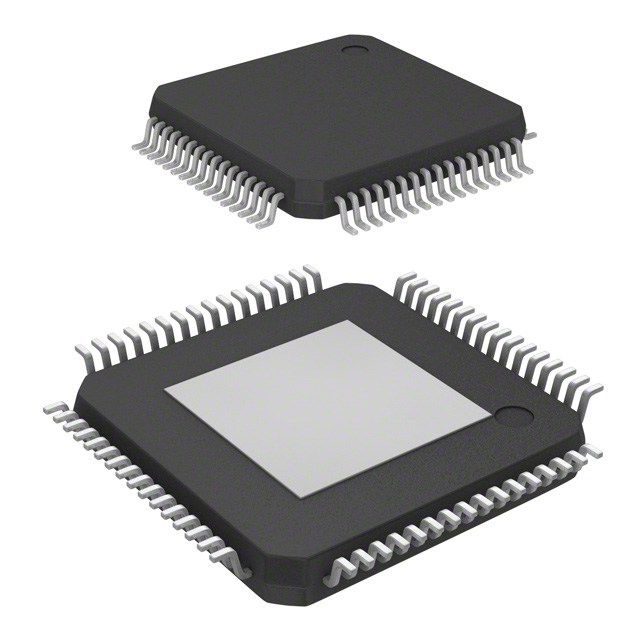
PIN ASSIGNMENT
61
60
59
58
57
56
55
54
53
52
51
50
49
1
2
48
47
3
4
46
45
5
6
7
44
43
IDT82V3358
8
9
10
42
41
40
39
38
11
12
37
36
13
14
35
34
15
16
RST
SCLK
VDDD5
VDDD5
CS
SDI
CLKE
TMS
DGND5
VDDD5
VDDD5
TRST
VDDD5
EX_SYNC3
IN3_CMOS
EX_SYNC2
FRSYNC_8K
MFRSYNC_2K
OUT1_POS
OUT1_NEG
GND_DIFF
VDD_DIFF
IN1_POS
IN1_NEG
IN2_POS
IN2_NEG
NC
EX_SYNC1
IN1_CMOS
IN2_CMOS
DGND4
VDDD4
21
22
23
24
25
26
27
28
29
30
31
32
33
17
18
19
20
AGND
IC1
AGND1
VDDA1
INT_REQ
OSCI
DGND1
VDDD1
VDDD3
DGND3
DGND2
VDDD2
FF_SRCSW
VDDA2
AGND2
IC2
63
62
64
SONET/SDH
IC6
IC5
IC4
IC3
OUT4
AGND3
VDDA3
OUT2
OUT3
VDDD6
DGND6
SDO
TDI
TDO
TCK
1
SYNCHRONOUS ETHERNET WAN PLL
Figure 2. Pin Assignment (Top View)
Pin Assignment
12
May 19, 2009
�IDT82V3358
2
SYNCHRONOUS ETHERNET WAN PLL
PIN DESCRIPTION
Table 1: Pin Description
Name
Pin No.
I/O
Description 1
Type
Global Control Signal
OSCI
6
I
CMOS
FF_SRCSW
13
I
pull-down
CMOS
OSCI: Crystal Oscillator Master Clock
A nominal 12.8000 MHz clock provided by a crystal oscillator is input on this pin. It is the
master clock for the device.
FF_SRCSW: External Fast Selection Enable
During reset, this pin determines the default value of the EXT_SW bit (b4, 0BH)2. The
EXT_SW bit determines whether the External Fast Selection is enabled.
High: The default value of the EXT_SW bit (b4, 0BH) is ‘1’ (External Fast selection is
enabled);
Low: The default value of the EXT_SW bit (b4, 0BH) is ‘0’ (External Fast selection is disabled).
After reset, this pin selects an input clock pair for the T0 DPLL if the External Fast selection is
enabled:
High: Pair IN1_CMOS / IN1_DIFF is selected.
Low: Pair IN2_CMOS / IN2_DIFF is selected.
After reset, the input on this pin takes no effect if the External Fast selection is disabled.
SONET/SDH
64
I
pull-down
CMOS
SONET/SDH: SONET / SDH Frequency Selection
During reset, this pin determines the default value of the IN_SONET_SDH bit (b2, 09H):
High: The default value of the IN_SONET_SDH bit is ‘1’ (SONET);
Low: The default value of the IN_SONET_SDH bit is ‘0’ (SDH).
After reset, the value on this pin takes no effect.
RST
48
I
pull-up
CMOS
RST: Reset
A low pulse of at least 50 µs on this pin resets the device. After this pin is high, the device will
still be held in reset state for 500 ms (typical).
Frame Synchronization Input Signal
EX_SYNC1
28
EX_SYNC2
33
EX_SYNC3
35
I
pull-down
I
pull-down
I
pull-down
CMOS
EX_SYNC1: External Sync Input 1
A 2 kHz, 4 kHz or 8 kHz signal is input on this pin.
CMOS
EX_SYNC2: External Sync Input 2
A 2 kHz, 4 kHz or 8 kHz signal is input on this pin.
CMOS
EX_SYNC3: External Sync Input 3
A 2 kHz, 4 kHz or 8 kHz signal is input on this pin.
Input Clock
IN1_CMOS
29
IN2_CMOS
30
IN1_POS
23
IN1_NEG
24
Pin Description
IN1_CMOS: Input Clock 1
A 2 kHz, 4 kHz, N x 8 kHz 3, 1.544 MHz (SONET) / 2.048 MHz (SDH), 6.48 MHz, 19.44 MHz,
25.92 MHz, 38.88 MHz, 51.84 MHz, 77.76 MHz or 155.52 MHz clock is input on this pin.
IN2_CMOS: Input Clock 2
I
CMOS
A 2 kHz, 4 kHz, N x 8 kHz 3, 1.544 MHz (SONET) / 2.048 MHz (SDH), 6.48 MHz, 19.44 MHz,
pull-down
25.92 MHz, 38.88 MHz, 51.84 MHz, 77.76 MHz or 155.52 MHz clock is input on this pin.
IN1_POS / IN1_NEG: Positive / Negative Input Clock 1
A 2 kHz, 4 kHz, N x 8 kHz 3, 1.544 MHz (SONET) / 2.048 MHz (SDH), 6.48 MHz, 19.44 MHz,
25.92 MHz, 38.88 MHz, 51.84 MHz, 77.76 MHz, 155.52 MHz, 156.25 MHz, 311.04 MHz or
I
PECL/LVDS 622.08 MHz clock is differentially input on this pair of pins. Whether the clock signal is PECL
or LVDS is automatically detected.
Single-ended input for differential input is also supported. Refer to Chapter 8.3.2.3 SingleEnded Input for Differential Input.
I
pull-down
CMOS
13
May 19, 2009
�IDT82V3358
SYNCHRONOUS ETHERNET WAN PLL
Table 1: Pin Description (Continued)
Name
Pin No.
IN2_POS
25
IN2_NEG
26
IN3_CMOS
34
I/O
Description 1
Type
IN2_POS / IN2_NEG: Positive / Negative Input Clock 2
A 2 kHz, 4 kHz, N x 8 kHz 3, 1.544 MHz (SONET) / 2.048 MHz (SDH), 6.48 MHz, 19.44 MHz,
25.92 MHz, 38.88 MHz, 51.84 MHz, 77.76 MHz, 155.52 MHz, 156.25 MHz, 311.04 MHz or
I
PECL/LVDS 622.08 MHz clock is differentially input on this pair of pins. Whether the clock signal is PECL
or LVDS is automatically detected.
Single-ended input for differential input is also supported. Refer to Chapter 8.3.2.3 SingleEnded Input for Differential Input.
IN3_CMOS: Input Clock 3
I
CMOS
A 2 kHz, 4 kHz, N x 8 kHz 3, 1.544 MHz (SONET) / 2.048 MHz (SDH), 6.48 MHz, 19.44 MHz,
pull-down
25.92 MHz, 38.88 MHz, 51.84 MHz, 77.76 MHz or 155.52 MHz clock is input on this pin.
Output Frame Synchronization Signal
FRSYNC_8K
17
O
CMOS
MFRSYNC_2K
18
O
CMOS
FRSYNC_8K: 8 kHz Frame Sync Output
An 8 kHz signal is output on this pin.
MFRSYNC_2K: 2 kHz Multiframe Sync Output
A 2 kHz signal is output on this pin.
Output Clock
OUT1_POS
19
OUT1_NEG
20
OUT2
56
O
OUT3
55
O
OUT4
59
O
O
OUT1_POS / OUT1_NEG: Positive / Negative Output Clock 1
A 1 Hz, 400 Hz, 2 kHz, 8 kHz, 64 kHz, N x E1 4, N x T1 5, N x 13.0 MHz 6, N x 3.84 MHz 7,
PECL/LVDS 5 MHz, 10 MHz, 20 MHz, 25 MHz, E3, T3, 6.48 MHz, 19.44 MHz, 25.92 MHz, 38.88 MHz,
51.84 MHz, 77.76 MHz, 125 MHz, 155.52 MHz, 156.25 MHz, 311.04 MHz, 312.5 MHz or
622.08 MHz clock is differentially output on this pair of pins.
OUT2: Output Clock 2
A 1 Hz, 400 Hz, 2 kHz, 8 kHz, 64 kHz, N x E1 4, N x T1 5, N x 13.0 MHz 6, N x 3.84 MHz 7,
CMOS
5 MHz, 10 MHz, 20 MHz, 25 MHz, E3, T3, 6.48 MHz, 19.44 MHz, 25.92 MHz, 38.88 MHz,
51.84 MHz, 77.76 MHz, 125 MHz, 155.52 MHz, 156.25 MHz or 312.5 MHz clock is output on
this pin.
OUT3: Output Clock 3
A 1 Hz, 400 Hz, 2 kHz, 8 kHz, 64 kHz, N x E1 4, N x T1 5, N x 13.0 MHz 6, N x 3.84 MHz 7,
CMOS
5 MHz, 10 MHz, 20 MHz, E3, T3, 6.48 MHz, 19.44 MHz, 25.92 MHz, 38.88 MHz, 51.84 MHz,
77.76 MHz or 155.52 MHz clock is output on this pin.
OUT4: Output Clock 4
A 1 Hz, 400 Hz, 2 kHz, 8 kHz, 64 kHz, N x E1 4, N x T1 5, N x 13.0 MHz 6, N x 3.84 MHz 7,
CMOS
5 MHz, 10 MHz, 20 MHz, E3, T3, 6.48 MHz, 19.44 MHz, 25.92 MHz, 38.88 MHz, 51.84 MHz,
77.76 MHz or 155.52 MHz clock is output on this pin.
Microprocessor Interface
CS
44
I
pull-up
CMOS
INT_REQ
5
O
CMOS
SDI
43
CMOS
CLKE
42
I
pull-down
Pin Description
CS: Chip Selection
A transition from high to low must occur on this pin for each read or write operation and this
pin should remain low until the operation is over.
INT_REQ: Interrupt Request
This pin is used as an interrupt request. The output characteristics are determined by the
HZ_EN bit (b1, 0CH) and the INT_POL bit (b0, 0CH).
SDI: Serial Data Input
In Serial mode, this pin is used as the serial data input. Address and data on this pin are serially clocked into the device on the rising edge of SCLK.
CLKE: SCLK Active Edge Selection
In Serial mode, this pin selects the active edge of SCLK to update the SDO:
High - The falling edge;
Low - The rising edge.
14
May 19, 2009
�IDT82V3358
SYNCHRONOUS ETHERNET WAN PLL
Table 1: Pin Description (Continued)
Name
Pin No.
I/O
Type
SDO
52
I/O
pull-down
CMOS
SCLK
47
I
pull-down
CMOS
Description 1
SDO: Serial Data Output
In Serial mode, this pin is used as the serial data output. Data on this pin is serially clocked
out of the device on the active edge of SCLK.
SCLK: Shift Clock
In Serial mode, a shift clock is input on this pin.
Data on SDI is sampled by the device on the rising edge of SCLK. Data on SDO is updated
on the active edge of SCLK. The active edge is determined by the CLKE.
JTAG (per IEEE 1149.1)
TRST
37
I
pull-down
CMOS
TMS
41
I
pull-up
CMOS
TCK
49
I
pull-down
CMOS
TDI
51
I
pull-up
CMOS
TDO
50
O
CMOS
TRST: JTAG Test Reset (Active Low)
A low signal on this pin resets the JTAG test port.
This pin should be connected to ground when JTAG is not used.
TMS: JTAG Test Mode Select
The signal on this pin controls the JTAG test performance and is sampled on the rising edge
of TCK.
TCK: JTAG Test Clock
The clock for the JTAG test is input on this pin. TDI and TMS are sampled on the rising edge
of TCK and TDO is updated on the falling edge of TCK.
If TCK is idle at a low level, all stored-state devices contained in the test logic will indefinitely
retain their state.
TDI: JTAG Test Data Input
The test data is input on this pin. It is clocked into the device on the rising edge of TCK.
TDO: JTAG Test Data Output
The test data is output on this pin. It is clocked out of the device on the falling edge of TCK.
TDO pin outputs a high impedance signal except during the process of data scanning.
This pin can indicate the interrupt of T0 selected input clock fail, as determined by the
LOS_FLAG_ON_TDO bit (b6, 0BH). Refer to Chapter 3.8.1 Input Clock Validity for details.
Power & Ground
VDDD1
8
VDDD2
12
VDDD3
9
VDDD4
32
VDDD5
36, 38, 39, 45, 46
VDDD6
VDDA1
54
4
VDDA2
14
Power
-
VDDA3
VDD_DIFF
GND_DIFF
57
22
21
Power
Ground
-
VDDDn: 3.3 V Digital Power Supply
Each VDDDn should be paralleled with ground through a 0.1 µF capacitor.
Power
Pin Description
-
VDDAn: 3.3 V Analog Power Supply
Each VDDAn should be paralleled with ground through a 0.1 µF capacitor.
VDD_DIFF: 3.3 V Power Supply for OUT
GND_DIFF: Ground for OUT1
15
May 19, 2009
�IDT82V3358
SYNCHRONOUS ETHERNET WAN PLL
Table 1: Pin Description (Continued)
Name
Pin No.
I/O
Description 1
Type
Others
IC1
2
IC2
16
IC3
60
IC4
61
IC5
62
IC6
NC
63
27
IC: Internal Connected
Internal Use. These pins should be left open for normal operation.
-
-
-
-
NC: Not Connected
Note:
1. All the unused input pins should be connected to ground; the output of all the unused output pins are don’t-care.
2. The contents in the brackets indicate the position of the register bit/bits.
3. N x 8 kHz: 1 < N < 19440.
4. N x E1: N = 1, 2, 3, 4, 6, 8, 12, 16, 24, 32, 48, 64.
5. N x T1: N = 1, 2, 3, 4, 6, 8, 12, 16, 24, 32, 48, 64, 96.
6. N x 13.0 MHz: N = 1, 2, 4.
7. N x 3.84 MHz: N = 1, 2, 4, 8, 16, 10, 20, 40.
Pin Description
16
May 19, 2009
�IDT82V3358
SYNCHRONOUS ETHERNET WAN PLL
3
FUNCTIONAL DESCRIPTION
3.2
3.1
RESET
A nominal 12.8000 MHz clock, provided by a crystal oscillator, is
input on the OSCI pin. This clock is provided for the device as a master
clock. The master clock is used as a reference clock for all the internal
circuits. A better active edge of the master clock is selected by the
OSC_EDGE bit to improve jitter and wander performance.
The reset operation resets all registers and state machines to their
default value or status.
After power on, the device must be reset for normal operation.
MASTER CLOCK
In fact, an offset from the nominal frequency may input on the OSCI
pin. This offset can be compensated by setting the
NOMINAL_FREQ_VALUE[23:0] bits. The calibration range is within
±741 ppm.
For a complete reset, the RST pin must be asserted low for at least
50 µs. After the RST pin is pulled high, the device will still be in reset
state for 500 ms (typical). If the RST pin is held low continuously, the
device remains in reset state.
The performance of the master clock should meet GR-1244-CORE,
GR-253-CORE, ITU-T G.812 and G.813 criteria.
Table 2: Related Bit / Register in Chapter 3.2
Bit
Register
Address (Hex)
NOMINAL_FREQ_VALUE[23:0]
OSC_EDGE
NOMINAL_FREQ[23:16]_CNFG, NOMINAL_FREQ[15:8]_CNFG, NOMINAL_FREQ[7:0]_CNFG
DIFFERENTIAL_IN_OUT_OSCI_CNFG
06, 05, 04
0A
Functional Description
17
May 19, 2009
�IDT82V3358
3.3
SYNCHRONOUS ETHERNET WAN PLL
INPUT CLOCKS & FRAME SYNC SIGNALS
For SDH and SONET networks, the default frequency is different.
SONET / SDH frequency selection is controlled by the IN_SONET_SDH
bit. During reset, the default value of the IN_SONET_SDH bit is determined by the SONET/SDH pin: high for SONET and low for SDH. After
reset, the input signal on the SONET/SDH pin takes no effect.
Altogether 5 clocks and 3 frame sync signals are input to the device.
3.3.1
INPUT CLOCKS
The device provides 5 input clock ports.
IDT82V3358 supports single-ended input for differential input. Refer
to Chapter 8.3.2.3 Single-Ended Input for Differential Input.
According to the input port technology, the input ports support the following technologies:
• PECL/LVDS
• CMOS
3.3.2
Three 2 kHz, 4 kHz or 8 kHz frame sync signals are input on the
EX_SYNC1 to EX_SYNC3 pins respectively. They are CMOS inputs.
The input frequency should match the setting in the SYNC_FREQ[1:0]
bits.
According to the input clock source, the following clock sources are
supported:
• T1: Recovered clock from STM-N or OC-n
• T2: PDH network synchronization timing
• T3: External synchronization reference timing
Only one of the three frame sync input signals is used for frame sync
output signal synchronization. Refer to Chapter 3.13.2 Frame SYNC
Output Signals for details.
IN1_CMOS ~ IN3_CMOS support CMOS input signal only and the
clock sources can be from T1, T2 or T3.
Table 3: Related Bit / Register in Chapter 3.3
IN1_DIFF and IN2_DIFF support PECL/LVDS input signal and automatically detect whether the signal is PECL or LVDS. The clock sources
can be from T1, T2 or T3.
Functional Description
FRAME SYNC INPUT SIGNALS
18
Bit
Register
Address (Hex)
IN_SONET_SDH
SYNC_FREQ[1:0]
INPUT_MODE_CNFG
09
May 19, 2009
�IDT82V3358
3.4
SYNCHRONOUS ETHERNET WAN PLL
INPUT CLOCK PRE-DIVIDER
Once the division factor is set for the input clock selected by the
PRE_DIV_CH_VALUE[3:0] bits, it is valid until a different division factor
is set for the same input clock. The division factor is calculated as follows:
Each input clock is assigned an internal Pre-Divider. The Pre-Divider
is used to divide the clock frequency down to the DPLL required frequency, which is no more than 38.88 MHz.For each input clock, the
DPLL required frequency is set by the corresponding IN_FREQ[3:0] bits
Division Factor = (the frequency of the clock input to the DivN
Divider ÷ the frequency of the DPLL required clock set by the
IN_FREQ[3:0] bits) - 1
If the input clock is of 2 kHz, 4 kHz or 8 kHz, the Pre-Divider is
bypassed automatically and the corresponding IN_FREQ[3:0] bits
should be set to match the input frequency; the input clock can be
inverted, as determined by the IN_2K_4K_8K_INV bit.
The DivN Divider can only divide the input clock whose frequency is
lower than () 155.52 MHz. The
input clock can be divided by 4, 5 or can bypass the HF Divider, as
determined by the IN1_DIFF_DIV[1:0]/IN2_DIFF_DIV[1:0] bits correspondingly.
The input clock on the IN2_DIFF pin is 622.08 MHz; the DPLL
required clock is 6.48 MHz by programming the IN_FREQ[3:0] bits of
register IN2_DIFF to ‘0010’. Do the following step by step to divide the
input clock:
1. Use the HF Divider to divide the clock down to 155.52 MHz:
622.08 ÷ 155.52 = 4, so set the IN2_DIFF_DIV[1:0] bits to ‘01’;
2. Use the DivN Divider to divide the clock down to 6.48 MHz:
Set the PRE_DIV_CH_VALUE[3:0] bits to ‘0110’;
Set the DIRECT_DIV bit in Register IN2_DIFF_CNFG to ‘1’ and
the LOCK_8K bit in Register IN2_DIFF_CNFG to ‘0’;
155.52 ÷ 6.48 = 24; 24 - 1 = 23, so set the
PRE_DIVN_VALUE[14:0] bits to ‘10111’.
Either the DivN Divider or the Lock 8k Divider can be used or both
can be bypassed, as determined by the DIRECT_DIV bit and the
LOCK_8K bit.
When the DivN Divider is used, the division factor setting should
observe the following order:
1. Select an input clock by the PRE_DIV_CH_VALUE[3:0] bits;
2. Write the lower eight bits of the division factor to the
PRE_DIVN_VALUE[7:0] bits;
3. Write the higher eight bits of the division factor to the
PRE_DIVN_VALUE[14:8] bits.
Pre-Divider
IN1_DIFF_DIV[1:0] bits / IN2_DIFF_DIV[1:0] bits
input clock
HF Divider
(for IN1_DIFF &
IN2_DIFF only)
DIRECT_DIV bit
DivN Divider
LOCK_8K bit
Lock 8k Divider
DPLL required clock
Figure 3. Pre-Divider for An Input Clock
Table 4: Related Bit / Register in Chapter 3.4
Bit
IN1_DIFF_DIV[1:0]
IN2_DIFF_DIV[1:0]
IN_FREQ[3:0]
DIRECT_DIV
LOCK_8K
IN_2K_4K_8K_INV
PRE_DIV_CH_VALUE[3:0]
PRE_DIVN_VALUE[14:0]
Functional Description
Register
Address (Hex)
IN1_DIFF_IN2_DIFF_HF_DIV_CNFG
18
IN1_CMOS_CNFG, IN2_CMOS_CNFG, IN1_DIFF_CNFG, IN2_DIFF_CNFG,
IN3_CNFG
16, 17, 19, 1A, 1D
FR_MFR_SYNC_CNFG
PRE_DIV_CH_CNFG
PRE_DIVN[14:8]_CNFG, PRE_DIVN[7:0]_CNFG
74
23
25, 24
19
May 19, 2009
�IDT82V3358
3.5
SYNCHRONOUS ETHERNET WAN PLL
INPUT CLOCK QUALITY MONITORING
responding BUCKET_SEL[1:0] bits. Each leaky bucket configuration
consists of four elements: upper threshold, lower threshold, bucket size
and decay rate.
The qualities of all the input clocks are always monitored in the following aspects:
• Activity
• Frequency
The bucket size is the capability of the accumulator. If the number of
the accumulated events reach the bucket size, the accumulator will stop
increasing even if further events are detected. The upper threshold is a
point above which a no-activity alarm is raised. The lower threshold is a
point below which the no-activity alarm is cleared. The decay rate is a
certain period during which the accumulator decreases by 1 if no event
is detected.
The qualified clocks are available for T0/T4 DPLL selection. The T0
and T4 selected input clocks have to be monitored further. Refer to
Chapter 3.7 Selected Input Clock Monitoring for details.
3.5.1
ACTIVITY MONITORING
The leaky bucket configuration is programmed by one of four groups
of register bits: the BUCKET_SIZE_n_DATA[7:0] bits, the UPPER_
THRESHOLD_n_DATA[7:0] bits, the LOWER_THRESHOLD_n_
DATA[7:0] bits and the DECAY_RATE_n_DATA[1:0] bits respectively; ‘n’
is 0 ~ 3.
Activity is monitored by using an internal leaky bucket accumulator,
as shown in Figure 4.
Each input clock is assigned an internal leaky bucket accumulator.
The input clock is monitored for each period of 128 ms and the internal
leaky bucket accumulator increases by 1 when an event is detected; it
decreases by 1 if no event is detected within the period set by the decay
rate. The event is that an input clock drifts outside (>) ±500 ppm with
respect to the master clock within a 128 ms period.
The no-activity alarm status of the input clock is indicated by the
INn_CMOS_NO_ACTIVITY_ALARM bit (n = 1, 2, or 3) /
INn_DIFF_NO_ACTIVITY_ALARM bit (n = 1 or 2).
The input clock with a no-activity alarm is disqualified for clock selection for T0/T4 DPLL.
There are four configurations (0 - 3) for a leaky bucket accumulator.
The leaky bucket configuration for an input clock is selected by the cor-
clock signal with events
clock signal with no event
Input Clock
Decay
Rate
Bucket Size
Upper Threshold
Leaky Bucket Accumulator
Lower Threshold
0
No-activity Alarm Indication
Figure 4. Input Clock Activity Monitoring
Functional Description
20
May 19, 2009
�IDT82V3358
3.5.2
SYNCHRONOUS ETHERNET WAN PLL
The input clock with a frequency hard alarm is disqualified for clock
selection for T0/T4 DPLL.
FREQUENCY MONITORING
Frequency is monitored by comparing the input clock with a reference clock. The reference clock can be derived from the master clock or
the output of T0 DPLL, as determined by the FREQ_MON_CLK bit.
In addition, if the input clock is 2 kHz, 4 kHz or 8 kHz, its clock edges
with respect to the reference clock are monitored. If any edge drifts outside ±5%, the input clock is disqualified for clock selection for T0/T4
DPLL. The input clock is qualified if any edge drifts inside ±5%. This
function is supported only when the IN_NOISE_WINDOW bit is ‘1’.
A frequency hard alarm threshold is set for frequency monitoring. If
the FREQ_MON_HARD_EN bit is ‘1’, a frequency hard alarm is raised
when the frequency of the input clock with respect to the reference clock
is above the threshold; the alarm is cleared when the frequency is below
the threshold.
The frequency of each input clock with respect to the reference clock
can be read by doing the following step by step:
1. Select an input clock by setting the IN_FREQ_READ_CH[3:0]
bits;
2. Read the value in the IN_FREQ_VALUE[7:0] bits and calculate
as follows:
The frequency hard alarm threshold can be calculated as follows:
Frequency Hard Alarm Threshold (ppm) = (ALL_FREQ_HARD_
THRESHOLD[3:0] + 1) X FREQ_MON_FACTOR[3:0]
If the FREQ_MON_HARD_EN bit is ‘1’, the frequency hard alarm
status
of
the
input
clock
is
indicated
by
the
INn_CMOS_FREQ_HARD_ALARM bit (n = 1, 2 or 3) /
INn_DIFF_FREQ_HARD_ALARM bit (n = 1 or 2). When the
FREQ_MON_HARD_EN bit is ‘0’, no frequency hard alarm is raised
even if the input clock is above the frequency hard alarm threshold.
Input Clock Frequency (ppm) = IN_FREQ_VALUE[7:0] X
FREQ_MON_FACTOR[3:0]
Note that the value set by the FREQ_MON_FACTOR[3:0] bits
depends on the application.
Table 5: Related Bit / Register in Chapter 3.5
Bit
Register
Address (Hex)
BUCKET_SIZE_n_DATA[7:0] (3 ≥ n ≥ 0)
UPPER_THRESHOLD_n_DATA[7:0] (3 ≥ n ≥ 0)
LOWER_THRESHOLD_n_DATA[7:0] (3 ≥ n ≥ 0)
DECAY_RATE_n_DATA[1:0] (3 ≥ n ≥ 0)
BUCKET_SIZE_0_CNFG ~ BUCKET_SIZE_3_CNFG
UPPER_THRESHOLD_0_CNFG ~ UPPER_THRESHOLD_3_CNFG
LOWER_THRESHOLD_0_CNFG ~ LOWER_THRESHOLD_3_CNFG
DECAY_RATE_0_CNFG ~ DECAY_RATE_3_CNFG
IN1_CMOS_CNFG, IN2_CMOS_CNFG, IN1_DIFF_CNFG,
IN2_DIFF_CNFG, IN3_CMOS_CNFG
33, 37, 3B, 3F
31, 35, 39, 3D
32, 36, 3A, 3E
34, 38, 3C, 40
BUCKET_SEL[1:0]
INn_CMOS_NO_ACTIVITY_ALARM (n = 1, 2, or 3)
INn_CMOS_FREQ_HARD_ALARM (n = 1, 2 or 3)
INn_DIFF_NO_ACTIVITY_ALARM (n = 1 or 2)
INn_DIFF_FREQ_HARD_ALARM (n = 1 or 2)
FREQ_MON_CLK
FREQ_MON_HARD_EN
ALL_FREQ_HARD_THRESHOLD[3:0]
FREQ_MON_FACTOR[3:0]
IN_NOISE_WINDOW
IN_FREQ_READ_CH[3:0]
IN_FREQ_VALUE[7:0]
Functional Description
16, 17, 19, 1A, 1D
IN1_IN2_CMOS_STS, IN3_CMOS_STS
44, 47
IN1_IN2_DIFF_STS
45
MON_SW_PBO_CNFG
0B
ALL_FREQ_MON_THRESHOLD_CNFG
FREQ_MON_FACTOR_CNFG
PHASE_MON_PBO_CNFG
IN_FREQ_READ_CH_CNFG
IN_FREQ_READ_STS
2F
2E
78
41
42
21
May 19, 2009
�IDT82V3358
3.6
SYNCHRONOUS ETHERNET WAN PLL
T0 / T4 DPLL INPUT CLOCK SELECTION
Automatic selection is done based on the results of input clocks quality monitoring and the related registers configuration.
An input clock is selected for T0 DPLL and for T4 DPLL respectively.
The selected input clock is attempted to be locked in T0/T4 DPLL.
For T0 path, the EXT_SW bit and the T0_INPUT_SEL[3:0] bits determine the input clock selection, as shown in Table 6:
3.6.1
The External Fast selection is supported by T0 path only. In External
Fast selection, only IN1_CMOS/IN1_DIFF and IN2_CMOS/IN2_DIFF
pairs are available for selection. Refer to Figure 5. The results of input
clocks quality monitoring (refer to Chapter 3.5 Input Clock Quality Monitoring) do not affect input clock selection.
Table 6: Input Clock Selection for T0 Path
Control Bits
EXT_SW
T0_INPUT_SEL[3:0]
1
don’t-care
other than 0000
0000
0
EXTERNAL FAST SELECTION (T0 ONLY)
Input Clock Selection
External Fast selection
Forced selection
Automatic selection
The T0 input clock selection is determined by the FF_SRCSW pin
after reset (this pin determines the default value of the EXT_SW bit during reset, refer to Chapter 2 Pin Description), the
IN1_CMOS_SEL_PRIORITY[3:0]
bits
and
the
IN2_CMOS_SEL_PRIORITY[3:0] bits, as shown in Figure 5 and
Table 8:
For T4 path, the T4 DPLL may lock to a T0 DPLL output or lock independently from T0 path, as determined by the T4_LOCK_T0 bit. When
the T4 DPLL locks to the T0 DPLL output, the T4 selected input clock is
a 77.76 MHz or 8 kHz signal from the T0 DPLL 77.76 MHz path (refer to
Chapter 3.11.5.1 T0 Path), as determined by the T0_FOR_T4 bit. When
the T4 path locks independently from the T0 path, the T4 DPLL input
clock selection is determined by the T4_INPUT_SEL[3:0] bits. Refer to
Table 7:
IN1_CMOS_SEL_PRIORITY[3:0] bits
IN1_CMOS
FF_SRCSW pin
IN1_DIFF
Table 7: Input Clock Selection for T4 Path
Control Bits - T4_INPUT_SEL[3:0]
Input Clock Selection
other than 0000
0000
Forced selection
Automatic selection
attempted to be
locked in T0 DPLL
IN2_CMOS
IN2_DIFF
External Fast selection is done between IN1_CMOS/IN1_DIFF and
IN2_CMOS/IN2_DIFF pairs.
IN2_CMOS_SEL_PRIORITY[3:0] bits
Forced selection is done by setting the related registers.
Figure 5. External Fast Selection
Table 8: External Fast Selection
Control Pin & Bits
FF_SRCSW (after reset)
IN1_CMOS_SEL_PRIORITY[3:0]
IN2_CMOS_SEL_PRIORITY[3:0]
high
0000
other than 0000
don’t-care
low
don’t-care
0000
other than 0000
Functional Description
22
the Selected Input Clock
IN1_DIFF
IN1_CMOS
IN2_DIFF
IN2_CMOS
May 19, 2009
�IDT82V3358
3.6.2
SYNCHRONOUS ETHERNET WAN PLL
INn_DIFF_SEL_PRIORITY[3:0] bits (n = 1 or 2). If more than one qualified input clock is available and has the same priority, the input clock
with the smallest ‘n’ is selected. See Table 9 for the ‘n’ assigned to the
input clock.
FORCED SELECTION
In Forced selection, the selected input clock is set by the
T0_INPUT_SEL[3:0] / T4_INPUT_SEL[3:0] bits. The results of input
clocks quality monitoring (refer to Chapter 3.5 Input Clock Quality Monitoring) do not affect the input clock selection.
3.6.3
Table 9: ‘n’ Assigned to the Input Clock
AUTOMATIC SELECTION
In Automatic selection, the input clock selection is determined by its
validity and priority. The validity depends on the results of input clock
quality monitoring (refer to Chapter 3.5 Input Clock Quality Monitoring).
In all the qualified input clocks, the one with the highest priority is
selected. The priority is configured by the corresponding
INn_CMOS_SEL_PRIORITY[3:0] bits (n = 1, 2 or 3) / the
Input Clock
‘n’ Assigned to the Input Clock
IN1_CMOS
IN1_DIFF
IN2_CMOS
IN2_DIFF
IN3_CMOS
1
2
3
4
5
Table 10: Related Bit / Register in Chapter 3.6
Bit
Register
Address (Hex)
EXT_SW
T0_INPUT_SEL[3:0]
T4_LOCK_T0
T0_FOR_T4
T4_INPUT_SEL[3:0]
MON_SW_PBO_CNFG
T0_INPUT_SEL_CNFG
0B
50
T4_INPUT_SEL_CNFG
51
IN1_IN2_CMOS_SEL_PRIORITY_CNFG,
IN3_CMOS_SEL_PRIORITY_CNFG
IN1_IN2_DIFF_SEL_PRIORITY_CNFG
T4_T0_REG_SEL_CNFG
INn_CMOS_SEL_PRIORITY[3:0] (n = 1, 2 or 3)
INn_DIFF_SEL_PRIORITY[3:0] (n = 1 or 2)
T4_T0_SEL
27 *, 2A *
28 *
07
Note: * The setting in the 27, 28 and 2A registers is either for T0 path or for T4 path, as determined by the T4_T0_SEL bit.
Functional Description
23
May 19, 2009
�IDT82V3358
3.7
SYNCHRONOUS ETHERNET WAN PLL
SELECTED INPUT CLOCK MONITORING
3.7.1.3
The T0/T4 DPLL compares the selected input clock with the feedback signal. If the phase-compared result exceeds the fine phase limit
programmed by the PH_LOS_FINE_LIMT[2:0] bits, a fine phase loss is
triggered. It is cleared once the phase-compared result is within the fine
phase limit.
The quality of the selected input clock is always monitored (refer to
Chapter 3.5 Input Clock Quality Monitoring) and the DPLL locking status
is always monitored.
3.7.1
T0 / T4 DPLL LOCKING DETECTION
The following events is always monitored:
• Fast Loss;
• Coarse Phase Loss;
• Fine Phase Loss;
• Hard Limit Exceeding.
3.7.1.1
The occurrence of the fine phase loss will result in T0/T4 DPLL
unlocked if the FINE_PH_LOS_LIMT_EN bit is ‘1’.
3.7.1.4
A fast loss is triggered when the selected input clock misses 2 consecutive clock cycles. It is cleared once an active clock edge is detected.
For T0 path, the occurrence of the fast loss will result in T0 DPLL
unlocked if the FAST_LOS_SW bit is ‘1’. For T4 path, the occurrence of
the fast loss will result in T4 DPLL unlocked regardless of the
FAST_LOS_SW bit.
Coarse Phase Loss
The DPLL soft limit is set by the DPLL_FREQ_SOFT_LIMT[6:0] bits
and can be calculated as follows:
The T0/T4 DPLL compares the selected input clock with the feedback signal. If the phase-compared result exceeds the coarse phase
limit, a coarse phase loss is triggered. It is cleared once the phase-compared result is within the coarse phase limit.
DPLL Soft Limit (ppm) = DPLL_FREQ_SOFT_LIMT[6:0] X 0.724
The DPLL hard limit is set by the DPLL_FREQ_HARD_LIMT[15:0]
bits and can be calculated as follows:
When the selected input clock is of 2 kHz, 4 kHz or 8 kHz, the coarse
phase limit depends on the MULTI_PH_8K_4K_2K_EN bit, the
WIDE_EN bit and the PH_LOS_COARSE_LIMT[3:0] bits. Refer to
Table 11. When the selected input clock is of other frequencies but 2
kHz, 4 kHz and 8 kHz, the coarse phase limit depends on the WIDE_EN
bit and the PH_LOS_COARSE_LIMT[3:0] bits. Refer to Table 12.
DPLL Hard Limit (ppm) = DPLL_FREQ_HARD_LIMT[15:0] X 0.0014
3.7.2
0
Coarse Phase Limit
don’t-care
±1 UI
0
±1 UI
1
set by the PH_LOS_COARSE_LIMT[3:0] bits
1
If the FAST_LOS_SW bit, the COARSE_PH_LOS_LIMT_EN bit, the
FINE_PH_LOS_LIMT_EN bit or the FREQ_LIMT_PH_LOS bit is ‘0’, the
DPLL locking status will not be affected even if the corresponding event
is triggered. If all these bits are ‘0’, the DPLL will be in locked state in 2
seconds.
Table 12: Coarse Phase Limit Programming (the selected input
clock of other than 2 kHz, 4 kHz and 8 kHz)
WIDE_EN
Coarse Phase Limit
0
1
±1 UI
set by the PH_LOS_COARSE_LIMT[3:0] bits
The DPLL locking status is indicated by the T0_DPLL_LOCK /
T4_DPLL_LOCK bit.
The T4_STS 1 bit will be set when the locking status of the T4 DPLL
changes (from ‘lock’ to ‘unlock’ or from ‘unlock’ to ‘lock’). If the T4_STS 2
bit is ‘1’, an interrupt will be generated.
The occurrence of the coarse phase loss will result in T0/T4 DPLL
unlocked if the COARSE_PH_LOS_LIMT_EN bit is ‘1’.
Functional Description
LOCKING STATUS
The DPLL locking status depends on the locking monitoring results.
The DPLL is in locked state if none of the following events is triggered
during 2 seconds; otherwise, the DPLL is unlocked.
• Fast Loss (the FAST_LOS_SW bit is ‘1’);
• Coarse Phase Loss (the COARSE_PH_LOS_LIMT_EN bit is
‘1’);
• Fine Phase Loss (the FINE_PH_LOS_LIMT_EN bit is ‘1’);
• DPLL Hard Alarm (the FREQ_LIMT_PH_LOS bit is ‘1’).
Table 11: Coarse Phase Limit Programming (the selected input
clock of 2 kHz, 4 kHz or 8 kHz)
MULTI_PH_8K_4K
WIDE_EN
_2K_EN
Hard Limit Exceeding
Two limits are available for this monitoring. They are DPLL soft limit
and DPLL hard limit. When the frequency of the DPLL output with
respect to the master clock exceeds the DPLL soft / hard limit, a DPLL
soft / hard alarm will be raised; the alarm is cleared once the frequency
is within the corresponding limit. The occurrence of the DPLL soft alarm
does not affect the T0/T4 DPLL locking status. The DPLL soft alarm is
indicated by the corresponding T0_DPLL_SOFT_FREQ_ALARM /
T4_DPLL_SOFT_FREQ_ALARM bit. The occurrence of the DPLL hard
alarm will result in T0/T4 DPLL unlocked if the FREQ_LIMT_PH_LOS bit
is ‘1’.
Fast Loss
3.7.1.2
Fine Phase Loss
24
May 19, 2009
�IDT82V3358
3.7.3
SYNCHRONOUS ETHERNET WAN PLL
• Be cleared when a ‘1’ is written to the corresponding
INn_CMOS_PH_LOCK_ALARM
/
INn_DIFF_PH_LOCK_
ALARM bit;
• Be cleared after the period (= TIME_OUT_VALUE[5:0] X
MULTI_FACTOR[1:0] in second) which starts from when the
alarm is raised.
PHASE LOCK ALARM (T0 ONLY)
A phase lock alarm will be raised when the selected input clock can
not be locked in T0 DPLL within a certain period. This period can be calculated as follows:
Period (sec.) = TIME_OUT_VALUE[5:0] X MULTI_FACTOR[1:0]
The phase lock alarm is indicated by the corresponding
INn_CMOS_PH_LOCK_ALARM bit (n = 1, 2 or 3) /
INn_DIFF_PH_LOCK_ALARM bit (n = 1 or 2).
The selected input clock with a phase lock alarm is disqualified for T0
DPLL locking.
Note that no phase lock alarm is raised if the T4 selected input clock
can not be locked.
The phase lock alarm can be cleared by the following two ways, as
selected by the PH_ALARM_TIMEOUT bit:
Table 13: Related Bit / Register in Chapter 3.7
Bit
Register
Address (Hex)
PHASE_LOSS_FINE_LIMIT_CNFG
5B *
PHASE_LOSS_COARSE_LIMIT_CNFG
5A *
OPERATING_STS
52
DPLL_FREQ_SOFT_LIMIT_CNFG
65
DPLL_FREQ_HARD_LIMT[15:0]
DPLL_FREQ_HARD_LIMIT[15:8]_CNFG,
DPLL_FREQ_HARD_LIMIT[7:0]_CNFG
67, 66
T4_STS 1
INTERRUPTS3_STS
0F
INTERRUPTS3_ENABLE_CNFG
12
PHASE_ALARM_TIME_OUT_CNFG
08
IN1_IN2_CMOS_STS, IN3_CMOS_STS
IN1_IN2_DIFF_STS
INPUT_MODE_CNFG
T4_T0_REG_SEL_CNFG
44, 47
45
09
07
FAST_LOS_SW
PH_LOS_FINE_LIMT[2:0]
FINE_PH_LOS_LIMT_EN
MULTI_PH_8K_4K_2K_EN
WIDE_EN
PH_LOS_COARSE_LIMT[3:0]
COARSE_PH_LOS_LIMT_EN
T0_DPLL_SOFT_FREQ_ALARM
T4_DPLL_SOFT_FREQ_ALARM
T0_DPLL_LOCK
T4_DPLL_LOCK
DPLL_FREQ_SOFT_LIMT[6:0]
FREQ_LIMT_PH_LOS
2
T4_STS
TIME_OUT_VALUE[5:0]
MULTI_FACTOR[1:0]
INn_CMOS_PH_LOCK_ALARM (n = 1, 2, or 3)
INn_DIFF_PH_LOCK_ALARM (n = 1 or 2)
PH_ALARM_TIMEOUT
T4_T0_SEL
Note: * The setting in the 5A and 5B registers is either for T0 path or for T4 path, as determined by the T4_T0_SEL bit.
Functional Description
25
May 19, 2009
�IDT82V3358
3.8
SYNCHRONOUS ETHERNET WAN PLL
SELECTED INPUT CLOCK SWITCH
3.8.2
When the device is configured as Automatic input clock selection, T0
input clock switch is different from T4 input clock switch.
If the input clock is selected by External Fast selection or by Forced
selection, it can be switched by setting the related registers (refer to
Chapter 3.6.1 External Fast Selection (T0 only) & Chapter 3.6.2 Forced
Selection) any time. In this case, whether the input clock is qualified for
DPLL locking does not affect the clock switch. If the T4 selected input
clock is a T0 DPLL output, it can only be switched by setting the
T0_FOR_T4 bit.
For T0 path, Revertive and Non-Revertive switches are supported,
as selected by the REVERTIVE_MODE bit.
For T4 path, only Revertive switch is supported.
The difference between Revertive and Non-Revertive switches is
that whether the selected input clock is switched when another qualified
input clock with a higher priority than the current selected input clock is
available for selection. In Non-Revertive switch, input clock switch is
minimized.
When the input clock is selected by Automatic selection, the input
clock switch depends on its validity and priority. If the current selected
input clock is disqualified, a new qualified input clock may be switched
to.
3.8.1
Conditions of the qualified input clocks available for T0 selection are
different from that for T4 selection, as shown in Table 14:
INPUT CLOCK VALIDITY
For all the input clocks, the validity depends on the results of input
clock quality monitoring (refer to Chapter 3.5 Input Clock Quality Monitoring). When all of the following conditions are satisfied, the input clock
is valid; otherwise, it is invalid.
• No no-activity alarm (the INn_CMOS_NO_ACTIVITY_ALARM /
INn_DIFF_NO_ACTIVITY_ALARM bit is ‘0’);
• No frequency hard alarm (the INn_CMOS_FREQ_HARD_
ALARM / INn_DIFF_FREQ_HARD_ALARM bit is ‘0’);
• If the IN_NOISE_WINDOW bit is ‘1’, all the edges of the input
clock of 2 kHz, 4 kHz or 8 kHz drift inside ±5%; if the
IN_NOISE_WINDOW bit is ‘0’, this condition is ignored.
Table 14: Conditions of Qualified Input Clocks Available for T0 & T4
Selection
Conditions of Qualified Input Clocks Available for T0 & T4 Selection
• Valid, i.e., the INn_CMOS 1 / INn_DIFF 1 bit is ‘1’;
T0 • Priority enabled, i.e., the corresponding INn_CMOS_SEL
_PRIORITY[3:0] / INn_DIFF_SEL_PRIORITY[3:0] bits are not ‘0000’
• Valid (all the validity conditions listed in Chapter 3.8.1 Input Clock Validity are satisfied);
T4
• Priority enabled, i.e., the corresponding INn_CMOS_SEL
_PRIORITY[3:0] / INn_DIFF_SEL_PRIORITY[3:0] bits are not ‘0000’
The validity qualification of the T0 selected input clock is different
from that of the T4 selected input clock. The validity qualification of the
T4 selected input clock is the same as the above. The T0 selected input
clock is valid when all of the above and the following conditions are satisfied; otherwise, it is invalid.
• No phase lock alarm, i.e., the INn_CMOS_PH_LOCK_ALARM /
INn_DIFF_PH_LOCK_ALARM bit is ‘0’;
• If the ULTR_FAST_SW bit is ‘1’, the T0 selected input clock
misses less than (