8701
Low Skew, ÷1, ÷2
LVCMOS/LVTTL Clock Generator
DATASHEET
GENERAL DESCRIPTION
FEATURES
The 8701 is a low skew, ÷1, ÷2 LVCMOS/LVTTL Clock
Generator . The low impedance LVCMOS outputs are
designed to drive 50Ω series or parallel ter minated
transmission lines. The effective fanout can be increased from
20 to 40 by utilizing the ability of the outputs to drive two series
terminated lines.
• Twenty LVCMOS outputs, 7Ω typical output impedance
• One LVCMOS/LVTTL clock input
• Maximum output frequency: 250MHz
• Bank enable logic allows unused banks to be disabled
in reduced fanout applications
The divide select inputs, DIV_SELx, control the output
frequency of each bank. The outputs can be utilized in
the ÷1, ÷2 or a combination of ÷1 and ÷2 modes. The
bank enable inputs, BANK_EN0:1, support enabling and
disabling each bank of outputs individually. The master
reset input, nMR/OE, resets the internal frequency dividers and
also controls the active and high impedance states of all outputs.
• Output skew: 250ps (maximum)
• Part-to-part skew: 600ps (maximum)
• Bank skew: 200ps (maximum)
• Multiple frequency skew: 300ps (maximum)
• 3.3V or mixed 3.3V input, 2.5V output operating
supply modes
The 8701 is character ized at 3.3V and mixed
3.3V input supply, and 2.5V output supply operating
modes. Guaranteed bank, output and part-to-part skew
characteristics make the 8701 ideal for those clock
d i s t r i bu t i o n a p p l i c a t i o n s d e m a n d i n g w e l l d e f i n e d
performance and repeatability.
• 0°C to 70°C ambient operating temperature
• Other divide values available on request
• Available in lead-free RoHS compliant package
BLOCK DIAGRAM
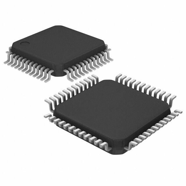
PIN ASSIGNMENT
48-Pin LQFP
7mm x 7mm x 1.4mm
Y Package
Top View
8701 REVISION F JANUARY 21, 2015
1
©2015 Integrated Device Technology, Inc.
�8701 DATA SHEET
TABLE 1. PIN DESCRIPTIONS
Number
2, 5, 11,
26, 32, 35, 41,
44
7, 9, 18, 21,
28, 30, 37, 39,
46, 48
16, 20
25, 27, 29,
31, 33
34, 36, 38,
40, 42
43, 45, 47,
1, 3
4, 6, 8,
10, 12
22
Name
Type
Description
VDDO
Power
Output supply pins.
GND
Power
Power supply ground.
VDD
QA0, QA1, QA2,
QA3, QA4
QB0, QB1, QB2,
QB3, QB4
QC0, QC1, QC2,
QC3, QC4
QD0, QD1, QD2,
QD3, QD4
CLK
Power
Positive supply pins.
Bank A outputs.LVCMOS / LVTTLinterface levels.
Output
7Ω typical output impedance.
Bank B outputs.LVCMOS / LVTTLinterface levels.
Output
7Ω typical output impedance.
Bank C outputs.LVCMOS / LVTTLinterface levels.
Output
7Ω typical output impedance.
Bank D outputs. LVCMOS / LVTTLinterface levels.
Output
7Ω typical output impedance.
Input Pulldown LVCMOS / LVTTL clock input.
Controls frequency division for Bank D outputs.
13
DIV_SELD
Input
Pullup
LVCMOS / LVTTLinterface levels.
Controls frequency division for Bank C outputs.
14
DIV_SELC
Input
Pullup
LVCMOS / LVTTLinterface levels.
Controls frequency division for Bank B outputs.
23
DIV_SELB
Input
Pullup
LVCMOS / LVTTLinterface levels.
Controls frequency division for Bank A outputs.
24
DIV_SELA
Input
Pullup
LVCMOS / LVTTLinterface levels.
BANK_EN1,
Enables and disables outputs by banks.
Input
Pullup
17, 19
LVCMOS / LVTTLinterface levels.
BANK_EN0
Master Reset and output enable. When HIGH, output drivers are
15
nMR/OE
Input
Pullup enabled. Whe LOW, output drivers are in HiZ and dividers are reset.
LVCMOS / LVTTLinterface levels.
NOTE: Pullup and Pulldown refer to internal input resistors. See Table 2, Pin Characteristics, for typical values.
LOW SKEW, ÷1, ÷2
LVCMOS/LVTTL CLOCK GENERATOR
2
REVISION F 1/21/15
�8701 DATA SHEET
TABLE 2. PIN CHARACTERISTICS
Symbol
Parameter
CIN
Input Capacitance
Test Conditions
Minimum
Typical
4
Maximum
pF
RPULLUP
Input Pullup Resistor
51
kΩ
RPULLDOWN
51
kΩ
CPD
Input Pulldown Resistor
Power Dissipation Capacitance
(per output)
ROUT
Output Impedance
VDD, VDDO = 3.465V
Units
15
pF
Ω
7
TABLE 3. FUNCTION TABLE
nMR/OE
0
BANK_EN1
X
1
0
1
1
1
1
Inputs
BANK_EN0
X
QA0:QA4
Hi Z
0
0
Active
Hi Z
Hi Z
Hi Z
fIN/2
0
0
Active
Active
Hi Z
Hi Z
fIN/2
0
1
0
Active
Active
Active
Hi Z
fIN/2
1
1
0
Active
Active
Active
Active
fIN/2
1
0
0
1
Active
Hi Z
Hi Z
Hi Z
fIN
1
1
0
1
Active
Active
Hi Z
Hi Z
fIN
1
0
1
1
Active
Active
Active
Hi Z
fIN
1
1
1
1
Active
Active
Active
Active
fIN
REVISION F 1/21/15
3
QB0:QB4
Hi Z
Outputs
QC0:QC4 QD0:QD4
Hi Z
Hi Z
DIV_SELx
X
Qx Frequency
zero
LOW SKEW, ÷1, ÷2
LVCMOS/LVTTL CLOCK GENERATOR
�8701 DATA SHEET
ABSOLUTE MAXIMUM RATINGS
Supply Voltage, VDD
4.6V
Inputs, VI
-0.5V to VDD + 0.5 V
Outputs, VO
-0.5V to VDDO + 0.5V
Package Thermal Impedance, θJA
47.9°C/W (0 lfpm)
Storage Temperature, TSTG
-65°C to 150°C
NOTE: Stresses beyond those listed under Absolute
Maximum Ratings may cause permanent damage to the
device. These ratings are stress specifications only. Functional
operation of product at these conditions or any conditions
beyond those listed in the DC Characteristics or AC Characteristics is not implied. Exposure to absolute maximum rating
conditions for extended periods may affect product reliability.
TABLE 4A. POWER SUPPLY DC CHARACTERISTICS, VDD = 3.3V±5%, VDDO = 3.3V±5% OR 2.5V±5%, TA = 0°C TO 70°C
Symbol
VDD
Parameter
Positive Supply Voltage
VDDO
Output Supply Voltage
IDD
Power Supply Current
LOW SKEW, ÷1, ÷2
LVCMOS/LVTTL CLOCK GENERATOR
Test Conditions
4
Minimum
3.135
3.135
Typical
3.3
3.3
Maximum
3.465
3.465
Units
V
V
2.375
2.5
2.625
V
95
mA
REVISION F 1/21/15
�8701 DATA SHEET
TABLE 4B. LVCMOS DC CHARACTERISTICS, VDD = 3.3V±5%, VDDO = 3.3V±5% OR 2.5V±5%, TA = 0°C TO 70°C
Symbol
VIH
VIL
IIH
Parameter
Test Conditions
Input
High Voltage
Input
Low Voltage
Input
High Current
Input
Low Current
VOH
VOL
REVISION F 1/21/15
Typical
Maximum
Units
DIV_SELA, DIV_SELB,
DIV_SELC, DIV_SELD,
BANK_EN0, BANK_EN1,
nMR/OE
2
VDD + 0.3
V
CLK
2
VDD + 0.3
V
DIV_SELA, DIV_SELB,
DIV_SELC, DIV_SELD,
BANK_EN0, BANK_EN1,
nMR/OE
-0.3
0.8
V
CLK
-0.3
1.3
V
VDD = VIN = 3.465V
5
µA
VDD = VIN = 3.465V
150
µA
DIV_SELA, DIV_SELB,
DIV_SELC, DIV_SELD,
BANK_EN0, BANK_EN1,
nMR/OE
CLK
IIL
Minimum
DIV_SELA, DIV_SELB,
DIV_SELC, DIV_SELD,
BANK_EN0, BANK_EN1,
nMR/OE
VDD = 3.465V, VIN = 0V
-150
µA
CLK
VDD = 3.465V, VIN = 0V
-5
µA
VDD = VDDO = 3.135V
IOH = -36mA
2.6
V
VDD = 3.135V,
VDDO = 2.375
IOH = -27mA
1.8
V
Output High Voltage
Output Low Voltage
VDD = VDDO = 3.135V
IOL = 36mA
0.5
V
VDD = 3.135V,
VDDO = 2.375
IOL = 27mA
0.5
V
5
LOW SKEW, ÷1, ÷2
LVCMOS/LVTTL CLOCK GENERATOR
�8701 DATA SHEET
TABLE 5A. AC CHARACTERISTICS, VDD = VDDO = 3.3V±5%, TA =0°C TO 70°C
Symbol
Parameter
fMAX
Output Frequency
Test Conditions
f ≤ 200MHz
Minimum
Typical
Maximum
Units
250
MHz
tPD
Propagation Delay; NOTE 1
3.4
ns
tsk(b)
Bank Skew; NOTE 2, 7
Measured on rising edge atVDDO/2
200
ps
tsk(o)
Output Skew; NOTE 3, 7
Measured on rising edge atVDDO/2
250
ps
tsk(w)
Multiple Frequency Skew;
NOTE 4, 7
Measured on rising edge atVDDO/2
300
ps
tsk(pp)
Part-to-Part Skew; NOTE 5, 7
Measured on rising edge atVDDO/2
600
ps
tR
Output Rise Time; NOTE 6
30% to 70%
850
ps
tF
Output Fall Time; NOTE 6
30% to 70%
280
850
ps
f ≤ 200MHz
tCYCLE/2
- 0.5
2
tCYCLE/2
+ 0.5
3
odc
Output Duty Cycle
2.2
280
tCYCLE/2
f = 200MHz
2.5
Output Enable Time;
f = 10MHz
6
tEN
NOTE 6
Output Disable Time;
f = 10MHz
6
tDIS
NOTE 6
All parameters measured at 200MHz unless noted otherwise.
NOTE 1: Measured from the VDD/2 of the input to VDDO/2 of the output.
NOTE 2: Defined as skew within a bank of outputs at the same supply voltages and with equal load conditions.
NOTE 3: Defined as skew between outputs at the same supply voltage and with equal load conditions.
Measured at VDDO/2.
NOTE 4: Defined as skew across banks of outputs operating at different frequency with the same supply voltages
and equal load conditions.
NOTE 5: Defined as skew between outputs on different devices operating at the same supply voltages and
with equal load conditions. Using the same type of inputs on each device, the outputs are measured at VDDO/2.
NOTE 6: These parameters are guaranteed by characterization. Not tested in production.
NOTE 7: This parameter is defined in accordance with JEDEC Standard 65.
ns
ns
ns
ns
TABLE 5B. AC CHARACTERISTICS, VDD = 3.3V±5%, VDDO = 2.5V±5%, TA = 0°C TO 70°C
Symbol
Parameter
fMAX
Output Frequency
tPD
Propagation Delay; NOTE 1
tsk(b)
Bank Skew; NOTE 2, 7
Measured on rising edge atVDDO/2
tsk(o)
Output Skew; NOTE 3, 7
Measured on rising edge atVDDO/2
250
ps
tsk(w)
Multiple Frequency Skew;
NOTE 4, 7
Measured on rising edge atVDDO/2
300
ps
tsk(pp)
Part-to-Part Skew; NOTE 5, 7
Measured on rising edge atVDDO/2
600
ps
tR
Output Rise Time; NOTE 6
30% to 70%
850
ps
tF
Output Fall Time; NOTE 6
30% to 70%
280
850
ps
f ≤ 200MHz
tCYCLE/2
- 0.5
2
tCYCLE/2
+ 0.5
3
odc
Output Duty Cycle
Test Conditions
f ≤ 200MHz
f = 200MHz
Output Enable Time;
tEN
NOTE 6
Output Disable Time;
tDIS
NOTE 6
For notes, please see T5A above.
LOW SKEW, ÷1, ÷2
LVCMOS/LVTTL CLOCK GENERATOR
Minimum
Typical
2.6
280
tCYCLE/2
2.5
Maximum
Units
250
MHz
3.6
ns
225
ps
ns
ns
f = 10MHz
6
ns
f = 10MHz
6
ns
6
REVISION F 1/21/15
�8701 DATA SHEET
PARAMETER MEASUREMENT INFORMATION
3.3V CORE/3.3V OUTPUT LOAD AC TEST CIRCUIT
3.3V CORE/2.5V OUTPUT LOAD AC TEST CIRCUIT
OUTPUT SKEW
PART-TO-PART SKEW
BANK SKEW (where X denotes outputs in the same bank)
PROPAGATION DELAY
OUTPUT DUTY CYCLE/PULSE WIDTH/PERIIOD
OUTPUT RISE/FALL TIME
REVISION F 1/21/15
7
LOW SKEW, ÷1, ÷2
LVCMOS/LVTTL CLOCK GENERATOR
�8701 DATA SHEET
APPLICATION INFORMATION
Driver Termination
For LVCMOS Output Termination, please refer to a separate
Application Note: LVCMOS Driver Termination.
RECOMMENDATIONS FOR UNUSED INPUT AND OUTPUT PINS
INPUTS:
OUTPUTS:
LVCMOS CONTROL PINS:
All control pins have internal pull-ups or pull-downs; additional
resistance is not required but can be added for additional
protection. A 1kΩ resistor can be used.
LVCMOS OUTPUT:
All unused LVCMOS output can be left floating. We recommend
that there is no trace attached.
POWER CONSIDERATIONS
For Power Dissipation, please refer to a separate Application
Note: Power Dissipation for LVCMOS Buffer.
LOW SKEW, ÷1, ÷2
LVCMOS/LVTTL CLOCK GENERATOR
8
REVISION F 1/21/15
�8701 DATA SHEET
RELIABILITY INFORMATION
TABLE 6. θJAVS. AIR FLOW TABLE FOR 48 LEAD LQFP
θJA by Velocity (Linear Feet per Minute)
0
Single-Layer PCB, JEDEC Standard Test Boards
Multi-Layer PCB, JEDEC Standard Test Boards
67.8°C/W
47.9°C/W
200
500
55.9°C/W
42.1°C/W
50.1°C/W
39.4°C/W
NOTE: Most modern PCB designs use multi-layered boards. The data in the second row pertains to most designs.
TRANSISTOR COUNT
The transistor count for 8701 is: 1743
REVISION F 1/21/15
9
LOW SKEW, ÷1, ÷2
LVCMOS/LVTTL CLOCK GENERATOR
�8701 DATA SHEET
PACKAGE OUTLINE - Y SUFFIX FOR 48 LEAD LQFP
TABLE 7. PACKAGE DIMENSIONS
JEDEC VARIATION
ALL DIMENSIONS IN MILLIMETERS
SYMBOL
BBC
MINIMUM
NOMINAL
N
MAXIMUM
48
A
--
--
1.60
A1
0.05
--
0.15
A2
1.35
1.40
1.45
b
0.17
0.22
0.27
c
0.09
--
0.20
D
9.00 BASIC
D1
7.00 BASIC
D2
5.50 Ref.
E
9.00 BASIC
E1
7.00 BASIC
E2
5.50 Ref.
e
0.50 BASIC
L
0.45
0.60
θ
0°
--
7°
ccc
--
--
0.08
0.75
Reference Document: JEDEC Publication 95, MS-026
LOW SKEW, ÷1, ÷2
LVCMOS/LVTTL CLOCK GENERATOR
10
REVISION F 1/21/15
�8701 DATA SHEET
TABLE 8. ORDERING INFORMATION
Part/Order Number
Marking
Package
Shipping Packaging
Temperature
8701CYLF
ICS8701CYLF
48 Lead “Lead-Free” LQFP
tray
0°C to 70°C
8701CYLFT
ICS8701CYLF
48 Lead “Lead-Free” LQFP
1000 tape & reel
0°C to 70°C
NOTE: Parts that are ordered with an “LF” suffix to the part number are the Pb-Free configuration and are RoHS compliant.
REVISION F 1/21/15
11
LOW SKEW, ÷1, ÷2
LVCMOS/LVTTL CLOCK GENERATOR
�8701 DATA SHEET
Rev
Table
Page
Description of Change
B
5A
5B
C
4B
4D
5
7
8 - 10
4
6
11
2
9
1
3
7
8
Updated notes.
Updated notes.
Updated drawings
Revised VIH rows from 3.8 Maximum to VDD + 0.3 Maximum.
Revised VIH rows from 3.8 Maximum to VDD + 0.3 Maximum.
Added Power Dissipation and Driver Termination notes.
Pin Description Table, revised nMR/OE description.
Updated Output Rise/Fall Time Diagram.
Features Section - added lead-free bullet.
Pin Characteristics Table - Changed CIN from 4pF max to 4pF typical.
Parameter Measurement Information - added Bank Skew diagram.
Application Information - added Recommenations for Unused Input and
Output Pins.
Ordering Information Table - added lead-free part number, marking and note.
Updated format throughout the data sheet.
Updated datasheet’s header/footer with IDT from ICS.
Removed ICS prefix from Part/Order Number column.
Added Contact Page.
Ordering Information - removed leaded devices. PDN CQ-13-02.
Updated format throughout the data sheet.
C
1
T2
D
T8
E
T8
F
T8
LOW SKEW, ÷1, ÷2
LVCMOS/LVTTL CLOCK GENERATOR
11
11
13
11
12
Date
10/4/01
11/28/01
8/19/02
2/27/06
7/31/10
1/22/15
REVISION F 1/21/15
�Corporate Headquarters
6024 Silver Creek Valley Road
San Jose, California 95138
Sales
800-345-7015 or +408-284-8200
Fax: 408-284-2775
www.IDT.com
Technical Support
email: clocks@idt.com
DISCLAIMER Integrated Device Technology, Inc. (IDT) and its subsidiaries reserve the right to modify the products and/or specifications described herein at any time and at IDT’s sole discretion. All information in
this document, including descriptions of product features and performance, is subject to change without notice. Performance specifications and the operating parameters of the described products are determined
in the independent state and are not guaranteed to perform the same way when installed in customer products. The information contained herein is provided without representation or warranty of any kind, whether express or implied, including, but not limited to, the suitability of IDT’s products for any particular purpose, an implied warranty of merchantability, or non-infringement of the intellectual property rights of others.
This document is presented only as a guide and does not convey any license under intellectual property rights of IDT or any third parties.
IDT’s products are not intended for use in applications involving extreme environmental conditions or in life support systems or similar devices where the failure or malfunction of an IDT product can be reasonably expected to significantly affect the health or safety of users. Anyone using an IDT product in such a manner does so at their own risk, absent an express, written agreement by IDT.
Integrated Device Technology, IDT and the IDT logo are registered trademarks of IDT. Other trademarks and service marks used herein, including protected names, logos and designs, are the property of IDT or
their respective third party owners.
Copyright 2015. All rights reserved.
�