Features
• Single 2.3V - 3.6V or 2.7V - 3.6V Supply
• Serial Peripheral Interface (SPI) Compatible
•
•
•
•
•
•
•
•
•
•
•
•
•
•
•
•
•
– Supports SPI Modes 0 and 3
– Supports RapidS Operation
– Supports Dual-Input Program and Dual-Output Read
Very High Operating Frequencies
– 100MHz for RapidS
– 85MHz for SPI
– Clock-to-Output (tV) of 5ns Maximum
Flexible, Optimized Erase Architecture for Code + Data Storage Applications
– Uniform 4-Kbyte Block Erase
– Uniform 32-Kbyte Block Erase
– Uniform 64-Kbyte Block Erase
– Full Chip Erase
Individual Sector Protection with Global Protect/Unprotect Feature
– 32 Sectors of 64-Kbytes Each
Hardware Controlled Locking of Protected Sectors via WP Pin
Sector Lockdown
– Make Any Combination of 64-Kbyte Sectors Permanently Read-Only
128-Byte Programmable OTP Security Register
Flexible Programming
– Byte/Page Program (1- to 256-Bytes)
Fast Program and Erase Times
– 1.0ms Typical Page Program (256-Bytes) Time
– 50ms Typical 4-Kbyte Block Erase Time
– 250ms Typical 32-Kbyte Block Erase Time
– 400ms Typical 64-Kbyte Block Erase Time
Program and Erase Suspend/Resume
Automatic Checking and Reporting of Erase/Program Failures
Software Controlled Reset
JEDEC Standard Manufacturer and Device ID Read Methodology
Low Power Dissipation
– 5mA Active Read Current (Typical at 20MHz)
– 5µA Deep Power-Down Current (Typical)
Endurance: 100,000 Program/Erase Cycles
Data Retention: 20 Years
Complies with Full Industrial Temperature Range
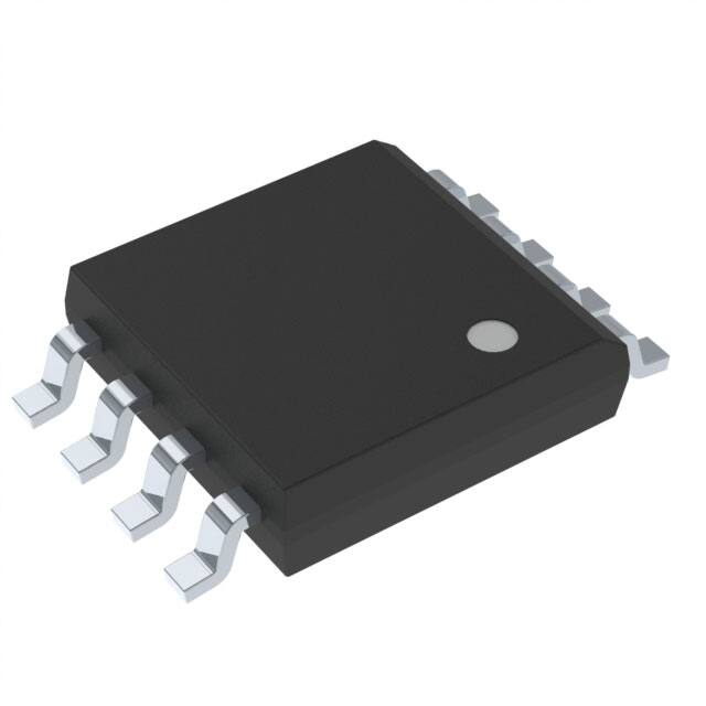
Industry Standard Green (Pb/Halide-free/RoHS Compliant) Package Options
– 8-lead SOIC (150-mil and 208-mil wide)
– 8-pad Ultra Thin DFN (5 x 6 x 0.6mm)
16-Megabit
2.3V or 2.7V
Minimum
SPI Serial Flash
Memory
AT25DF161
(Not Recommended
for New Designs)
3687H–DFLASH–5/2013
�1.
Description
The AT25DF161 is a serial interface Flash memory device designed for use in a wide variety of high-volume consumer
based applications in which program code is shadowed from Flash memory into embedded or external RAM for execution.
The flexible erase architecture of the AT25DF161, with its erase granularity as small as 4-Kbytes, makes it ideal for data
storage as well, eliminating the need for additional data storage EEPROM devices.
The physical sectoring and the erase block sizes of the AT25DF161 have been optimized to meet the needs of today's
code and data storage applications. By optimizing the size of the physical sectors and erase blocks, the memory space can
be used much more efficiently. Because certain code modules and data storage segments must reside by themselves in
their own protected sectors, the wasted and unused memory space that occurs with large sectored and large block erase
Flash memory devices can be greatly reduced. This increased memory space efficiency allows additional code routines and
data storage segments to be added while still maintaining the same overall device density.
The AT25DF161 also offers a sophisticated method for protecting individual sectors against erroneous or malicious
program and erase operations. By providing the ability to individually protect and unprotect sectors, a system can
unprotect a specific sector to modify its contents while keeping the remaining sectors of the memory array securely
protected. This is useful in applications where program code is patched or updated on a subroutine or module basis, or in
applications where data storage segments need to be modified without running the risk of errant modifications to the
program code segments. In addition to individual sector protection capabilities, the AT25DF161 incorporates Global Protect
and Global Unprotect features that allow the entire memory array to be either protected or unprotected all at once. This
reduces overhead during the manufacturing process since sectors do not have to be unprotected one-by-one prior to
initial programming.
To take code and data protection to the next level, the AT25DF161 incorporates a sector lockdown mechanism that allows
any combination of individual 64-Kbyte sectors to be locked down and become permanently read-only. This addresses the
need of certain secure applications that require portions of the Flash memory array to be permanently protected against
malicious attempts at altering program code, data modules, security information, or encryption/decryption algorithms, keys,
and routines. The device also contains a specialized OTP (One-Time Programmable) Security Register that can be used for
purposes such as unique device serialization, system-level Electronic Serial Number (ESN) storage, locked key storage,
etc.
Specifically designed for use in 3V systems, the AT25DF161 supports read, program, and erase operations with a supply
voltage range of 2.3V to 3.6V or 2.7V to 3.6V. No separate voltage is required for programming and erasing.
2
AT25DF161
3687H–DFLASH–5/2013
�AT25DF161
2.
Pin Descriptions and Pinouts
Table 2-1.
Pin Descriptions
Asserted
State
Type
CS
CHIP SELECT: Asserting the CS pin selects the device. When the CS pin is deasserted, the device
will be deselected and normally be placed in standby mode (not Deep Power-Down mode), and the
SO pin will be in a high-impedance state. When the device is deselected, data will not be accepted on
the SI pin.
A high-to-low transition on the CS pin is required to start an operation, and a low-to-high transition is
required to end an operation. When ending an internally self-timed operation such as a program or
erase cycle, the device will not enter the standby mode until the completion of the operation.
Low
Input
SCK
SERIAL CLOCK: This pin is used to provide a clock to the device and is used to control the flow of
data to and from the device. Command, address, and input data present on the SI pin is always latched
in on the rising edge of SCK, while output data on the SO pin is always clocked out on the falling edge
of SCK.
-
Input
SI (SIO)
SERIAL INPUT (SERIAL INPUT/OUTPUT): The SI pin is used to shift data into the device. The SI
pin is used for all data input including command and address sequences. Data on the SI pin is always
latched in on the rising edge of SCK.
With the Dual-Output Read Array command, the SI pin becomes an output pin (SIO) to allow two bits
of data (on the SO and SIO pins) to be clocked out on every falling edge of SCK. To maintain
consistency with SPI nomenclature, the SIO pin will be referenced as SI throughout the document
with exception to sections dealing with the Dual-Output Read Array command in which it will be
referenced as SIO.
Data present on the SI pin will be ignored whenever the device is deselected (CS is deasserted).
-
Input/Output
SO (SOI)
SERIAL OUTPUT (SERIAL OUTPUT/INPUT): The SO pin is used to shift data out from the device.
Data on the SO pin is always clocked out on the falling edge of SCK.
With the Dual-Input Byte/Page Program command, the SO pin becomes an input pin (SOI) to allow
two bits of data (on the SOI and SI pins) to be clocked in on every rising edge of SCK. To maintain
consistency with SPI nomenclature, the SOI pin will be referenced as SO throughout the document
with exception to sections dealing with the Dual-Input Byte/Page Program command in which it will
be referenced as SOI.
The SO pin will be in a high-impedance state whenever the device is deselected (CS is deasserted).
-
Output/Input
WP
WRITE PROTECT: The WP pin controls the hardware locking feature of the device. Please refer to
“Protection Commands and Features” on page 18 for more details on protection features and the WP
pin.
The WP pin is internally pulled-high and may be left floating if hardware controlled protection will not
be used. However, it is recommended that the WP pin also be externally connected to VCC whenever
possible.
Low
Input
HOLD
HOLD: The HOLD pin is used to temporarily pause serial communication without deselecting or
resetting the device. While the HOLD pin is asserted, transitions on the SCK pin and data on the SI pin
will be ignored, and the SO pin will be in a high-impedance state.
The CS pin must be asserted, and the SCK pin must be in the low state in order for a Hold condition to
start. A Hold condition pauses serial communication only and does not have an effect on internally selftimed operations such as a program or erase cycle. Please refer to “Hold” on page 39 for additional
details on the Hold operation.
The HOLD pin is internally pulled-high and may be left floating if the Hold function will not be used.
However, it is recommended that the HOLD pin also be externally connected to VCC whenever
possible.
Low
Input
VCC
DEVICE POWER SUPPLY: The VCC pin is used to supply the source voltage to the device.
Operations at invalid VCC voltages may produce spurious results and should not be attempted.
-
Power
GND
GROUND: The ground reference for the power supply. GND should be connected to the system
ground.
-
Power
Symbol
Name and Function
3
3687H–DFLASH–5/2013
�Figure 2-1.
Pin Configurations
8-UDFN
8-SOIC
CS
SO (SOI)
WP
GND
1
8 VCC
2
7 HOLD
3
6 SCK
4
5 SI (SIO)
CS
SO (SOI)
WP
GND
8 VCC
2
7 HOLD
3
6 SCK
4
5 SI (SIO)
Top View
Top View
3.
1
Block Diagram
Figure 3-1.
Block Diagram
CONTROL AND
PROTECTION LOGIC
CS
SRAM
DATA BUFFER
SCK
SO (SOI)
WP
HOLD
4.
INTERFACE
CONTROL
AND
LOGIC
Y-DECODER
ADDRESS LATCH
SI (SIO)
I/O BUFFERS
AND LATCHES
X-DECODER
Y-GATING
FLASH
MEMORY
ARRAY
Memory Array
To provide the greatest flexibility, the memory array of the AT25DF161 can be erased in four levels of granularity including
a full chip erase. In addition, the array has been divided into physical sectors of uniform size, of which each sector can be
individually protected from program and erase operations. The size of the physical sectors is optimized for both code and
data storage applications, allowing both code and data segments to reside in their own isolated regions. The Memory
Architecture Diagram illustrates the breakdown of each erase level as well as the breakdown of each physical sector.
4
AT25DF161
3687H–DFLASH–5/2013
�AT25DF161
Figure 4-1.
Memory Architecture Diagram
5
3687H–DFLASH–5/2013
�5.
Device Operation
The AT25DF161 is controlled by a set of instructions that are sent from a host controller, commonly referred to as the SPI
Master. The SPI Master communicates with the AT25DF161 via the SPI bus which is comprised of four signal lines: Chip
Select (CS), Serial Clock (SCK), Serial Input (SI), and Serial Output (SO).
The AT25DF161 features a dual-input program mode in which the SO pin becomes an input. Similarly, the device also
features a dual-output read mode in which the SI pin becomes an output. In the Dual-Input Byte/Page Program command
description, the SO pin will be referred to as the SOI (Serial Output/Input) pin, and in the Dual-Output Read Array
command, the SI pin will be referenced as the SIO (Serial Input/Output) pin.
The SPI protocol defines a total of four modes of operation (mode 0, 1, 2, or 3) with each mode differing in respect to the
SCK polarity and phase and how the polarity and phase control the flow of data on the SPI bus. The AT25DF161 supports
the two most common modes, SPI Modes 0 and 3. The only difference between SPI Modes 0 and 3 is the polarity of the
SCK signal when in the inactive state (when the SPI Master is in standby mode and not transferring any data). With SPI
Modes 0 and 3, data is always latched in on the rising edge of SCK and always output on the falling edge of SCK.
Figure 5-1.
SPI Mode 0 and 3
CS
SCK
SI
06%
SO
6.
/6%
06%
/6%
Commands and Addressing
A valid instruction or operation must always be started by first asserting the CS pin. After the CS pin has been asserted, the
host controller must then clock out a valid 8-bit opcode on the SPI bus. Following the opcode, instruction dependent
information such as address and data bytes would then be clocked out by the host controller. All opcode, address, and data
bytes are transferred with the most-significant bit (MSB) first. An operation is ended by deasserting the CS pin.
Opcodes not supported by the AT25DF161 will be ignored by the device and no operation will be started. The device will
continue to ignore any data presented on the SI pin until the start of the next operation (CS pin being deasserted and then
reasserted). In addition, if the CS pin is deasserted before complete opcode and address information is sent to the device,
then no operation will be performed and the device will simply return to the idle state and wait for the next operation.
Addressing of the device requires a total of three bytes of information to be sent, representing address bits A23-A0. Since
the upper address limit of the AT25DF161 memory array is 1FFFFFh, address bits A23-A21 are always ignored by the
device.
6
AT25DF161
3687H–DFLASH–5/2013
�AT25DF161
Table 6-1.
Command Listing
Command
Opcode
Clock
Frequency
Address
Bytes
Dummy
Bytes
Data
Bytes
Read Commands
1Bh
0001 1011
Up to 100MHz
3
2
1+
0Bh
0000 1011
Up to 85MHz
3
1
1+
03h
0000 0011
Up to 50MHz
3
0
1+
3Bh
0011 1011
Up to 85MHz
3
1
1+
Block Erase (4-KBytes)
20h
0010 0000
Up to 100MHz
3
0
0
Block Erase (32-KBytes)
52h
0101 0010
Up to 100MHz
3
0
0
Block Erase (64-KBytes)
D8h
1101 1000
Up to 100MHz
3
0
0
60h
0110 0000
Up to 100MHz
0
0
0
C7h
1100 0111
Up to 100MHz
0
0
0
Byte/Page Program (1- to 256-Bytes)
02h
0000 0010
Up to 100MHz
3
0
1+
Dual-Input Byte/Page Program
(1- to 256-Bytes)
A2h
1010 0010
Up to 100MHz
3
0
1+
Program/Erase Suspend
B0h
1011 0000
Up to 100MHz
0
0
0
Program/Erase Resume
D0h
1101 0000
Up to 100MHz
0
0
0
Write Enable
06h
0000 0110
Up to 100MHz
0
0
0
Write Disable
04h
0000 0100
Up to 100MHz
0
0
0
Protect Sector
36h
0011 0110
Up to 100MHz
3
0
0
Unprotect Sector
39h
0011 1001
Up to 100MHz
3
0
0
Read Array
Dual-Output Read Array
Program and Erase Commands
Chip Erase
Protection Commands
Global Protect/Unprotect
Read Sector Protection Registers
Use Write Status Register Byte 1 Command
3Ch
0011 1100
Up to 100MHz
3
0
1+
Sector Lockdown
33h
0011 0011
Up to 100MHz
3
0
1
Freeze Sector Lockdown State
34h
0011 0100
Up to 100MHz
3
0
1
Read Sector Lockdown Registers
35h
0011 0101
Up to 100MHz
3
0
1+
Program OTP Security Register
9Bh
1001 1011
Up to 100MHz
3
0
1+
Read OTP Security Register
77h
0111 0111
Up to 100MHz
3
2
1+
Read Status Register
05h
0000 0101
Up to 100MHz
0
0
1+
Write Status Register Byte 1
01h
0000 0001
Up to 100MHz
0
0
1
Write Status Register Byte 2
31h
0011 0001
Up to 100MHz
0
0
1
Reset
F0h
1111 0000
Up to 100MHz
0
0
1
Read Manufacturer and Device ID
9Fh
1001 1111
Up to 85MHz
0
0
1 to 4
Deep Power-Down
B9h
1011 1001
Up to 100MHz
0
0
0
Resume from Deep Power-Down
ABh
1010 1011
Up to 100MHz
0
0
0
Security Commands
Status Register Commands
Miscellaneous Commands
7
3687H–DFLASH–5/2013
�7.
Read Commands
7.1
Read Array
The Read Array command can be used to sequentially read a continuous stream of data from the device by simply
providing the clock signal once the initial starting address has been specified. The device incorporates an internal address
counter that automatically increments on every clock cycle.
Three opcodes (1Bh, 0Bh, and 03h) can be used for the Read Array command. The use of each opcode depends on the
maximum clock frequency that will be used to read data from the device. The 0Bh opcode can be used at any clock
frequency up to the maximum specified by fCLK, and the 03h opcode can be used for lower frequency read operations up
to the maximum specified by fRDLF. The 1Bh opcode allows the highest read performance possible and can be used at any
clock frequency up to the maximum specified by fMAX; however, use of the 1Bh opcode at clock frequencies above fCLK
should be reserved to systems employing RapidS™ protocol.
To perform the Read Array operation, the CS pin must first be asserted and the appropriate opcode (1Bh, 0Bh, or 03h)
must be clocked into the device. After the opcode has been clocked in, the three address bytes must be clocked in to
specify the starting address location of the first byte to read within the memory array. Following the three address bytes,
additional dummy bytes may need to be clocked into the device depending on which opcode is used for the Read Array
operation. If the 1Bh opcode is used, then two dummy bytes must be clocked into the device after the three address
bytes. If the 0Bh opcode is used, then a single dummy byte must be clocked in after the address bytes.
After the three address bytes (and the dummy bytes or byte if using opcodes 1Bh or 0Bh) have been clocked in,
additional clock cycles will result in data being output on the SO pin. The data is always output with the MSB of a byte first.
When the last byte (1FFFFFh) of the memory array has been read, the device will continue reading back at the beginning
of the array (000000h). No delays will be incurred when wrapping around from the end of the array to the beginning of
the array.
Deasserting the CS pin will terminate the read operation and put the SO pin into a high-impedance state. The CS pin can
be deasserted at any time and does not require that a full byte of data be read.
Figure 7-1.
Read Array – 1Bh Opcode
CS
�
�
�
�
�
�
�
�
�
�
�� �� ��
�� �� �� �� �� �� �� �� �� �� �� �� �� �� �� �� �� �� �� �� �� �� �� �� �� �� �� ��
SCK
23&2'(
SI
�
�
�
�
�
$''5(66�%,76�$���$�
�
06%
�
�
$
06%
$
$
$
$
$
$
'21
7�&$5(
$
$
;
06%
;
;
;
;
;
'21
7�&$5(
;
;
;
;
;
;
;
;
;
;
06%
'$7$�%


 工商网监
湘ICP备2023018690号
工商网监
湘ICP备2023018690号
