DATASHEET
IDT9170B
CLOCK SYNCHRONIZER AND MULTIPLIER
Description
Features
The IDT9170B generates an output clock which is
synchronized to a given continuous input clock with zero
delay (±1ns at 5 V VDD). Using IDT’s proprietary
phase-locked loop (PLL) analog CMOS technology, the
IDT9170B is useful for regenerating clocks in high speed
systems where skew is a major concern. By the use of the
two select pins, multiples or divisions of the input clock can
be generated with zero delay (see Tables 2 and 3). The
standard versions produce two outputs, where CLK2 is
always a divide by two version of CLK1.
• On-chip Phase-Locked Loop for clocks synchronization.
• Synchronizes frequencies up to 107 MHz
(output) @ 5.0 V
• ±1ns skew (max) between input & output clocks @ 5.0 V
• Can recover poor duty cycle clocks
• CLK1 to CLK2 skew controlled to within ±1ns @
5.0 V
•
•
•
•
•
The IDT9170B is also useful to recover poor duty cycle
clocks. A 50 MHz signal with a 20/80% duty cycle, for
example, can be regenerated to the 48/52% typical of the
part.
The IDT9170B allows the user to control the PLL feedback,
making it possible, with an additional 74F240 octal buffer
(or other such device that offers controlled skew outputs), to
synchronize up to 8 output clocks with zero delay compared
to the input (see Figure 1). Application notes for the
IDT9170B are available. Please consult IDT.
3.0 - 5.5 V supply range
Low power CMOS technology
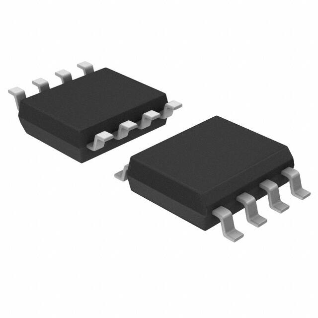
Small 8-pin DIP or SOIC package
On chip loop filter
IDT9170B-01 for output clocks 20-107 MHz @ 5.0 V,
20 - 66.7 MHz @ 3.3 V
• IDT9170B-02 for output clocks 5-26.75 MHz @ 5.0 V,
5 - 16.7 MHz @ 3.3 V
Block Diagram
IDT™ CLOCK SYNCHRONIZER AND MULTIPLIER
1
IDT9170B
REV B 052609
�IDT9170B
CLOCK SYNCHRONIZER AND MULTIPLIER
CLOCK SYNTHESIZER
Pin Assignment
FBI N
1
8
CLK2
IN
2
7
VDD
GND
3
6
CLK1
FS0
4
5
FS1
Pin Descriptions
Pin
Number
Pin
Name
Pin
Type
1
FBIN
Input
Pin Description
Feedback input.
2
IN
Input
Input for reference clock.
3
GND
Power
Connect to ground.
4
FS0
Input
Frequency select 0.
5
FS1
Input
Frequency select 1.
6
CLK1
Output
Clock output 1. See tables 1, 2 for values.
7
VDD
Power
Power supply.
8
CLK2
Output
Clock output 2. See tables 1, 2 for values.
Using the IDT9170B
4. The CLK1 frequency ranges are:
The IDT9170B has the following characteristics:
1. Rising edges at IN and FBIN are lined up. Falling edges
are not synchronized.
2. The relationship between the frequencies at FBIN and IN
with CLK1 feedback is shown in Table 1 below.
0
2 * fIN
0
1
4 * fIN
1
0
fIN
1
1
8 * fIN
很抱歉,暂时无法提供与“ICS9170B-02CS08LFT”相匹配的价格&库存,您可以联系我们找货
免费人工找货