IDT3CP0C02-18.432NSGE 数据手册
CMOS Oscillator
3C02
PRELIMINARY DATA SHEET
General Description
Features
Using the IDT CMOS oscillator technology, originally developed by
Mobius Microsytems, the 3C02 replaces quartz crystal based
resonators and oscillators with a monolithic CMOS IC at the thinnest
possible form factors without the use of any mechanical frequency
source or PLL. The product is specially designed to work with the
next generation USB 3.0 Super Speed, PCIe® Gen1/2 and S-ATA
interface controller ICs and systems.
•
•
•
•
All-CMOS Temperature Compensated Oscillator
Excellent Frequency Accuracy: +/- 100ppm total
Ultra-low power operation (2mA typical at 1.8V supply)
No quartz or PLL used: very low jitter performance leading to low
link Bit Error Rates (BER)
• Excellent reliability: Shock and vibration resistant
• Many frequencies are supported
• Factory programmable from 6 to 133MHz
Ordering Information
Pin Assignment
3C P 0
C 02 - FFF NSG X 8
1
4
2
3
5
6
7
8 9
1) IDT Base Part Number for 100ppm CMOS Oscillator
2) Supply Voltage Configuration
•
P: 1.8V to 3.3V continuous operation
3) Output Signal Type
•
0: LVCMOS Output
4) “C” indicates integrated CMOS Oscillator
5) “XX” is product specific code that indicated product sequence
6) FFF: Factory Programmed Frequency in MHz
7) Package Options*
•
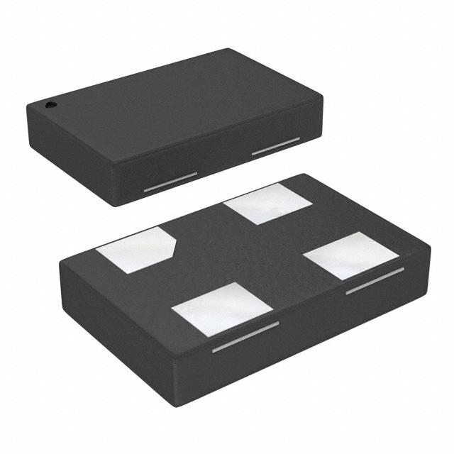
NSG: 5x3.2, 4-Pin Package
•
NVG: 2.5x2.0, 4-Pin Package2
•
M: SOIC, 8-pin Package2
Table 1. Pin Descriptions
8) Temperature Grade
•
“E” -20 to 70oC Extended Commercial Temperature Range
•
“ “ 0 to 70oC Commercial Temperature Range,ie. default is blank2
•
“R” -20 to 85oC Restricted Industrial Temperature Range
9) Tape & Reel Option
•
“ “: Shipped in Tube i.e. default is blank
•
8: Shipped in Tape & Reel
No
Name
Type
Description
1
CE
Input
Pullup
Chip Enable. Internal Pullup. 3C02 is
enabled when HIGH. When LOW, OUT has
a weak pull-down to GND internally
2
VSS
Power
System Ground
3
OUT
Output
Frequency Output
4
VDD
Power
Power Supply. Use a 0.1µF decoupling
capacitor between VDD and VSS
2
1
:This product is rated “Green”, please contact factory for environmental compliancy
information
2
: Future product. Not available for design-in. Please contact your IDT representative for
details
The Preliminary Information presented herein represents a product in pre-production. The noted characteristics are based on initial product characterization and/or qualification.
Integrated Device Technology, Incorporated (IDT) reserves the right to change any circuitry or specifications without notice
3C02 REVISION B DATE, 10/20/2010
1
©2010 Integrated Device Technology, Inc.
�3C02 Preliminary Data Sheet
CMOS OSCILLATOR
Table 2. Pin Descriptions
Below Pin Descriptions apply to SOIC-8 Package
No
Name
Type
Description
1
CE
Input
Pullup
Chip Enable. Internal Pullup. 3C02 is
enabled when HIGH.When LOW, OUT has
a weak pull-down to GND internally
4
VSS
Power
System Ground
6
OUT
Output
Frequency Output
8
VDD
Power
Power Supply. Use a 0.1µF decoupling
capacitor between VDD and VSS
2,3,5,7
NC
No Connect Pins. These pins may be left
floating.
Block Diagram
Functional Description
3C02 is a monolithic all-CMOS frequency source. The internal CMOS Oscillator generates the factory-programmed frequencies with high
accuracy and excellent phase noise and jitter. The device is a silicon alternative to quartz based crystal resonators and oscillators. Various
programming and configuration options are supported as given in the Part Ordering Information section above. The easy-to-use device offers
programmable frequencies and various supply voltage configurations. Offered in common crystal oscillator pin-outs, the 3C02 allows the
designer to disable the oscillator via the CE pin to enter a very low current, quiescent state. The CMOS oscillator features very fast start-up
time to enable rapid wake-up from the quiescent state. All required circuit elements other than those that are noted in the Pin Descriptions
Table (Table.1) above are internal to the device.
3C02 REVISION B DATE, 10/20/2010
2
©2010 Integrated Device Technology, Inc.
�3C02 Preliminary Data Sheet
CMOS OSCILLATOR
Absolute Maximum Ratings
NOTE: Stresses beyond those listed under Absolute Maximum Ratings may cause permanent damage to the device. These ratings are stress
specifications only. Functional operation of product at these conditions or any conditions beyond those listed in the DC Characteristics or AC
Characteristics is not implied. Exposure to absolute maximum rating conditions for extended periods may affect product reliability.
Item
Rating
Supply Voltage, VDD
4.6V
Input, VI (CE pin)
-0.5V to VDD + 0.5V
Output, VO (OUT pin)
-0.5V to VDD + 0.5V
Storage Temperature
-65oC to 150oC
Electrical Characteristics5 [3.3V]
VDD=3.0V to 3.6V, TA=-20 to 70oC unless otherwise noted. Typical values are measured at VDD=3.3V, TA=35oC
Parameter
Symbol
Conditions
ESD
Human Body Model, tested per JESD D22-A114
ElectroStaticDischa
rge
Supply Voltage
Input LOW level
Input HIGH level
Supply Current
Quiescent Current
Output LOW level
Output HIGH level
Output Frequency
VDD
VIL
VIH
IDD
IDDQ
VOL
VOH
FOUT
Frequency Stability
FTOT
Rise Time
Fall Time
RT
FT
Duty Cycle
DC
Power-up time
ton
Period Jitter
PJRMS
Cycle-cycle Jitter
CJ
Phase Noise
PN
Min
3
Normal Operation
CE pin
CE pin
Active supply current, VDD=3.3V, T=35oC, no output load
CE=LOW, output disabled
IOL = -4mA
IOH = 4mA
Factory Programmable.Contact IDT for frequencies not listed
Total Frequency Stability over temperature,supply
variation,aging (1st year at 35oC),shock&vibration. “E” device
option, over -20 to 70oC range
20% to 80% x VDD. Output load (CL) =8pF, NSG-option
80% to 20% x VDD. Output load (CL) =8pF, NSG-option
Clock output duty cycle. Measured under 80MHz, VDD/2,
CL=8pF
Clock output duty cycle. Measured over 80MHz, VDD/2,
CL=8pF
Output valid time after VDD meets the specified range&CE
transition
Total RMS Period Jitter (including random and
deterministic)1,2
The absolute value of max change in the periods of any 2
adjacent cycles1,2,4
1MHz offset from carrier1,2
Typ
Max
4000
3.0
-0.3
VDD*0.7
Units
V
3.3
3.6
VDD*0.3
VDD+0.3
3.0
1
0.5
V
V
V
mA
µA
V
V
MHz
+100
ppm
1.9
1.9
ns
ns
45
55
%
40
60
%
400
µs
2.5
0.2
VDD-0.5
12,48,75,125
50
100
3.5
-140
psRMS
50
ps
-135
dBc/Hz
Notes 1. Measured with a 50Ω to GND termination
2: Measured at 48MHz output frequency
3. The 3C02 will support continuous VDD operation from 1.62 to 3.6V. The device can be powered up with a supply voltage at any of the 3 main supply rails of 1.8V, 2.5V or 3.3V.
4. Measured over 1000 cycles per JEDEC standard 65
5. Electrical parameters are guaranteed by design and characterization over the specified ambient operating temperature range, which is established when the device is mounted in a
test socket with maintained transverse airflow greater than 500lfpm. The device will meet specifications after thermal equilibrium has been reached under these conditions.
3C02 REVISION B DATE, 10/20/2010
3
©2010 Integrated Device Technology, Inc.
�3C02 Preliminary Data Sheet
CMOS OSCILLATOR
5
Electrical Characteristics [2.5V]
VDD=2.25V to 2.75V, TA=-20 to 70oC unless otherwise noted. Typical values are measured at VDD=2.5V, TA=35oC
Parameter
Symbol
Conditions
Min
ESD
Human Body Model, tested per JESD D22-A114
4000
VDD
VIL
VIH
IDD
IDDQ
VOL
VOH
FOUT
Normal Operation3
CE pin
CE pin
Active supply current, VDD=2.5V, T=35oC, no output load
CE=LOW, output disabled
IOL = -3mA
IOH = 3mA
Factory Programmable.Contact IDT for frequencies not listed
Total Frequency Stability over temperature,supply
variation,aging (1st year at 35oC),shock&vibration. “E” device
option, over -20 to 70oC range
20% to 80% x VDD. Output load (CL) =7pF, NSG-option
80% to 20% x VDD. Output load (CL) =7pF, NSG-option
Clock output duty cycle. Measured under 100MHz at VDD/2,
CL=7pF
Clock output duty cycle. Measured over 100MHz at VDD/2,
CL=7pF
Output valid time after VDD meets the specified range&CE
transition
Total RMS Period Jitter (including random and
deterministic)1,2
The absolute value of max change in the periods of any 2
adjacent cycles1,2,4
1MHz offset from carrier1,2
2.25
-0.3
VDD*0.7
ElectroStaticDischa
rge
Supply Voltage
Input LOW level
Input HIGH level
Supply Current
Quiescent Current
Output LOW level
Output HIGH level
Output Frequency
Frequency Stability
FTOT
Rise Time
Fall Time
RT
FT
Duty Cycle
DC
Power-up time
ton
Period Jitter
PJRMS
Cycle-cycle Jitter
CJ
Phase Noise
PN
Typ
Max
Units
V
2.5
2.75
VDD*0.3
VDD+0.3
2.75
1
0.4
V
V
V
mA
µA
V
V
MHz
+100
ppm
2.3
2.3
ns
ns
45
55
%
40
60
%
400
µs
2.25
0.2
VDD-0.4
12,48,75,125
50
100
3.5
-140
psRMS
50
ps
-135
dBc/Hz
Notes 1. Measured with a 50Ω to GND termination
2: Measured at 48MHz output frequency
3. The 3C02 will support continuous VDD operation from 1.62 to 3.6V. The device can be powered up with a supply voltage at any of the 3 main supply rails of 1.8V, 2.5V or 3.3V.
4. Measured over 1000 cycles per JEDEC standard 65
5. Electrical parameters are guaranteed by design and characterization over the specified ambient operating temperature range, which is established when the device is mounted in a
test socket with maintained transverse airflow greater than 500lfpm. The device will meet specifications after thermal equilibrium has been reached under these conditions.
3C02 REVISION B DATE, 10/20/2010
4
©2010 Integrated Device Technology, Inc.
�3C02 Preliminary Data Sheet
CMOS OSCILLATOR
5
Electrical Characteristics [1.8V]
VDD=1.62V to 1.98V, TA=-20 to 70oC unless otherwise noted. Typical values are measured at VDD=1.8V, TA=35oC
Parameter
Symbol
Conditions
Min
ESD
Human Body Model, tested per JESD D22-A114
4000
VDD
VIL
V IH
IDD
IDDQ
VOL
VOH
FOUT
Normal Operation3
CE pin
CE pin
Active supply current, VDD=1.8V, T=35oC, no output load
CE=LOW, output disabled
IOL = -1.8mA
IOH = 1.8mA
Factory Programmable.Contact IDT for frequencies not listed
Total Frequency Stability over temperature,supply
variation,aging (1st year at 35oC),shock&vibration. “E” device
option, over -20 to 70oC range
20% to 80% x VDD. Output load (CL) =4pF, NSG-option
80% to 20% x VDD. Output load (CL) =4pF, NSG-option
Clock output duty cycle. Measured at VDD/2, CL=4pF
Output valid time after VDD meets the specified range&CE
transition
Total RMS Period Jitter (including random and
deterministic)1,2
The absolute value of max change in the periods of any 2
adjacent cycles1,2,4
1MHz offset from carrier1,2
1.62
-0.3
VDD*0.7
ElectroStaticDischa
rge
Supply Voltage
Input LOW level
Input HIGH level
Supply Current
Quiescent Current
Output LOW level
Output HIGH level
Output Frequency
Frequency Stability
FTOT
Rise Time
Fall Time
Duty Cycle
RT
FT
DC
Power-up time
ton
Period Jitter
PJRMS
Cycle-cycle Jitter
CJ
Phase Noise
PN
Typ
Max
V
1.8
2.0
0.2
1.98
VDD*0.3
VDD+0.3
2.5
1
0.3
V
V
V
mA
µA
V
V
MHz
+100
ppm
2.75
2.75
55
ns
ns
%
400
µs
VDD-0.3
12,48,75,125
45
50
Units
100
3.5
-140
psRMS
50
ps
-135
dBc/Hz
Notes 1. Measured with a 50Ω to GND termination
2: Measured at 48MHz output frequency
3. The 3C02 will support continuous VDD operation from 1.62 to 3.6V. The device can be powered up with a supply voltage at any of the 3 main supply rails of 1.8V, 2.5V or 3.3V.
4. Measured over 1000 cycles per JEDEC standard 65
5. Electrical parameters are guaranteed by design and characterization over the specified ambient operating temperature range, which is established when the device is mounted in a
test socket with maintained transverse airflow greater than 500lfpm. The device will meet specifications after thermal equilibrium has been reached under these conditions.
Application Diagram
Below is a representative application diagram to evaluate the 3C02. For 50Ohm terminated measurements, a balun is necessary to provide
proper impedance matching
3C02 REVISION B DATE, 10/20/2010
5
©2010 Integrated Device Technology, Inc.
�3C02 Preliminary Data Sheet
CMOS OSCILLATOR
Package Outline and Package Dimensions
Package Outline for NSG -5.0x3.2x0.9mm, 4-pin package:
Below is the recommended PCB land pattern for the 3C02 NSG package:
3C02 REVISION B DATE, 10/20/2010
6
©2010 Integrated Device Technology, Inc.
�3C02 Preliminary Data Sheet
CMOS OSCILLATOR
Package Outline and Package Dimensions
Package Outline for NVG -2.5x2.0x0.55mm, 4-pin package:
Package Outline for SOIC, 8-pin package:
3C02 REVISION B DATE, 10/20/2010
7
©2010 Integrated Device Technology, Inc.
�3C02 Preliminary Data Sheet
6024 Silver Creek Valley Road
San Jose, California 95138
CMOS OSCILLATOR
Sales
800-345-7015 (inside USA)
+408-284-8200 (outside USA)
Fax: 408-284-2775
www.IDT.com
Technical Support
mobius@idt.com
+408-739-5400
DISCLAIMER Integrated Device Technology, Inc. (IDT) and its subsidiaries reserve the right to modify the products and/or specifications described herein at any time and at IDT’s sole discretion. All information in this document,
including descriptions of product features and performance, is subject to change without notice. Performance specifications and the operating parameters of the described products are determined in the independent state and are not
guaranteed to perform the same way when installed in customer products. The information contained herein is provided without representation or warranty of any kind, whether express or implied, including, but not limited to, the
suitability of IDT’s products for any particular purpose, an implied warranty of merchantability, or non-infringement of the intellectual property rights of others. This document is presented only as a guide and does not convey any
license under intellectual property rights of IDT or any third parties.
IDT’s products are not intended for use in life support systems or similar devices where the failure or malfunction of an IDT product can be reasonably expected to significantly affect the health or safety of users. Anyone using an IDT
product in such a manner does so at their own risk, absent an express, written agreement by IDT.
Integrated Device Technology, IDT and the IDT logo are registered trademarks of IDT. Other trademarks and service marks used herein, including protected names, logos and designs, are the property of IDT or their respective third
party owners.
Copyright 2010. All rights reserved.
�