SIGNS
DED FOR NEW DE
NOT RECOMMEN
T
EN
D REPLACEM
NO RECOMMENDE
er
nt at
nical Support Ce
/tsc
contact our Tech
co
www.intersil. m
1-888-INTERSIL or
DATASHEET
ISL54230
Octal Multiprotocol Switch
The Intersil ISL54230 is a multiprotocol Quad Double-Pole
Double-Throw (DPDT) analog switch that can operate from a
single +2.0V to +5.5V supply. It contains eight SPDT (Single
Pole/Double Throw) switches configured into four DPDT
blocks. Each DPDT block is independently controlled by a
logic input for Normally Open (NO) or Normally Closed (NC)
switch configuration.The part is designed for switching or
routing a combination of USB High-Speed, USB Full-Speed,
digital, and analog signals in portable battery powered
products.
Features
The digital inputs are 1.8V logic compatible when operated
with a 2.7V to 3.6V supply. The ISL54230 has two switch
enable pins to disable certain blocks of the switch. The
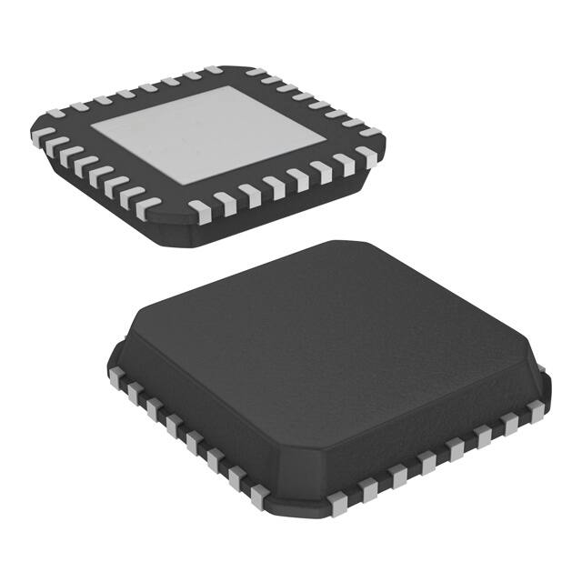
ISL54230 is available in a 36 ball 2.5mmx2.5mm WLCSP or a
32 Ld TQFN 5mmx5mm package. It operates over a
temperature range of -40 to +85°C.
• Two DPDT 1/6Switches
FN6825
Rev 2.00
May 28, 2009
• High Speed (480Mbps) and Full Speed (12Mbps)
Signaling Capability per USB 2.0
• Compliant with USB 2.0 Short Circuit and Overvoltage
Requirements Without Additional External Components
• 1.8V Logic Compatible (+2.7V to +3.6V Supply)
• Switch Terminals Overvoltage Protected Up to +5.5V
• Enable Pin to disable Switch Blocks
• Two DPDT USB 2.0 FS/HS Capable Switches
• USB Switch Low ON Capacitance . . . . . . . . . . . . . . . 12pF
• USB Switch Low ON-Resistance . . . . . . . . . . . . . . . . . 6
• Single Supply Operation (VDD) . . . . . . . . . +2.0V to +5.5V
Applications
• Low Power Consumption (PD) . . . . . . . . . . . . . . . . . .1µA
• Cellular/Mobile Phones
• Low I+ Current when VINH is not at the V+ Rail
• PDAs
• Digital Cameras and Camcorders
• Available in 36 Ball WLCSP and 32 Ld 5mmx5mm TQFN
Package
• USB/UART/Audio Switching
• Pb-Free (RoHS Compliant)
Ordering Information
Block Diagram
VDD
COM1A
IN1
COM1B
1
NO1A
NC1A
6
NO1B
NC1B
COM2A
HS_USB
NC2A
IN2
COM2B
NO2A
HS_USB
NO2B
NC2B
COM3A
HS_USB
NC3A
IN3
COM3B
HS_USB
COM4A
1
FN6825 Rev 2.00
May 28, 2009
NO3B
NC3B
NO4A
NC4A
IN4
COM4B
OE1
OE2
NO3A
6
NO4B
NC4B
GND
PART
PART NUMBER MARKING
ISL54230IRTZ
(Note 1)
TEMP.
RANGE
(°C)
PACKAGE
(Pb-Free)
PKG.
DWG. #
54230 IRTZ -40 to +85 32 Ld 5x5 TQFN
L32.5x5A
ISL54230IRTZ-T* 54230 IRTZ -40 to +85 32 Ld 5x5 TQFN
(Note 1)
L32.5x5A
ISL54230IIZ-T*
(Note 2)
W6x6.36
230Z
-40 to +85 36 Ball 6x6 Array
WLCSP
*Please refer to TB347 for details on reel specifications.
NOTES:
1. These Intersil Pb-free plastic packaged products employ special Pbfree material sets, molding compounds/die attach materials, and
100% matte tin plate plus anneal (e3 termination finish, which is
RoHS compliant and compatible with both SnPb and Pb-free
soldering operations). Intersil Pb-free products are MSL classified
at Pb-free peak reflow temperatures that meet or exceed the Pbfree requirements of IPC/JEDEC J STD-020.
2. These Intersil Pb-free WLCSP and BGA packaged products
products employ special Pb-free material sets; molding
compounds/die attach materials and SnAgCu - e1 solder ball
terminals, which are RoHS compliant and compatible with both
SnPb and Pb-free soldering operations. Intersil Pb-free WLCSP
and BGA packaged products are MSL classified at Pb-free peak
reflow temperatures that meet or exceed the Pb-free requirements
of IPC/JEDEC J STD-020.
Page 1 of 18
�ISL54230
Pinouts
ISL54230
(36 BALL 6X6 ARRAY WLCSP)
TOP VIEW
*Columns A, B, C = Left Plane
*Columns D, E, F = Right Plane
*Refer to OE Control
Truth Table, pg. 3
A
B
C
D
E
F
1
COM
2A
COM
2B
COM
1B
COM
4B
COM
3B
COM
3A
2
COM
1A
NC
1A
OE1
OE2
NC
4A
COM
4A
3
NO
1A
NC
2A
N.C.
N.C.
NC
3A
NO
4A
4
NO
2A
NC
2B
N.C.
N.C.
NC
3B
NO
3A
5
NO
2B
NC
1B
VDD
GND
NC
4B
NO
3B
6
NO
1B
IN1
IN2
IN3
IN4
NO
4B
HS USB
Switches 2A and 3A
HS USB
Switches 2B and 3B
6
Switches 1B and 4B
1
Switches 1A and 4A
FN6825 Rev 2.00
May 28, 2009
COM_3A
COM_3B
OE2
COM_4B
COM_1B
OE1
COM_2B
COM_2A
ISL54230
(32 LD 5X5 TQFN)
TOP VIEW
32
31
30
29
28
27
26
25
NC_4A
1
24
NC_1A
COM_4A
2
23
COM_1A
NC_3A
3
22
NC_2A
NO_4A
4
21
NO_1A
NO_3A
5
20
NO_2A
NC_3B
6
19
NC_2B
NO_3B
7
18
NO_2B
NC_4B
8
17
NC_1B
9
10
11
12
13
14
15
16
IN4
GND
IN3
IN2
VDD
IN1
NO_1B
*RIGHT PLANE
NO_4B
*LEFT PLANE
Page 2 of 18
�ISL54230
Pinouts
SWITCHES 1 AND 2
SWITCHES 3 AND 4
VDD
1 SWITCH
COM1A
COM2B
NO1B
6 SWITCH
NC3B
NO2B
USB HS SWITCH
NO4A
1 SWITCH
COM4A
NC2A
NO3B
USB HS SWITCH
NO2A
USB HS SWITCH
IN1
IN2
OE1
OE2
NC3A
COM3B
NC1B
NO3A
USB HS SWITCH
COM3A
NC1A
COM1B
COM2A
VDD
NO1A
NC4A
COM4B
6 SWITCH
IN3
IN4
OE1
OE2
LOGIC
CONTROL
NO4B
NC4B
NC2B
LOGIC
CONTROL
GND
GND
NOTE: Switches shown in Logic “0” position. Logic “0” when INx
8kV
Machine Model . . . . . . . . . . . . . . . . . . . . . . . . . . . . . . . . . .>400V
Charged Device Model. . . . . . . . . . . . . . . . . . . . . . . . . . . . . .>2kV
Thermal Resistance (Typical, Notes 4, 5)
JA (°C/W)
JC (°C/W)
32 Ld 5x5mm TQFN Package . . . . . . .
30
1.5
36 Ball WLCSP Package . . . . . . . . . . .
60
Maximum Junction Temperature (Plastic Package). . . . . . . +150°C
Maximum Storage Temperature Range . . . . . . . . . . . -65°C to +150°C
Operating Conditions
Temperature Range . . . . . . . . . . . . . . . . . . . . . . . . . -40°C to +85°C
Logic Control Input Voltage . . . . . . . . . . . . . . . . . . . . . . . 0V to VDD
Analog Signal Range . . . . . . . . . . . . . . . . . . . . . . . . . . . . 0V to VDD
CAUTION: Do not operate at or near the maximum ratings listed for extended periods of time. Exposure to such conditions may adversely impact product reliability and
result in failures not covered by warranty.
NOTES:
3. Signals on NCx, NOx, COMx, INx, and OEx exceeding VDD or GND by specified amount are clamped. Limit current to maximum current ratings.
4. JA is measured in free air with the component mounted on a high effective thermal conductivity test board with “direct attach” features. See
Tech Brief TB379 for details.
5. For JC, the “case temperature” location is the center of the exposed metal pad on the package underside.
Electrical Specifications - 2.7V to 3.6V Supply
PARAMETER
Test Conditions: VDD = +2.7V, GND = 0V, VINxH = 1.4V, VINxL = 0.5V,
VOExH = 1.4V, VOExL = 0.5V, (Note 6), Unless Otherwise Specified.
TEST CONDITIONS
TEMP
MIN
MAX
(°C) (Notes 7, 8) TYP (Notes 7, 8) UNITS
ANALOG SWITCH CHARACTERISTICS
USB HS Switch, COM2x and COM3x
Analog Signal Range, VANALOG
Full
0
-
VDD
V
ON-Resistance, rON
High Speed
VDD = 2.7V, VOEx = VOExH, ICOMx = 40mA, VNOx or
VNCx = 0V to 400mV (see Figure 1)
25
-
8.3
-
Full
-
9.25
-
rON Matching Between Channels,
rON, High Speed
VDD = 2.7V, VOEx = VOExH, ICOMx = 40mA, VNOx or
VNCx = Voltage at max rON, (Note 10)
25
-
0.11
-
Full
-
0.22
-
rON Flatness, rFLAT(ON)
High Speed
VDD = 2.7V, VOEx = VOExH, ICOMx = 40mA, VNOx or
VNCx = 0V to 400mV, (Note 9)
25
-
1.45
-
Full
-
1.8
-
ON-Resistance, rON
Full Speed
VDD = 2.7V, VOEx = VOExH, ICOMx = 1mA, VNOx or
VNCx =0V to 2.7V (see Figure 1, Note 11)
25
-
130
150
Full
-
150
178
rON Matching Between Channels,
rON, Full-Speed
VDD = 2.7V, VOEx = VOExH, ICOMx = 1mA, VNOx or
VNCx = Voltage at max rON over signal range of 0V to 2.7V
(Note 10)
25
-
1.2
-
Full
-
2.6
-
rON Flatness, rFLAT(ON)
Full-Speed
VDD = 2.7V, VOEx = VOExH, ICOMx = 1mA, VNOx or
VNCx = 0V to 1V (Note 9)
25
-
4
-
ON-Resistance, rON
VDD = 2.7V, VOEx = VOExH, ICOMx = 1mA, VNOx or
VNCx = 0V to 1.8V (see Figure 1)
OFF Leakage Current, INOx(OFF) or VDD = 3.6V, VOEx = Such that switch is disabled,
INCx(OFF)
VCOMx = 0.3V, 3.3V, VNOx = 3.3V, 0.3V, VNCx = 3.3V, 0.3V
ON Leakage Current, ICOMx(ON)
FN6825 Rev 2.00
May 28, 2009
VDD = 3.6V, VOEx = VOExH, VCOMx = 0.3V, 3.3V,
VNOx = 0.3V, 3.3V, VNCx = 0.3V, 3.3V
Full
-
5
-
25
-
128
-
Full
-
140
-
25
-20
4
20
nA
Full
-100
-
100
nA
25
-50
4
50
nA
Full
-100
-
100
nA
Page 5 of 18
�ISL54230
Electrical Specifications - 2.7V to 3.6V Supply
PARAMETER
Test Conditions: VDD = +2.7V, GND = 0V, VINxH = 1.4V, VINxL = 0.5V,
VOExH = 1.4V, VOExL = 0.5V, (Note 6), Unless Otherwise Specified. (Continued)
TEST CONDITIONS
Power OFF Leakage Current, ID+, ID- VDD = 0V, VNOx = 0V to 5.25V, VNCx= 0V to 5.25V,
VINX = 0V, VOEX such that switch is disabled
(see Figure 5)
TEMP
MIN
MAX
(°C) (Notes 7, 8) TYP (Notes 7, 8) UNITS
25
-
2
100
nA
Full
-
-
2
µA
Full
0
-
VDD
V
25
-
1.26
1.5
Full
-
1.5
1.74
1Switch, COM1A and COM4A
Analog Signal Range, VANALOG
ON-Resistance, rON
VDD = 2.7V, VOEx = VOExH, ICOMx = 100mA, VNOx or
VNCx = 0V to 2.7V (see Figure 1, Note 11)
rON Matching Between Channels,
rON
VDD = 2.7V, VOEx = VOExH, ICOMx = 100mA, VNOx or
VNCx = Voltage at max rON over signal range of 0V to 2.7V,
(Note 10)
rON Flatness, rFLAT(ON)
VDD = 2.7V, VOEx = VOExH, ICOMx = 100mA, VNOx or
VNCx = 0V to 2.7V (Note 9)
ON-Resistance, rON
VDD = 2.7V, VOEx = VOExH, ICOMx = 100mA, VNOx or
VNCx = 0V to 1.8V (see Figure 1)
OFF Leakage Current, INOx(OFF) or VDD = 3.6V, VOEx = VOExL, VCOMx = 0.3V, 3.3V,
INCx(OFF)
VNOx = 3.3V, 0.3V, VNCx = 3.3V, 0.3V
ON Leakage Current, ICOMx(ON)
VDD = 3.6V, VOEx = VOExH, VCOMx = 0.3V, 3.3V,
VNOx = 0.3V, 3.3V, VNCx = 0.3V, 3.3V
25
-
0.05
-
Full
-
0.07
-
25
-
0.37
0.52
Full
-
0.37
0.6
25
-
1.3
-
Full
-
1.4
-
25
-20
4
20
nA
Full
-150
-
150
nA
25
-50
10
50
nA
Full
-300
-
300
nA
Full
0
-
VDD
V
25
-
8
9.2
6 Switch, COM1B and COM4B
Analog Signal Range, VANALOG
ON-Resistance, rON
VDD = 2.7V, VOEx = VOExH, ICOMx = 40mA, VNOx or
VNCx = 0V to 2.7V (see Figure 1, Note 11)
rON Matching Between Channels,
rON
VDD = 2.7V, VOEx = VOExH, ICOMx = 40mA, VNOx or
VNC x= Voltage at max rON over signal range of 0V to 2.7V,
(Note 10)
rON Flatness, rFLAT(ON)
VDD = 2.7V, VOEx = VOExH, ICOMx = 40mA, VNOx or
VNCx = 0V to 2.7V (Note 9)
VDD = 2.7V, VOEx = VOExH, ICOMx = 40mA, VNOx or
VNCx = 0V to 1.8V (see Figure 1)
ON-Resistance, rON
Full
-
9.2
10.8
25
-
0.08
-
Full
-
0.3
-
25
-
1.9
2.8
Full
-
1.9
3.3
25
-
8
-
Full
-
8.8
-
OFF Leakage Current, INOx(OFF) or VDD = 3.6V, VOEx = VOExL, VCOMx = 0.3V, 3.3V,
INCx(OFF)
VNOx = 3.3V, 0.3V, VNCx = 3.3V, 0.3V
25
-20
4
20
nA
Full
-100
-
100
nA
VDD = 3.6V, VOEx = VOExH, VCOMx = 0.3V, 3.3V,
VNOx = 0.3V, 3.3V, VNCx = 0.3V, 3.3V
25
-50
4
50
nA
Full
-130
-
130
nA
ON Leakage Current, ICOMx(ON)
DYNAMIC CHARACTERISTICS
USB HS Switch
Skew, tSKEW
VDD = 3.0V, VOEx = VOExH, RL = 45,CL = 10pF,
tR = tF = 720ps at 480Mbps, Duty Cycle = 50%
(see Figure 6)
25
-
50
-
ps
Total Jitter, tJ
VDD =3.0V, VOEx = VOExH, RL = 45,CL = 10pF,
tR = tF = 750ps at 480Mbps
25
-
210
-
ps
Propagation Delay, tPD
VDD = 3.0V, VOEx = VOExH, RL = 45,CL = 10pF
see Figure 6)
25
-
250
-
ps
OFF-Isolation
VDD = 3.0V, RL = 50, f = 240MHz (see Figure 2)
25
-
-15
-
dB
FN6825 Rev 2.00
May 28, 2009
Page 6 of 18
�ISL54230
Electrical Specifications - 2.7V to 3.6V Supply
PARAMETER
Test Conditions: VDD = +2.7V, GND = 0V, VINxH = 1.4V, VINxL = 0.5V,
VOExH = 1.4V, VOExL = 0.5V, (Note 6), Unless Otherwise Specified. (Continued)
TEST CONDITIONS
TEMP
MIN
MAX
(°C) (Notes 7, 8) TYP (Notes 7, 8) UNITS
HS Switch -3dB Bandwidth,
Signal = 50mVRMS, RL = 50
25
-
500
-
MHz
OFF Capacitance, CNOxOFF or
CNCxOFF
f = 1MHz, VDD = 3.0V, VOEx = VOExH, VNOx or VNCx = 0V
(see Figure 3)
25
-
6.2
-
pF
COM ON Capacitance, CCOMxON
f = 1MHz, VDD = 3.0V, VOEx = VOExH, VNOx or VNCx = 0V
(see Figure 3)
25
-
12.5
-
pF
Crosstalk
VDD = 3.0V, RL = 50, f = 10MHz (see Figure 4)
25
-
-90
-
dB
OFF-Isolation
VDD = 3.0V, RL = 50, f = 1MHz (see Figure 2)
25
-
55
-
dB
Switch -3dB Bandwidth
Signal = 50mVRMS, RL = 50
25
-
78
-
MHz
OFF Capacitance, CNOxOFF or
CNCxOFF
f = 1MHz, VDD = 3.0V, VOEx = VOExH, VNOx or VNCx = 0V
(see Figure 3)
25
-
21
-
pF
COM ON Capacitance, CCOMxON
f = 1MHz, VDD = 3.0V, VOEx = VOExH, VNOx or VNCx = 0V
(see Figure 3)
25
-
61
-
pF
Crosstalk
VDD = 3.0V, RL = 50, f = 10MHz (see Figure 4)
25
-
-67
-
dB
OFF-Isolation
VDD = 3.0V, RL = 50, f = 10MHz (see Figure 2)
25
-
50
-
dB
Switch -3dB Bandwidth
50mVRMS, RL = 50
25
-
310
-
MHz
OFF Capacitance, CNOxOFF or
CNCxOFF
f = 1MHz, VDD = 3.0V, VOEx = VOExH, VNOx or VNCx = 0V
(see Figure 3)
25
-
6
-
pF
COM ON Capacitance, CCOMxON
f = 1MHz, VDD = 3.0V, VOEx = VOExH, VNOx or VNCx = 0V
(see Figure 3)
25
-
15
-
pF
Full
2.7
3.6
V
1Switches
6Switches
POWER SUPPLY CHARACTERISTICS
Power Supply Range, VDD
Positive Supply Current, IDD
Power Supply Current, IDD
VDD = 3.6V, VOEx = VINx = 0V, VNOx or VNCx = 0V,
VCOMx = 0V
VDD = 3.6V, VLogic = 1.8V, VNOx or VNCx = 0V,
VCOMx = 0V. Driving one logic pin only.
25
-
1
2
µA
Full
-
1.24
-
µA
25
-
1
-
µA
DIGITAL INPUT CHARACTERISTICS
Input Voltage Low, VINLx, VOELx
VDD = 2.7V to 3.6V
Full
-
-
0.5
V
Input Voltage High, VINHx, VOEHx
VDD = 2.7V to 3.6V
Full
1.4
-
-
V
Input Current Low, IINLx, IOELx
VDD = 2.7V to 3.6V
Full
-50
20
50
nA
Input Current High, IINHx, IOEHx
VDD = 2.7V to 3.6V
Full
-2
1
2
µA
NOTES:
6. Vlogic = Input voltage to perform proper function.
7. The algebraic convention, whereby the most negative value is a minimum and the most positive a maximum, is used in this data sheet.
8. Parameters with MIN and/or MAX limits are 100% tested at +25°C, unless otherwise specified. Temperature limits established by characterization
and are not production tested.
9. Flatness is defined as the difference between maximum and minimum value of on-resistance over the specified analog signal range
10. rON matching between channels is calculated by subtracting the channel with the highest max rON value from the channel with lowest max rON
value, between NCx or NOx.
11. Limits established by characterization and are not production tested.
FN6825 Rev 2.00
May 28, 2009
Page 7 of 18
�ISL54230
Test Circuits and Waveforms
VDD
VDD
C
C
50 SIGNAL
GENERATOR
NO OR NC
rON = V1/Icom
NOx OR NCx
IN
VNO/NC
INx
V1
Icom
COM
ANALYZER
VIN
COMx
0V OR V+
GND
RL
GND
Signal direction through switch is reversed, worst case values
are recorded.
Repeat test for all switches.
FIGURE 2. OFF-ISOLATION TEST CIRCUIT
FIGURE 1. rON TEST CIRCUIT
VDD
VDD
C
50SIGNAL
GENERATOR
NOx/NCx
NO1/NC1
INx
C
COM1
RL
INx
IMPEDANCE
ANALYZER
0V OR
VDD
COMx
VIN
50
COM is connected to NO or NC
during ON capacitance measurement.
NOx/NCx
COMx
ANALYZER
GND
NC
GND
Signal direction through switch is reversed, worst case values
are recorded. Repeat test for all switches.
FIGURE 3. CAPACITANCE TEST CIRCUIT
FIGURE 4. CROSSTALK TEST CIRCUIT
VDD
A
NOx OR NCx
5.25V
INx
COMx
GND
NOTE: OEx such that switch is disabled
FIGURE 5. POWER OFF LEAKAGE TEST CIRCUIT
FN6825 Rev 2.00
May 28, 2009
Page 8 of 18
�ISL54230
Test Circuits and Waveforms (Continued)
VDD
tri
C
90%
DIN+
10%
50%
VINx
tskew_i
DIN-
90%
INx
15.8
DIN+
50%
COM2A
143
10%
tfi
tro
DIN-
15.8
COM2B
NO2A
OR NC2A
NO2B
OR NC2B
OUT+
CL
OUTCL
143
45
45
90%
OUT+
OUT-
10%
50%
GND
tskew_o
|tro - tri| Delay Due to Switch for Rising Input and Rising Output Signals.
50%
90%
|tfo - tfi| Delay Due to Switch for Falling Input and Falling Output Signals.
tf0
10%
|tskew_0| Change in Skew through the Switch for Output Signals.
|tskew_i| Change in Skew through the Switch for Input Signals.
FIGURE 6A. MEASUREMENT POINTS
FIGURE 6B. TEST CIRCUIT
FIGURE 6. SKEW TEST
Detailed Description
Power Supply Considerations
The ISL54230 is a multiprotocol switch containing eight
switches configured as a Quad DPDT. Each DPDT switch is
independently controlled by a logic pin. The ISL54230 has
four switches that are compliant in passing USB2.0 signals
and four switches with low rON that can be used to pass
analog or digital signals such as audio or UART. It is offered
in a 36 ball WLCSP or a 32 Ld 5mmx5mm TQFN package
for applications which require small package size such as
cellphones and PDAs.
The power supply connected to the VDD and GND pins
provides the DC bias voltage necessary to operate the IC.
The ISL54230 can be operated with a supply voltage in the
range of +2.0V to +5.5V. For USB applications, the supply
voltage should be in the range of +3.0V to +5.5V to ensure
proper signal levels on the USB data lines.
The ISL54230 contains four switches capable of passing
USB2.0 Full-Speed and High-Speed signals with minimal
distortion, two 1switches and two 6switches for
analog/digital signals. The USB capable switches were
designed with low capacitance and high bandwidth to pass
USB HS signals (480Mbps) with minimal edge and phase
distortion. The 1switches are designed for passing low
bandwidth signals (


 工商网监
湘ICP备2023018690号
工商网监
湘ICP备2023018690号
