DATASHEET
ISL80410
FN8983
Rev.2.00
Aug 8, 2019
40V, Low Quiescent Current, High Accuracy, 150mA Linear Regulator
The ISL80410 is a high voltage, adjustable VOUT, low
quiescent current linear regulator ideally suited for
“always-on” and “keep alive” applications. The
ISL80410 operates from an input voltage of +6V to
+40V under normal operating conditions and consumes
only 18µA of quiescent current at no load.
Features
• Wide VIN range of 6V to 40V
• Adjustable output voltage from 2.5V to 12V
• Ensured 150mA output current
• Ultra low 18µA typical quiescent current
The ISL80410 features an EN pin that can be used to put
the device into a low-quiescent current shutdown mode
in which it draws only 2µA of supply current. The device
features over-temperature shutdown and current limit
protection.
• Low 2µA of typical shutdown current
• ±1% accurate voltage reference (over temperature,
load)
• Low dropout voltage of 295mV at 150mA
The ISL80410 is rated to operate across the -40°C to
+125°C temperature range and is available in an 8 Ld
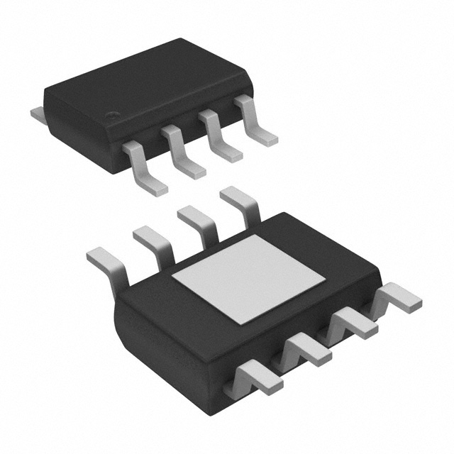
Small Outline Exposed Pad Plastic Package (EPSOIC).
• 40V tolerant logic level (TTL/CMOS) enable input
Applications
• Stable operation with 10µF output capacitor
• Low 26µVRMS noise
• Industrial
• 5kV ESD HBM rated
• Telecommunications
• Thermal shutdown and current limit protection
• 8 Ld exposed pad EPSOIC package
Related Literature
For a full list of related documents, visit our website:
• ISL80410 device page
25
VIN = 14V
CIN
0.1µF
VOUT = 12V
OUT
IN
R1
EN
EPAD
(GND)
ADJ
R2
GND
Figure 1. Typical Application
FN8983 Rev.2.00
Aug 8, 2019
COUT
10µF
Quiescent Current (µA)
20
15
10
5
0
-50
0
50
Temperature (°C)
100
150
Figure 2. Quiescent Current vs Temperature (at Unity
Gain), VIN = 14V
Page 1 of 12
�ISL80410
1.
1. Overview
Overview
1.1
Block Diagram
VIN
EN
Control
Logic
+
Thermal
Sensor
EA
FET Driver with
Current Limit
VOUT
Reference
and Soft-Start
ADJ
GND
Figure 3. Block Diagram
1.2
Ordering Information
Part Number
(Notes 2, 3)
Part
Marking
Temp. Range
(°C)
Enable
Pin
Output
Voltage (V)
Tape and Reel
(Units) (Note 1)
Yes
ADJ
-
Package
(RoHS Compliant)
8 Ld EPSOIC
Pkg.
Dwg. #
ISL80410IBEZ
80410 IBEZ
-40 to +125
M8.15B
ISL80410IBEZ-T
80410 IBEZ
-40 to +125
Yes
ADJ
2.5k
8 Ld EPSOIC
M8.15B
ISL80410IBEZ-T7A
80410 IBEZ
-40 to +125
Yes
ADJ
250
8 Ld EPSOIC
M8.15B
ISL80410EVAL1Z
Evaluation Platform
Notes:
1. See TB347 for details about reel specifications.
2. These Pb-free plastic packaged products employ special Pb-free material sets, molding compounds/die attach materials, and 100%
matte tin plate plus anneal (e3 termination finish, which is RoHS compliant and compatible with both SnPb and Pb-free soldering
operations). Pb-free products are MSL classified at Pb-free peak reflow temperatures that meet or exceed the Pb-free
requirements of IPC/JEDEC J STD-020.
3. For Moisture Sensitivity Level (MSL), see the ISL80410 device page. For more information about MSL, see TB363.
Table 1. Key Differences in Family of 40V LDO Parts
Part Number
Minimum IOUT
IC Package
ISL80410
150mA
8 Ld EPSOIC
ISL80136
50mA
8 Ld EPSOIC
ISL80138
150mA
14 LD HTSSOP
FN8983 Rev.2.00
Aug 8, 2019
Page 2 of 12
�ISL80410
1.3
1. Overview
Pin Configuration
8 Ld EPSOIC
Top View
IN
1
NC
2
8
OUT
7
ADJ
6
NC
5
GND
PAD
1.4
NC
3
EN
4
(GND)
Pin Descriptions
Pin Number
Pin Name
Description
1
IN
Input voltage pin. A minimum 0.1µF X5R/X7R capacitor is required for proper operation.
Range: 6V to 40V
2, 3, 6
NC
These pins have internal termination and can be left unconnected. Connection to ground is optional.
4
EN
Set this pin high to enable the device. Range: 0V to VIN
5
GND
Ground pin.
7
ADJ
This pin is connected to the external feedback resistor divider, which sets the LDO output voltage.
8
OUT
Regulated output voltage. A 10µF X5R/X7R output capacitor is required for stability. Range: 0V to 12V
-
PAD
It is recommended to solder the PAD to the ground plane.
FN8983 Rev.2.00
Aug 8, 2019
Page 3 of 12
�ISL80410
2.
2.1
2. Specifications
Specifications
Absolute Maximum Ratings
Parameter
Minimum
Maximum
Unit
IN Pin to GND Voltage
GND - 0.3
45
V
OUT Pin to GND Voltage
GND - 0.3
16
V
ADJ Pin to GND Voltage
GND - 0.3
3
V
EN Pin to GND Voltage
GND - 0.3
VIN
V
Output Short-Circuit Duration
ESD Rating
Human Body Model (Tested per JESD22-A114E)
Machine Model (Tested per JESD-A115-A)
Indefinite
-
Value
Unit
5
kV
200
V
Charge Device Model (Tested per JESD22-C101C)
2.2
kV
Latch-up (Tested per JESD78B; Class II, Level A)
100
mA
CAUTION: Do not operate at or near the maximum ratings listed for extended periods of time. Exposure to such conditions can
adversely impact product reliability and result in failures not covered by warranty.
2.2
Thermal Information
Thermal Resistance (Typical)
8 Ld EPSOIC Package (Notes 4, 5)
JA (°C/W)
JC (°C/W)
50
9
Notes:
4. JA is measured in free air with the component mounted on a high-effective thermal conductivity test board with “direct attach”
features. See TB379 for more information.
5. For JC, the “case temp” location is the center of the exposed metal pad on the package underside.
Parameter
Minimum
Maximum Junction Temperature
Maximum Storage Temperature Range
-65
Pb-Free Reflow Profile
2.3
Maximum
Unit
+150
°C
+175
°C
See TB493
Recommended Operating Conditions
Parameter
Minimum
Maximum
Unit
Ambient Temperature Range
-40
+125
°C
IN pin to GND Voltage
+6
+40
V
+2.5
12
V
0
40
V
OUT pin to GND Voltage
EN pin to GND Voltage
FN8983 Rev.2.00
Aug 8, 2019
Page 4 of 12
�ISL80410
2.4
2. Specifications
Electrical Specifications
Recommended Operating Conditions, unless otherwise noted. VIN = 14V, IOUT = 1mA, TA = TJ = -40°C to +125°C, unless otherwise
noted. Typical specifications are at TA = +25°C. Boldface limits apply across the operating temperature range, -40°C to +125°C.
Parameter
Symbol
Test Conditions
VIN
Guaranteed Output
Current
IOUT
VIN = VOUT + VDO
ADJ Reference Voltage
VOUT
EN = High, VIN = 14V,
IOUT = 0.1mA to 150mA
(VOUT low line - VOUT high line)
/VOUT low line
Load Regulation
(VOUT no load - VOUT high load) VIN = 14V, IOUT = 100µA to 150mA
/VOUT no load
1.211
IOUT = 1mA, VOUT = 2.5V
IOUT = 150mA, VOUT = 2.5V
IOUT = 1mA, VOUT = 5V
ISHDN
Quiescent Current
IQ
Power Supply Rejection
Ratio
PSRR
Output Voltage Noise
Unit
40
V
mA
1.223
1.235
V
0.04
0.15
%
0.3
0.6
%
7
33
mV
380
610
mV
7
33
mV
295
545
mV
EN = LOW
2
3.64
µA
EN = HIGH, IOUT = 0mA
18
24
µA
EN = HIGH, IOUT = 1mA
22
42
µA
EN = HIGH, IOUT = 10mA
34
60
µA
EN = HIGH, IOUT = 150mA
90
125
µA
f = 100Hz; VIN_RIPPLE = 500mVP-P;
Load = 150mA
66
dB
VIN = 14V, VOUT = 3.3V,
COUT = 10µF, IOUT = 10mA,
BW = 100Hz to 100kHz
26
µVRMS
IOUT = 150mA, VOUT = 5V
Shutdown Current
Max
(Note 8)
150
6V < VIN 40V, IOUT = 1mA
Line Regulation
VDO
Typ
6
Input Voltage Range
Dropout Voltage (Note 6)
Min
(Note 8)
EN Function
EN Threshold Voltage
VEN_H
VOUT = Off to On
VEN_L
VOUT = On to Off
EN Pin Current
IEN
EN to Regulation Time
(Note 7)
tEN
1.485
0.975
VOUT = 0V
V
V
0.026
1.65
µA
1.93
ms
Protection Features
Output Current Limit
ILIMIT
VOUT = 0V
Thermal Shutdown
TSHDN
Junction Temperature Rising
Thermal Shutdown
Hysteresis
THYST
175
410
mA
+165
°C
+20
°C
Notes:
6. Dropout voltage is defined as (VIN - VOUT) when VOUT is 2% below the value of VOUT.
7. Enable to Regulation Time is the time the output takes to reach 95% of its final value with VIN = 14V. EN is taken from VIL to VIH in
5ns. For the adjustable versions, the output voltage is set at 5V.
8. Parameters with MIN and/or MAX limits are 100% tested at +25°C, unless otherwise specified. Temperature limits established by
characterization and are not production tested.
FN8983 Rev.2.00
Aug 8, 2019
Page 5 of 12
�ISL80410
3.
3. Typical Performance Curves
Typical Performance Curves
VIN = 14V, IOUT = 1mA, VOUT = 5V, TJ = +25°C, unless otherwise specified.
120
30
+125°C
25
+125°C
Quiescent Current (µA)
Quiescent Current (µA)
100
80
60
-40°C
40
+25°C
20
+25°C
-40°C
15
10
5
0
0
50
100
Load Current (mA)
0
150
Figure 4. Quiescent Current vs Load Current
0
10
20
Input Voltage (V)
30
40
Figure 5. Quiescent Current vs Input Voltage (No Load)
3.0
0.010
Output Voltage Variation (%)
2.5
Shutdown Current (µA)
20
VIN = 40V
2.0
1.5
VIN = 14V
1.0
0.5
0
-50
0
50
Temperature (°C)
100
150
0.005
VOUT = 5V
0
-0.005
-0.010
-50
VOUT = 3.3V
0
50
Temperature (°C)
100
150
Figure 7. Output Voltage vs Temperature (Load = 50mA)
Figure 6. Shutdown Current vs Temperature (EN = 0)
5.20
500mV/Div
5.15
EN
Output Voltage (V)
5.10
1V/Div
+125°C
5.05
+25°C
5.00
VOUT
4.95
TIME = 500µs/Div
-40°C
4.90
4.85
4.80
0
50
100
Load Current (mA)
Figure 8. Output Voltage vs Load Current
FN8983 Rev.2.00
Aug 8, 2019
150
Figure 9. Start-Up Waveform
Page 6 of 12
�ISL80410
3. Typical Performance Curves
VIN = 14V, IOUT = 1mA, VOUT = 5V, TJ = +25°C, unless otherwise specified. (Continued)
70
Time = 5ms/Div
60
VOUT = 3.3V
VOUT
PSRR (dB)
50
100mV/Div
50mA
IOUT
40
VOUT = 5V
30
20
0mA
10
0
100
Figure 10. Load Transient Response
1k
10k
Frequency (Hz)
100k
1M
Figure 11. PSRR vs Frequency for Various Output
Voltages, (Load = 150mA)
10
90
80
70
IOUT = 0A
Noise (µV/√Hz)
PSRR (dB)
60
50
IOUT = 75mA
40
30
1
0.1
IOUT = 150mA
20
10
0
100
1k
10k
100k
1M
0.01
10
VIN = 14V
VOUT = 3.3V
COUT = 10µF
IOUT = 10mA
100
Frequency (Hz)
1k
Frequency (Hz)
10k
100k
BW = 100 < f < 100kHz output noise voltage ~ 26μVrms
Figure 12. PSRR vs Frequency for Various Load
Currents, VOUT = 3.3V
Figure 13. Output Noise Spectral Density, IOUT = 10mA
10
Noise (µV/√Hz)
1
0.1
0.01
10
VIN = 14V
VOUT = 3.3V
COUT = 10µF
IOUT = 150mA
100
1k
10k
Frequency (Hz)
BW = 100 < f < 100kHz output noise voltage ~ 38μVrms
100k
Figure 14. Output Noise Spectral Density, IOUT = 150mA
FN8983 Rev.2.00
Aug 8, 2019
Page 7 of 12
�ISL80410
4.
4. Functional Description
Functional Description
4.1
Functional Overview
The ISL80410 is a high performance, high voltage, Low-Dropout regulator (LDO) with 150mA sourcing
capability. The part is rated to operate across the -40°C to +125°C temperature range. Its ultra low quiescent current
makes it an ideal choice for “always-on” applications. It works well under a “load dump condition” in which the
input voltage could rise up to 40V. This LDO device also features current limit and thermal shutdown protection.
4.2
Enable Control
The ISL80410 has an enable pin, which turns the device on when pulled high. When EN is low, the IC goes into
shutdown mode and draws less than 2µA of current. Tie the EN pin directly to IN for “always-on” operation.
4.3
Current Limit Protection
The ISL80410 has internal current limiting functionality to protect the regulator during fault conditions. During
current limit, the output sources a fixed amount of current largely independent of the output voltage. If the short or
overload is removed from VOUT, the output returns to normal voltage regulation mode.
4.4
Thermal Fault Protection
If the die temperature exceeds a typical value of +165°C, the output of the LDO shuts down until the die
temperature cools to a typical value of +145°C. The level of power dissipated, combined with the ambient
temperature and the thermal impedance of the package, determines if the junction temperature exceeds the thermal
shutdown temperature. See “Power Dissipation” on page 9 for more details.
FN8983 Rev.2.00
Aug 8, 2019
Page 8 of 12
�ISL80410
5.
5. Application Information
Application Information
5.1
Input and Output Capacitors
A minimum 0.1µF ceramic capacitor is recommended at the input for proper operation. For the output, a ceramic
capacitor with a capacitance of 10µF is recommended for the ISL80410 to maintain stability. Route the ground
connection of the output capacitor directly to the GND pin of the device and place it close to the IC.
5.2
Output Voltage Setting
The ISL80410 output voltage is programmed using an external resistor divider as shown in Figure 15.
OUT
IN
CIN
0.1µF
R1
EN
COUT
10µF
ADJ
R2
GND
Figure 15. Output Voltage Setting
The output voltage is calculated using Equation 1:
R
V OUT = 1.223V ------1- + 1
R
2
(EQ. 1)
5.3
Power Dissipation
The junction temperature must not exceed the range specified in “Recommended Operating Conditions” on page 4.
The power dissipation can be calculated using Equation 2:
P D = V IN – V OUT I OUT + V IN I GND
(EQ. 2)
The maximum allowable junction temperature, TJ(MAX), and the maximum expected ambient temperature, TA(MAX),
determine the maximum allowable junction temperature rise (TJ), as shown in Equation 3:
(EQ. 3)
T J = T J MAX – T A MAX
To calculate the maximum ambient operating temperature, use the junction-to-ambient thermal resistance (JA) as
shown in Equation 4:
(EQ. 4)
5.4
T J MAX = P D MAX x JA + T A
Board Layout Recommendations
A good Printed Circuit Board (PCB) layout is important to achieve expected performance. When placing the
components and routing the trace, minimize the ground impedance and keep the parasitic inductance low. The input
and output capacitors should have a good ground connection and be placed as close to the IC as possible. The
feedback trace in the adjustable version should be away from other noisy traces. Connect the exposed pad to the
ground plane using as many vias as possible within the pad for the best thermal relief.
FN8983 Rev.2.00
Aug 8, 2019
Page 9 of 12
�ISL80410
6.
6. Revision History
Revision History
Rev.
Date
Description
2.00
Aug 8, 2019
Updated POD to the latest revision. Changes are as follows:
-Updated L Millimeter minimum in detail A from 0.41 to 0.406.
-Updated the following in the Side View:
-Changed total package height Millimeter MIN and MAX values from: 1.43 MIN and 1.68 MAX to:
1.422 MIN and 1.700 MAX and Inches max from 0.066 to 0.067.
-Changed A1 Inches MIN from: 0.001 to 0.0, and A1 Millimeters MIN from 0.03 to 0.0
1.00
Feb 8, 2019
Updated title
Updated the 6th bullet and added the 8th bullet in the features list.
Updated Related Literature section.
Updated ordering information table with tape and reel information and updated notes.
Added Output Voltage Noise specification.
0.00
Jan 24, 2018
Initial release.
FN8983 Rev.2.00
Aug 8, 2019
Page 10 of 12
�ISL80410
7.
Package Outline Drawing
7. Package Outline Drawing
For the most recent package outline drawing, see M8.15B.
M8.15B
8 Lead Narrow Body Small Outline Exposed Pad Plastic Package
Rev 7, 5/19
FN8983 Rev.2.00
Aug 8, 2019
Page 11 of 12
�1RWLFH
��
'HVFULSWLRQV�RI�FLUFXLWV��VRIWZDUH�DQG�RWKHU�UHODWHG�LQIRUPDWLRQ�LQ�WKLV�GRFXPHQW�DUH�SURYLGHG�RQO\�WR�LOOXVWUDWH�WKH�RSHUDWLRQ�RI�VHPLFRQGXFWRU�SURGXFWV�
DQG�DSSOLFDWLRQ�H[DPSOHV��