To our customers,
Old Company Name in Catalogs and Other Documents
On April 1st, 2010, NEC Electronics Corporation merged with Renesas Technology
Corporation, and Renesas Electronics Corporation took over all the business of both
companies. Therefore, although the old company name remains in this document, it is a valid
Renesas Electronics document. We appreciate your understanding.
Renesas Electronics website: http://www.renesas.com
April 1st, 2010
Renesas Electronics Corporation
Issued by: Renesas Electronics Corporation (http://www.renesas.com)
Send any inquiries to http://www.renesas.com/inquiry.
�Notice
1.
2.
3.
4.
5.
6.
7.
All information included in this document is current as of the date this document is issued. Such information, however, is
subject to change without any prior notice. Before purchasing or using any Renesas Electronics products listed herein, please
confirm the latest product information with a Renesas Electronics sales office. Also, please pay regular and careful attention to
additional and different information to be disclosed by Renesas Electronics such as that disclosed through our website.
Renesas Electronics does not assume any liability for infringement of patents, copyrights, or other intellectual property rights
of third parties by or arising from the use of Renesas Electronics products or technical information described in this document.
No license, express, implied or otherwise, is granted hereby under any patents, copyrights or other intellectual property rights
of Renesas Electronics or others.
You should not alter, modify, copy, or otherwise misappropriate any Renesas Electronics product, whether in whole or in part.
Descriptions of circuits, software and other related information in this document are provided only to illustrate the operation of
semiconductor products and application examples. You are fully responsible for the incorporation of these circuits, software,
and information in the design of your equipment. Renesas Electronics assumes no responsibility for any losses incurred by
you or third parties arising from the use of these circuits, software, or information.
When exporting the products or technology described in this document, you should comply with the applicable export control
laws and regulations and follow the procedures required by such laws and regulations. You should not use Renesas
Electronics products or the technology described in this document for any purpose relating to military applications or use by
the military, including but not limited to the development of weapons of mass destruction. Renesas Electronics products and
technology may not be used for or incorporated into any products or systems whose manufacture, use, or sale is prohibited
under any applicable domestic or foreign laws or regulations.
Renesas Electronics has used reasonable care in preparing the information included in this document, but Renesas Electronics
does not warrant that such information is error free. Renesas Electronics assumes no liability whatsoever for any damages
incurred by you resulting from errors in or omissions from the information included herein.
Renesas Electronics products are classified according to the following three quality grades: “Standard”, “High Quality”, and
“Specific”. The recommended applications for each Renesas Electronics product depends on the product’s quality grade, as
indicated below. You must check the quality grade of each Renesas Electronics product before using it in a particular
application. You may not use any Renesas Electronics product for any application categorized as “Specific” without the prior
written consent of Renesas Electronics. Further, you may not use any Renesas Electronics product for any application for
which it is not intended without the prior written consent of Renesas Electronics. Renesas Electronics shall not be in any way
liable for any damages or losses incurred by you or third parties arising from the use of any Renesas Electronics product for an
application categorized as “Specific” or for which the product is not intended where you have failed to obtain the prior written
consent of Renesas Electronics. The quality grade of each Renesas Electronics product is “Standard” unless otherwise
expressly specified in a Renesas Electronics data sheets or data books, etc.
“Standard”:
8.
9.
10.
11.
12.
Computers; office equipment; communications equipment; test and measurement equipment; audio and visual
equipment; home electronic appliances; machine tools; personal electronic equipment; and industrial robots.
“High Quality”: Transportation equipment (automobiles, trains, ships, etc.); traffic control systems; anti-disaster systems; anticrime systems; safety equipment; and medical equipment not specifically designed for life support.
“Specific”:
Aircraft; aerospace equipment; submersible repeaters; nuclear reactor control systems; medical equipment or
systems for life support (e.g. artificial life support devices or systems), surgical implantations, or healthcare
intervention (e.g. excision, etc.), and any other applications or purposes that pose a direct threat to human life.
You should use the Renesas Electronics products described in this document within the range specified by Renesas Electronics,
especially with respect to the maximum rating, operating supply voltage range, movement power voltage range, heat radiation
characteristics, installation and other product characteristics. Renesas Electronics shall have no liability for malfunctions or
damages arising out of the use of Renesas Electronics products beyond such specified ranges.
Although Renesas Electronics endeavors to improve the quality and reliability of its products, semiconductor products have
specific characteristics such as the occurrence of failure at a certain rate and malfunctions under certain use conditions. Further,
Renesas Electronics products are not subject to radiation resistance design. Please be sure to implement safety measures to
guard them against the possibility of physical injury, and injury or damage caused by fire in the event of the failure of a
Renesas Electronics product, such as safety design for hardware and software including but not limited to redundancy, fire
control and malfunction prevention, appropriate treatment for aging degradation or any other appropriate measures. Because
the evaluation of microcomputer software alone is very difficult, please evaluate the safety of the final products or system
manufactured by you.
Please contact a Renesas Electronics sales office for details as to environmental matters such as the environmental
compatibility of each Renesas Electronics product. Please use Renesas Electronics products in compliance with all applicable
laws and regulations that regulate the inclusion or use of controlled substances, including without limitation, the EU RoHS
Directive. Renesas Electronics assumes no liability for damages or losses occurring as a result of your noncompliance with
applicable laws and regulations.
This document may not be reproduced or duplicated, in any form, in whole or in part, without prior written consent of Renesas
Electronics.
Please contact a Renesas Electronics sales office if you have any questions regarding the information contained in this
document or Renesas Electronics products, or if you have any other inquiries.
(Note 1) “Renesas Electronics” as used in this document means Renesas Electronics Corporation and also includes its majorityowned subsidiaries.
(Note 2) “Renesas Electronics product(s)” means any product developed or manufactured by or for Renesas Electronics.
�M32C/84 Group (M32C/84, M32C/84T)
SINGLE-CHIP 16/32-BIT CMOS MICROCOMPUTER
REJ03B0047-0121
Rev.1.21
Jul. 08, 2005
1. Overview
The M32C/84 group (M32C/84, M32C/84T) microcomputer is a single-chip control unit that utilizes highperformance silicon gate CMOS technology with the M32C/80 series CPU core. The M32C/84 group
(M32C/84, M32C/84T) is available in 144-pin and 100-pin plastic molded LQFP/QFP packages.
With a 16-Mbyte address space, this microcomputer combines advanced instruction manipulation capabilities to process complex instructions by less bytes and execute instructions at higher speed.
It includes a multiplier and DMAC adequate for office automation, communication devices and industrial
equipments, and other high-speed processing applications.
1.1 Applications
Automobiles, audio, cameras, office equipment, communications equipment, portable equipment, etc.
Rev. 1.21 Jul. 08, 2005
Page 1 of 85
�M32C/84 Group (M32C/84, M32C/84T)
1. Overview
1.2 Performance Overview
Tables 1.1 and 1.2 list performance overview of the M32C/84 group (M32C/84, M32C/84T).
Table 1.1 M32C/84 Group (M32C/84, M32C/84T) Performance (144-Pin Package)
Characteristic
Performance
M32C/84
M32C/84T
CPU
Basic Instructions
108 instructions
Shortest Instruction Execution Time 31.3 ns
31.3 ns
(f(BCLK)=32 MHz, VCC1=4.2 V to 5.5 V) (f(BCLK)=32 MHz, VCC1=4.2 V to 5.5 V)
41.7 ns
(f(BCLK)=24 MHz, VCC1=3.0 V to 5.5 V)
Operation Mode
Single-chip mode, Memory expansion Single-chip mode
mode and Microprocessor mode
Address Space
16 Mbytes
Memory Capacity
See Table 1.3
Peripheral I/O Port
123 I/O pins and 1 input pin
Function Multifunction Timer
Timer A: 16 bits x 5 channels, Timer B: 16 bits x 6 channels
Three-phase motor control circuit
Intelligent I/O
Time measurement function or Waveform generating function:
16 bits x 8 channels
Communication function (Clock synchronous serial I/O, Clock asynchronous serial I/O, HDLC data processing)
Serial I/O
5 Channels
Clock synchronous serial I/O, Clock asynchronous serial I/O,
IEBus(1), I2C bus(2)
CAN Module
1 channel Supporting CAN 2.0B specification
A/D Converter
10-bit A/D converter: 1 circuit, 34 channels
D/A Converter
8 bits x 2 channels
DMAC
4 channels
DMAC II
Can be activated by all peripheral function interrupt sources
Immediate transfer, Calculation transfer and Chain transfer functions
CRC Calculation Circuit
CRC-CCITT
X/Y Converter
16 bits x 16 bits
Watchdog Timer
15 bits x 1 channel (with prescaler)
Interrupt
38 internal and 8 external sources, 5 software sources
Interrupt priority level: 7
Clock Generation Circuit
4 circuits
Main clock oscillation circuit(*), Sub clock oscillation circuit(*), On-chip
oscillator, PLL frequency synthesizer
(*)Equipped with a built-in feedback resistor. Ceramic resonator or
crystal oscillator must be connected externally
Oscillation Stop Detect Function
Main clock oscillation stop detect function
Voltage Detection Circuit
Available (optional)
Not available(4)
Electrical Supply Voltage
VCC1=4.2 V to 5.5 V, VCC2=3.0 V to VCC1 VCC1=VCC2=4.2 V to 5.5 V,
Charact(f(BCLK)=32 MHz)
(f(BCLK)=32 MHz)(3)
eristics
VCC1=3.0 V to 5.5 V, VCC2=3.0 V to VCC1
(f(BCLK)=24 MHz)
Power Consumption
28 mA (VCC1=VCC2=5 V,
28 mA (VCC1=VCC2=5 V,
f(BCLK)=32 MHz)
f(BCLK)=32 MHz)
10µA (VCC1=VCC2=5 V,
22 mA (VCC1=VCC2=3.3 V,
f(BCLK)=24 MHz)
f(BCLK)=32 kHz, in wait mode)
10µA (VCC1=VCC2=5 V,
f(BCLK)=32 kHz, in wait mode)
Flash
Program/Erase Supply Voltage
3.3 V ± 0.3 V or 5.0 V ± 0.5 V
5.0 V ± 0.5 V
Memory Program and Erase Endurance
100 times (all space)
–40 to 85oC (T version)
Operating Ambient Temperature
–20 to 85oC
–40 to 85oC (optional)
Package
144-pin plastic molded LQFP
NOTES:
1. IEBus is a trademark of NEC Electronics Corporation.
2. I2C bus is a trademark of Koninklijke Philips Electronics N. V.
3. The supply voltage of M32C/84T (High-reliability version) must be VCC1=VCC2.
4. The cold start-up/warm start-up determine function is available only at the user's option.
All options are on a request basis.
Rev. 1.21 Jul. 08, 2005
Page 2 of 85
�M32C/84 Group (M32C/84, M32C/84T)
1. Overview
Table 1.2 M32C/84 Group (M32C/84, M32C/84T) Performance (100-Pin Package)
Characteristic
Performance
M32C/84
M32C/84T
CPU
Basic Instructions
108 instructions
Shortest Instruction Execution Time 31.3 ns
31.3 ns
(f(BCLK)=32 MHz, VCC1=4.2 V to 5.5 V) (f(BCLK)=32 MHz, VCC1=4.2 V to 5.5 V)
41.7 ns
(f(BCLK)=24 MHz, V CC1=3.0 V to 5.5 V)
Operation Mode
Single-chip mode, Memory expansion Single-chip mode
mode and Microprocessor mode
Address Space
16 Mbytes
Memory Capacity
See Table 1.3
Peripheral I/O Port
87 I/O pins and 1 input pin
Function Multifunction Timer
Timer A: 16 bits x 5 channels, Timer B: 16 bits x 6 channels
Three-phase motor control circuit
Intelligent I/O
Time measurement function or Waveform generating function:
16 bits x 8 channels
Communication function (Clock synchronous serial I/O, Clock asynchronous serial I/O, HDLC data processing)
Serial I/O
5 Channels
Clock synchronous serial I/O, Clock asynchronous serial I/O,
IEBus(1), I2C bus(2)
CAN Module
1 channel Supporting CAN 2.0B specification
A/D Converter
10-bit A/D converter: 1 circuit, 26 channels
D/A Converter
8 bits x 2 channels
DMAC
4 channels
DMAC II
Can be activated by all peripheral function interrupt sources
Immediate transfer, Calculation transfer and Chain transfer functions
CRC Calculation Circuit
CRC-CCITT
X/Y Converter
16 bits x 16 bits
Watchdog Timer
15 bits x 1 channel (with prescaler)
Interrupt
38 internal and 8 external sources, 5 software sources
Interrupt priority level: 7
Clock Generation Circuit
4 circuits
Main clock oscillation circuit(*), Sub clock oscillation circuit(*), On-chip
oscillator, PLL frequency synthesizer
(*)Equipped with a built-in feedback resistor. Ceramic resonator or
crystal oscillator must be connected externally
Oscillation Stop Detect Function
Main clock oscillation stop detect function
Voltage Detection Circuit
Available (optional)
Not available(4)
Electrical Supply Voltage
VCC1=4.2 V to 5.5 V, VCC2=3.0 V to VCC1 VCC1=VCC2=4.2 V to 5.5 V,
Charact(f(BCLK)=32 MHz)
(f(BCLK)=32 MHz)(3)
eristics
VCC1=3.0 V to 5.5 V, VCC2=3.0 V to VCC1
(f(BCLK)=24 MHz)
28 mA (VCC1=VCC2=5 V,
Power Consumption
28 mA (VCC1=VCC2=5 V,
f(BCLK)=32 MHz)
f(BCLK)=32 MHz)
22 mA (VCC1=VCC2=3.3 V,
10µA (VCC1=VCC2=5 V,
f(BCLK)=24 MHz)
f(BCLK)=32 kHz, in wait mode)
10µA (VCC1=VCC2=5 V,
f(BCLK)=32 kHz, in wait mode)
Flash
Program/Erase Supply Voltage
3.3 V ± 0.3 V or 5.0 V ± 0.5 V
5.0 V ± 0.5 V
Memory Program and Erase Endurance
100 times (all space)
Operating Ambient Temperature
–20 to 85oC
–40 to 85oC (T version)
o
–40 to 85 C (optional)
Package
100-pin plastic molded LQFP/QFP
NOTES:
1. IEBus is a trademark of NEC Electronics Corporation.
2. I2C bus is a trademark of Koninklijke Philips Electronics N. V.
3. The supply voltage of M32C/84T (High-reliability version) must be VCC1=VCC2.
4. The cold start-up/warm start-up determine function is available only at the user's option.
All options are on a request basis.
Rev. 1.21 Jul. 08, 2005
Page 3 of 85
�1. Overview
M32C/84 Group (M32C/84, M32C/84T)
1.3 Block Diagram
Figure 1.1 shows a block diagram of the M32C/84 group (M32C/84, M32C/84T) microcomputer.
8
8
8
8
8
8
Port P0
Port P1
Port P2
Port P3
Port P4
Port P5
8
Port P6
Peripheral Functions
DMAC
DMACII
CRC Calculation Circuit (CCITT):
X16+X12+X5+1
INTB
ISP
R3
USP
A0
Port P14
7
SVF
FB
SVP
SB
VCT
Port P15
Port P11
8
5
Port P12
8
Port P13
8
(Note 1)
NOTES:
1. Ports P11 to P15 are provided in the 144-pin package only.
2. Included in the 144-pin package only.
3. The supply voltage of M32C/84T (High-reliability version) must be VCC1=VCC2.
Figure 1.1 M32C/84 Group (M32C/84, M32C/84T) Block Diagram
Rev. 1.21 Jul. 08, 2005
Page 4 of 85
RAM
PC
A1
ROM
Multiplier
8
R1L
R2
8
R1H
Memory
FLG
Port P10
R0L
Port P9
Time Measurement: 8 channels
Waveform Generating: 8 channels
Communication Functions:
Clock Synchronous Serial I/O, UART,
HDLC Data Processing
R0H
P85
M32C/80 series CPU Core
Intelligent I/O
CAN Module: 1 channel
7
X/Y Converter:
16 bits x 16 bits
D/A Converter:
8 bits x 2 channels
Port P8
Watchdog Timer (15 bits)
8
UART/Clock Synchronous Serial I/O:
5 channels
Three-Phase Motor Control Circuit
Port P7
Clock Generation Circuit
XIN - XOUT
XCIN - XCOUT
On-chip Oscillator
PLL Frequency Synthesizer
A/D Converter:
1 circuit
Standard: 10 inputs
Maximum: 34 inputs(2)
Timer (16 bits)
Timer A: 5 channels
Timer B: 6 channels
�1. Overview
M32C/84 Group (M32C/84, M32C/84T)
1.4 Product Information
Table 1.3 lists product information. Figure 1.2 shows the product numbering system.
Table 1.3 M32C/84 Group (1) (M32C/84)
Type Number
Package
M30845FJGP
PLQP0144KA-A (144P6Q-A)
M30843FJGP
PLQP0100KB-A (100P6Q-A)
M30843FJFP
PRQP0100JB-A (100P6S-A)
M30845FHGP
PLQP0144KA-A (144P6Q-A)
M30843FHGP
PLQP0100KB-A (100P6Q-A)
M30843FHFP
PRQP0100JB-A (100P6S-A)
M30845FWGP
PLQP0144KA-A (144P6Q-A)
M30843FWGP
PLQP0100KB-A (100P6Q-A)
M30845MW-XXXGP
PLQP0144KA-A (144P6Q-A)
M30843MW-XXXGP
PLQP0100KB-A (100P6Q-A)
M30843MW-XXXFP
PRQP0100JB-A (100P6S-A)
M30842ME-XXXGP
PLQP0144KA-A (144P6Q-A)
M30840ME-XXXGP
PLQP0100KB-A (100P6Q-A)
M30840ME-XXXFP
PRQP0100JB-A (100P6S-A)
M30842MC-XXXGP
PLQP0144KA-A (144P6Q-A)
M30840MC-XXXGP
PLQP0100KB-A (100P6Q-A)
M30840MC-XXXFP
PRQP0100JB-A (100P6S-A)
As of July, 2005
ROM
Capacity
RAM
Capacity
Remarks
512K+4K
Flash Memory
384K+4K
24K
320K+4K
320K
192K
1 6K
Mask ROM
128K
10K
M30842SGP
(D)
PLQP0144KA-A (144P6Q-A)
M30840SGP
(D)
PLQP0100KB-A (100P6Q-A)
M30840SFP
(D)
PRQP0100JB-A (100P6S-A)
---
ROMless
(D): Under Development
Table 1.3 M32C/84 Group (2) (T Version, M32C/84T)
Type Number
Package
M30845FJTGP
PLQP0144KA-A (144P6Q-A)
M30843FJTGP
PLQP0100KB-A (100P6Q-A)
M30845FHTGP
PLQP0144KA-A (144P6Q-A)
As of July, 2005
ROM
Capacity
RAM
Capacity
Remarks
24K
Flash Memory
T Version
(High-releability
85° C Version)
1 0K
Mask ROM
512K+4K
384K+4K
M30843FHTGP
PLQP0100KB-A (100P6Q-A)
M30843FWTGP
PLQP0100KB-A (100P6Q-A)
M30842MCT-XXXGP
(D)
PLQP0144KA-A (144P6Q-A)
M30840MCT-XXXGP
(D)
PLQP0100KB-A (100P6Q-A)
320K+4K
128K
(D): Under Development
Rev. 1.21 Jul. 08, 2005
Page 5 of 85
�1. Overview
M32C/84 Group (M32C/84, M32C/84T)
M30 84 5 M W
-XXX GP
Package Type:
FP = Package PRQP0100JB-A (100P6S-A)
GP = Package PLQP0100KB-A (100P6Q-A)
Package PLQP0144KA-A (144P6Q-A)
ROM Number:
Omitted in the Flash Memory Version
Classification:
Blank = General Industrial Use
T = T Version
ROM Capacity:
C = 128 Kbytes
E = 192 Kbytes
W = 320 Kbytes
H = 384 Kbytes
J = 512 Kbytes
Memory Type:
M = Mask ROM Version
F = Flash Memory Version
S = ROMless Version
RAM Capacity, Pin Count, etc
M32C/84 Group
M16C Family
Figure 1.2 Product Numbering System
Rev. 1.21 Jul. 08, 2005
Page 6 of 85
�1. Overview
M32C/84 Group (M32C/84, M32C/84T)
1.5 Pin Assignments and Descriptions
73
74
75
76
77
78
79
80
81
82
83
84
85
86
87
88
89
90
91
92
93
94
95
96
97
98
99
100
101
102
103
104
105
106
109
72
110
111
71
70
112
69
113
68
114
67
115
66
116
65
117
64
118
63
119
62
120
61
121
60
122
59
123
58
124
57
M32C/84 GROUP
(3)
(M32C/84, M32C/84T)
125
126
127
128
56
55
54
53
129
52
130
51
131
50
132
49
133
48
134
47
135
46
136
45
137
44
138
43
139
42
140
41
141
40
142
39
36
35
34
33
32
31
30
29
28
27
26
25
24
23
37
22
21
20
19
18
17
16
14
13
12
11
9
10
8
7
6
5
4
3
38
P44 / CS3 / A20
P45 / CS2 / A21
P46 / CS1 / A22
P47 / CS0 / A23
P125
P126
P127
P50 / WRL / WR
P51 / WRH / BHE
P52 / RD
P53 / CLKOUT / BCLK / ALE
P130
P131
Vcc2
P132
Vss
P133
P54 / HLDA / ALE
P55 / HOLD
P56 / ALE
P57 / RDY
P134
P135
P136
P137
P60 / CTS0 / RTS0 / SS0
P61 / CLK0
P62 / RxD0 / SCL0 / STxD0
P63 / TxD0 / SDA0 / SRxD0
P64 / CTS1 / RTS1 / SS1
P65 / CLK1
Vss
P66 / RxD1 / SCL1 / STxD1
Vcc1
P67 / TxD1 / SDA1 / SRxD1
(1, 2)
P70
SRxD4 / SDA4 / TxD4 / ANEX1 / P96
CLK4 / ANEX0 / P95
SS4 / RTS4 / CTS4 / TB4IN / DA1 / P94
SS3 / RTS3 / CTS3 / TB3IN / DA0 / P93
SRxD3 / SDA3 / TxD3 / TB2IN / P92
STxD3 / SCL3 / RxD3 / TB1IN / P91
CLK3 / TB0IN / P90
P146
P145
P144
OUTC17 / INPC17 / P143
OUTC16 / INPC16 / P142
OUTC15 / INPC15 / P141
OUTC14 / INPC14 / P140
BYTE
CNVss
XCIN / P87
XCOUT / P86
RESET
XOUT
Vss
XIN
Vcc1
NMI / P85
INT2 / P84
CAN0IN / INT1 / P83
CAN0OUT / INT0 / P82
INPC15 / OUTC15 / U / TA4IN / P81
ISRxD0 / U / TA4OUT / P80
ISCLK0 / INPC14 / OUTC14 / CAN0IN / TA3IN / P77
ISTxD0 / INPC13 / OUTC13 / CAN0OUT / TA3OUT / P76
BE1IN / ISRxD1 / OUTC12 / INPC12 / W / TA2IN / P75
ISCLK1 / OUTC11 / INPC11 / W / TA2OUT / P74
BE1OUT / ISTxD1 / OUTC10 / INPC10 / SS2 / RTS2 / CTS2 / V / TA1IN / P73
CLK2 / V / TA1OUT / P72
(2)INPC17 / OUTC17 / STxD2 / SCL2 / RxD2 / TA0IN / TB5IN / P71
2
144
15
143
1
D8 / P10
AN07 / D7 / P07
AN06 / D6 / P06
AN05 / D5 / P05
AN04 / D4 / P04
P114
OUTC13 / INPC13 / P113
BE1IN / ISRxD1 / OUTC12 / INPC12 / P112
ISCLK1 / OUTC11 / INPC11 / P111
BE1OUT / ISTxD1 / OUTC10 / INPC10 / P110
AN03 / D3 / P03
AN02 / D2 / P02
AN01 / D1 / P01
AN00 / D0 / P00
AN157 / P157
AN156 / P156
AN155 / P155
AN154 / P154
AN153 / P153
ISRxD0 / AN152 / P152
ISCLK0 / AN151 / P151
Vss
ISTxD0 / AN150 / P150
Vcc1
KI3 / AN7 / P107
KI2 / AN6 / P106
KI1 / AN5 / P105
KI0 / AN4 / P104
AN3 / P103
AN2 / P102
AN1 / P101
AVss
AN0 / P100
VREF
AVcc
STxD4 / SCL4 / RxD4 / ADTRG / P97
107
108
P11 / D9
P12 / D10
P13 / D11
P14 / D12
P15 / D13 / INT3
P16 / D14 / INT4
P17 / D15 / INT5
P20 / A0 ( / D0 ) / AN20
P21 / A1 ( / D1 ) / AN21
P22 / A2 ( / D2 ) / AN22
P23 / A3 ( / D3 ) / AN23
P24 / A4 ( / D4 ) / AN24
P25 / A5 ( / D5 ) / AN25
P26 / A6 ( / D6 ) / AN26
P27 / A7 ( / D7 ) / AN27
Vss
P30 / A8 ( / D8 )
Vcc2
P120
P121
P122
P123
P124
P31 / A9 ( / D9 )
P32 / A10 ( / D10 )
P33 / A11 ( / D11 )
P34 / A12 ( / D12 )
P35 / A13 ( / D13 )
P36 / A14 ( / D14 )
P37 / A15 ( / D15 )
P40 / A16
P41 / A17
Vss
P42 / A18
Vcc2
P43 / A19
Figures 1.3 to 1.5 show pin assignments (top view).
NOTES:
1. P70 / TA0OUT / TxD2 / SDA2 / SRxD2 / INPC16 / OUTC16
2. P70 and P71 are ports for the N-channel open drain output.
3. The supply voltage of M32C/84T must be VCC1=VCC2.
Figure 1.3 Pin Assignment for 144-Pin Package
Rev. 1.21 Jul. 08, 2005
Page 7 of 85
PLQP0144KA-A
(144P6Q-A)
�1. Overview
M32C/84 Group (M32C/84, M32C/84T)
Table 1.4 Pin Characteristics for 144-Pin Package
Pin
No.
Control
Pin
Port
Interrupt
Pin
Timer Pin
UART/CAN Pin
Intelligent I/O Pin
Analog Pin Bus Control Pin(1)
1
P96
TxD4/SDA4/SRxD4
ANEX1
2
P95
P94
P93
CLK4
ANEX0
TB3IN
DA1
DA0
P92
TB2IN
CTS4/RTS4/SS4
CTS3/RTS3/SS3
TxD3/SDA3/SRxD3
P91
P90
P146
P145
P144
TB1IN
TB0IN
3
4
5
6
7
8
9
10
11
12
13
14
15 BYTE
16 CNVSS
17 XCIN
18 XCOUT
19 RESET
20 XOUT
TB4IN
RxD3/SCL3/STxD3
CLK3
INPC17/OUTC17
P143
P142
P141
P140
INPC16/OUTC16
INPC15/OUTC15
INPC14/OUTC14
P87
P86
21 VSS
22 XIN
23 VCC1
24
25
P85
P84
NMI
INT2
26
27
P83
P82
P81
P80
P77
P76
P75
P74
P73
P72
P71
P70
P67
INT1
INT0
28
29
30
31
32
33
34
35
36
37
38
39 VCC1
40
41 VSS
42
43
44
45
46
47
48
CAN0IN
CAN0OUT
TA4IN/U
TA4OUT/U
TA3IN
TA3OUT
TA2IN/W
TA2OUT/W
TA1IN/V
TA1OUT/V
TB5IN/TA0IN
TA0OUT
CAN0IN
CAN0OUT
CTS2/RTS2/SS2
CLK2
RxD2/SCL2/STxD2
TxD2/SDA2/SRxD2
TxD1/SDA1/SRxD1
P66
RxD1/SCL1/STxD1
P65
P64
P63
P62
P61
P60
P137
CLK1
CTS1/RTS1/SS1
TxD0/SDA0/SRxD0
RxD0/SCL0/STxD0
CLK0
CTS0/RTS0/SS0
NOTES:
1. Bus control pins in M32C/84T cannot be used.
Rev. 1.21 Jul. 08, 2005
Page 8 of 85
INPC15/OUTC15
ISRxD0
INPC14/OUTC14/ISCLK0
INPC13/OUTC13/ISTxD0
INPC12/OUTC12/ISRxD1/BE1IN
INPC11/OUTC11/ISCLK1
INPC10/OUTC10/ISTxD1/BE1OUT
INPC17/OUTC17
INPC16/OUTC16
�1. Overview
M32C/84 Group (M32C/84, M32C/84T)
Table 1.4 Pin Characteristics for 144-Pin Package (Continued)
Pin
No.
Control
Pin
Port
49
P136
50
P135
P134
51
52
53
UART/CAN Pin
Intelligent I/O Pin
Analog Pin
Bus Control Pin
RDY
ALE
P56
P55
HOLD
HLDA/ALE
P54
56
P133
57
VSS
58
59
VCC2
P132
60
61
62
63
P131
P130
64
65
P51
P50
66
67
68
69
P127
P126
CLKOUT/BCLK/ALE
P53
P52
RD
WRH/BHE
WRL/WR
P125
70
71
P47
P46
CS0/A23
CS1/A22
P45
CS2/A21
P44
CS3/A20
P43
A19
P42
A18
P41
A17
P40
A16
P37
P36
A15(/D15)
A14(/D14)
A13(/D13)
A12(/D12)
A11(/D11)
VCC2
VSS
P35
P34
82
83
84
85
86
87
88
89
90
91
92
93
94
95
96
Timer Pin
P57
54
55
72
73
74
75
76
77
78
79
80
81
Interrupt
Pin
P33
A10(/D10)
A9(/D9)
P32
P31
P124
P123
P122
P121
P120
VCC2
A8(/D8)
P30
VSS
P27
AN27
P26
P25
AN26
AN25
NOTES:
1. Bus control pins in M32C/84T cannot be used.
Rev. 1.21 Jul. 08, 2005
Page 9 of 85
A7(/D7)
A6(/D6)
A5(/D5)
�1. Overview
M32C/84 Group (M32C/84, M32C/84T)
Table 1.4 Pin Characteristics for 144-Pin Package (Continued)
Pin
No.
Control
Pin
97
98
99
100
101
Port
Interrupt
Pin
Timer Pin
UART/CAN Pin
Intelligent I/O Pin
Analog Pin
P24
AN24
P23
AN23
P22
P21
AN22
AN21
P20
AN20
Bus Control Pin(1)
A4(/D4)
A3(/D3)
A2(/D2)
A1(/D1)
A0(/D0)
102
103
104
P17
105
P14
P13
D12
D11
P12
P11
D10
D9
106
107
108
109
P16
P15
D15
INT5
INT4
INT3
D14
D13
P10
D8
110
111
112
P07
P06
AN07
AN06
D7
D6
P05
AN05
D5
113
114
P04
AN04
D4
P114
P113
INPC13/OUTC13
116
117
118
P112
P111
INPC12/OUTC12/ISRxD1/BE1IN
INPC11/OUTC11/ISCLK1
P110
INPC10/OUTC10/ISTxD1/BE1OUT
119
P03
P02
AN03
AN02
D3
D2
P01
P00
AN01
AN00
D1
D0
115
120
121
122
123
P157
AN157
124
125
126
P156
AN156
P155
P154
AN155
AN154
127
128
P153
129
130 VSS
131
132 VCC1
133
134
135
136
137
138
139
140 AVSS
141
142 VREF
143 AVCC
144
AN153
P152
P151
ISRxD0
ISCLK0
AN152
AN151
P150
ISTxD0
AN150
P107
P106
KI3
KI2
AN7
AN6
P105
KI1
AN5
P104
P103
KI0
AN4
AN3
P102
AN2
P101
AN1
P100
AN0
RxD4/SCL4/STxD4
P97
NOTES:
1. Bus control pins in M32C/84T cannot be used.
Rev. 1.21 Jul. 08, 2005
Page 10 of 85
ADTRG
�Rev. 1.21 Jul. 08, 2005
2. P70 and P71 are ports for the N-channel open drain output.
Figure 1.4 Pin Assignment for 100-Pin Package
Page 11 of 85
19
20
21
22
CAN0IN / INT1 / P83
CAN0OUT / INT0 / P82
OUTC15 / INPC15 / U / TA4IN / P81
ISRxD0 / U / TA4OUT / P80
30
18
INT2 / P84
(2)OUTC16 / INPC16 / SRxD2 / SDA2 / TxD2 / TA0OUT / P70
17
NMI / P85
29
16
Vcc1
(2)OUTC17 / INPC17 / STxD2 / SCL2 / RxD2 / TA0IN / TB5IN / P71
15
XIN
28
14
Vss
CLK2 / V / TA1OUT / P72
13
XOUT
27
12
RESET
BE1OUT / ISTxD1 / OUTC10 / INPC10 / SS2 / RTS2 / CTS2 / V / TA1IN / P73
11
XCOUT / P86
26
10
XCIN / P87
25
9
ISCLK1 / OUTC11 / INPC11 / W / TA2OUT / P74
8
BYTE
CNVss
BE1IN / ISRxD1 / OUTC12 / INPC12 / W / TA2IN / P75
7
CLK3 / TB0IN / P90
24
6
STxD3 / SCL3 / RxD3 / TB1IN / P91
23
1. P97 / ADTRG / RxD4 / SCL4 / STxD4
ISCLK0 / OUTC14 / INPC14 / CAN0IN / TA3IN / P77
NOTES:
ISTxD0 / OUTC13 / INPC13 / CAN0OUT / TA3OUT / P76
5
SRxD3 / SDA3 / TxD3 / TB2IN / P92
P97
4
(1)
SS3 / RTS3 / CTS3 / TB3IN / DA0 / P93
P47 / CS0 / A23
D3 / AN03 / P03
85
46
P50 / WRL / WR
D2 / AN02 / P02
86
45
P51 / WRH / BHE
D1 / AN01 / P01
87
44
P52 / RD
D0 / AN00 / P00
88
43
P53 / CLKOUT / BCLK / ALE
KI3 / AN7 / P107
89
KI2 / AN6 / P106
90
KI1 / AN5 / P105
91
KI0 / AN4 / P104
92
AN3 / P103
D4 / AN04 / P04
3
47
83
SS4 / RTS4 / CTS4 / TB4IN / DA1 / P94
P46 / CS1 / A22
84
D5 / AN05 / P05
2
P45 / CS2 / A21
48
82
1
P44 / CS3 / A20
49
81
D6 / AN06 / P06
CLK4 / ANEX0 / P95
50
D7 / AN07 / P07
SRxD4 / SDA4 / TxD4 / ANEX1 / P96
P34 / A12 ( / D12 )
P35 / A13 ( / D13 )
P36 / A14 ( / D14 )
P37 / A15 ( / D15 )
P40 / A16
P41 / A17
P42 / A18
P43 / A19
57
56
55
54
53
52
51
59
58
P32 / A10 ( / D10 )
P33 / A11 ( / D11 )
60
Vcc2
P30 / A8 ( / D8 )
P31 / A9 ( / D9 )
Vss
63
61
P27 / A7 ( / D7 ) / AN27
64
62
P26 / A6 ( / D6 ) / AN26
65
P24 / A4 ( / D4 ) / AN24
68
P25 / A5 ( / D5 ) / AN25
P23 / A3 ( / D3 ) / AN23
69
66
P22 / A2 ( / D2 ) / AN22
70
67
P20 / A0 ( / D0 ) / AN20
P21 / A1 ( / D1 ) / AN21
71
P17 / D15 / INT5
72
73
P14 / D12
76
P15 / D13 / INT3
P13 / D11
77
P16 / D14 / INT4
P12 / D10
78
74
P11 / D9
79
75
P10 / D8
80
M32C/84 Group (M32C/84, M32C/84T)
1. Overview
42
P54 / HLDA / ALE
41
P55 / HOLD
40
P56 / ALE
39
P57 / RDY
93
38
P60 / CTS0 / RTS0 / SS0
AN2 / P102
94
37
P61 / CLK0
AN1 / P101
95
36
P62 / RxD0 / SCL0 / STxD0
AVss
96
35
P63 / TxD0 / SDA0 / SRxD0
AN0 / P100
97
34
P64 / CTS1 / RTS1 / SS1
VREF
98
33
P65 / CLK1
AVcc
99
32
P66 / RxD1 / SCL1 / STxD1
31
P67 / TxD1 / SDA1 / SRxD1
M32C/84 GROUP
(M32C/84)
100
PRQP0100JB-A
(100P6S-A)
�1. Overview
P35 / A13 ( / D13 )
P36 / A14 ( / D14 )
P37 / A15 ( / D15 )
P40 / A16
P41 / A17
54
53
52
51
Vss
62
55
P27 / A7 ( / D7 ) / AN27
63
P33 / A11 ( / D11 )
P26 / A6 ( / D6 ) / AN26
64
P34 / A12 ( / D12 )
P25 / A5 ( / D5 ) / AN25
65
56
P24 / A4 ( / D4 ) / AN24
66
P32 / A10 ( / D10 )
P23 / A3 ( / D3 ) / AN23
67
57
P22 / A2 ( / D2 ) / AN22
68
P31 / A9 ( / D9 )
P21 / A1 ( / D1 ) / AN21
69
58
P20 / A0 ( / D0 ) / AN20
70
59
P17 / D15 / INT5
71
P30 / A8 ( / D8 )
P16 / D14 / INT4
72
Vcc2
P15 / D13 / INT3
73
60
P14 / D12
74
61
P13 / D11
75
M32C/84 Group (M32C/84, M32C/84T)
50
P42 / A18
49
P43 / A19
78
48
P44 / CS3 / A20
D7 / AN07 / P07
79
47
P45 / CS2 / A21
D6 / AN06 / P06
80
46
P46 / CS1 / A22
D5 / AN05 / P05
81
45
P47 / CS0 / A23
D4 / AN04 / P04
82
44
P50 / WRL / WR
D3 / AN03 / P03
83
43
P51 / WRH / BHE
D2 / AN02 / P02
84
42
P52 / RD
D1 / AN01 / P01
85
41
P53 / CLKOUT / BCLK / ALE
D0 / AN00 / P00
86
40
P54 / HLDA / ALE
KI3 / AN7 / P107
87
39
P55 / HOLD
KI2 / AN6 / P106
88
38
P56 / ALE
KI1 / AN5 / P105
89
37
P57 / RDY
KI0 / AN4 / P104
90
36
P60 / CTS0 / RTS0 / SS0
AN3 / P103
91
35
P61 / CLK0
AN2 / P102
92
34
P62 / RxD0 / SCL0 / STxD0
AN1 / P101
93
33
P63 / TxD0 / SDA0 / SRxD0
AVss
94
32
P64 / CTS1 / RTS1 / SS1
AN0 / P100
95
31
P65 / CLK1
VREF
96
30
P66 / RxD1 / SCL1 / STxD1
AVcc
97
29
P67 / TxD1 / SDA1 / SRxD1
STxD4 / SCL4 / RxD4 / ADTRG / P97
98
28
P70
27
P71(2, 4)
26
P72 / TA1OUT / V / CLK2
22
23
24
25
BE1IN / ISRxD1 / OUTC12 / INPC12 / W / TA2IN / P75
ISCLK1 / OUTC11 / INPC11 / W / TA2OUT / P74
BE1OUT / ISTxD1 / OUTC10 / SS2 / INPC10 / RTS2 / CTS2 / V / TA1IN / P73
16
INT2 / P84
21
15
NMI / P85
ISCLK0 / OUTC14 / INPC14 / CAN0IN / TA3IN / P77
14
Vcc1
ISTxD0 / OUTC13 / INPC13 / CAN0OUT / TA3OUT / P76
13
XIN
20
12
Vss
ISRxD0 / U / TA4OUT / P80
11
XOUT
19
10
RESET
OUTC15 / INPC15 / U / TA4IN / P81
9
XCOUT / P86
18
8
XCIN / P87
3. P96 / ANEX1 / TxD4 / SDA4 / SRxD4
17
7
CNVss
1. P70 / TA0OUT / TxD2 / SDA2 / SRxD2 / OUTC16 / INPC16
2. P71 / TA0IN / TB5IN / RxD2 / SCL2 / STxD2 / OUTC17 / INPC17
CAN0IN / INT1 / P83
6
BYTE
NOTES:
CAN0OUT / INT0 / P82
5
CLK3 / TB0IN / P90
100
4
CLK4 / ANEX0 / P95
STxD3 / SCL3 / RxD3 / TB1IN / P91
99
3
P96
SRxD3 / SDA3 / TxD3 / TB2IN / P92
(3)
M32C/84 GROUP
(M32C/84, M32C/84T)(5)
2
D8 / P10
1
77
SS3 / RTS3 / CTS3 / TB3IN / DA0 / P93
76
D9 / P11
SS4 / RTS4 / CTS4 / TB4IN / DA1 / P94
D10 / P12
(1, 4)
4. P70 and P71 are ports for the N-channel open drain output.
5. The supply voltage of M32C/84T must be VCC1=VCC2.
Figure 1.5 Pin Assignment for 100-Pin Package
Rev. 1.21 Jul. 08, 2005
Page 12 of 85
PLQP0100KB-A
(100P6Q-A)
�1. Overview
M32C/84 Group (M32C/84, M32C/84T)
Table 1.5 Pin Characteristics for 100-Pin Package
Package
Pin No.
FP GP
1
2
3
4
5
6
7
8
9
10
11
12
13
14
15
16
17
18
19
20
21
22
23
24
25
26
27
28
29
30
31
32
33
34
35
36
37
38
39
40
41
42
43
44
45
46
47
48
49
50
Control
Pin
1
2
3
4
19
20
21
22
23
24
25
26
27
28
29
30
31
32
33
34
35
36
37
38
39
40
41
42
43
44
45
46
47
48
Timer Pin
TB4IN
TB3IN
P92
P91
TB2IN
TB1IN
P90
TB0IN
UART/CAN Pin
Intelligent I/O Pin
TxD4/SDA4/SRxD4
CLK4
CTS4/RTS4/SS4
CTS3/RTS3/SS3
TxD3/SDA3/SRxD3
RxD3/SCL3/STxD3
CLK3
Analog
Bus Control Pin(1)
Pin
ANEX1
ANEX0
DA1
DA0
BYTE
CNVSS
XCIN
XCOUT
10 RESET
11 XOUT
12 VSS
13 XIN
14 VCC1
15
16
17
18
Interrupt
Pin
P96
P95
P94
P93
99
100
5
6
7
8
9
Port
P87
P86
P85
P84
P83
P82
P81
P80
P77
P76
P75
P74
P73
P72
P71
P70
NMI
INT2
INT1
INT0
CAN0IN
CAN0OUT
TA4IN/U
TA4OUT/U
TA3IN
TA3OUT
TA2IN/W
TA2OUT/W
TA1IN/V
TA1OUT/V
TB5IN/TA0IN
TA0OUT
P67
P66
P65
P64
INPC15/OUTC15
CAN0IN
CAN0OUT
CTS2/RTS2/SS2
CLK2
RxD2/SCL2/STxD2
TxD2/SDA2/SRxD2
TxD1/SDA1/SRxD1
RxD1/SCL1/STxD1
CLK1
INPC17/OUTC17
INPC16/OUTC16
CTS1/RTS1/SS1
TxD0/SDA0/SRxD0
RxD0/SCL0/STxD0
CLK0
CTS0/RTS0/SS0
P63
P62
P61
P60
P57
P56
RDY
ALE
HOLD
HLDA/ALE
CLKOUT/BCLK/ALE
RD
P55
P54
P53
P52
P51
P50
WRH/BHE
WRL/WR
CS0/A23
CS1/A22
CS2/A21
P47
P46
P45
P44
CS3/A20
NOTES:
1. Bus control pins in M32C/84T cannot be used.
Rev. 1.21 Jul. 08, 2005
ISRxD0
INPC14/OUTC14/ISCLK0
INPC13/OUTC13/ISTxD0
INPC12/OUTC12/ISRxD1/BE1IN
INPC11/OUTC11/ISCLK1
INPC10/OUTC10/ISTxD1/BE1OUT
Page 13 of 85
�1. Overview
M32C/84 Group (M32C/84, M32C/84T)
Table 1.5 Pin Characteristics for 100-Pin Package (Continued)
Package
Pin No.
Control
Pin
Port
Interrupt
Pin
Timer Pin
UART/CAN Pin
Intelligent I/O Pin
Analog
Pin
Bus Control Pin
FP GP
51
52
49
50
53
51
54
52
55
56
57
58
53
54
55
56
59
57
60
61
58
59
62
63
60
61
VCC2
64
62
VSS
65
66
67
68
63
64
65
66
69
70
67
68
71
72
73
69
70
71
74
75
76
72
73
74
77
78
79
75
76
77
80
81
82
83
84
85
86
87
88
89
90
91
92
93
94
95
96
97
98
99
100
78
79
80
81
82
83
84
85
86
87
88
89
90
91
92
93
94
95
96
97
98
P43
P42
P41
P40
P37
P36
P35
P34
P33
P32
P31
A19
A18
A17
A16
A15(/D15)
A14(/D14)
A13(/D13)
A12(/D12)
A11(/D11)
A10(/D10)
A9(/D9)
P30
A8(/D8)
P27
P26
P25
P24
P23
P22
P21
P20
P17
P16
P15
P14
P13
P12
P11
P10
P07
P06
P05
P04
P03
P02
P01
P00
P107
P106
P105
P104
P103
P102
P101
AN27
AN26
AN25
AN24
AN23
AN22
AN21
AN20
INT5
INT4
INT3
AN07
AN06
AN05
AN04
AN03
AN02
AN01
AN00
AN7
AN6
AN5
AN4
AN3
AN2
AN1
KI3
KI2
KI1
KI0
AVSS
P100
AN0
VREF
AVCC
P97
RxD4/SCL4/STxD4
NOTES:
1. Bus control pins in M32C/84T cannot be used.
Rev. 1.21 Jul. 08, 2005
Page 14 of 85
ADTRG
A7(/D7)
A6(/D6)
A5(/D5)
A4(/D4)
A3(/D3)
A2(/D2)
A1(/D1)
A0(/D0)
D15
D14
D13
D12
D11
D10
D9
D8
D7
D6
D5
D4
D3
D2
D1
D0
�1. Overview
M32C/84 Group (M32C/84, M32C/84T)
1.6 Pin Description
Table 1.6 Pin Description (100-Pin and 144-Pin Packages)
Classsfication
Supply
Voltage
-
Apply 3.0 to 5.5V to both VCC1 and VCC2 pins. Apply 0V to the
I
VCC1
VSS pin. VCC1 ≥ VCC2(1, 2)
Supplies power to the A/D converter. Connect the AVCC pin to
AVSS
____________
RESET
I
VCC1
VCC1 and the AVSS pin to VSS
___________
The microcomputer is in a reset state when "L" is applied to the RESET pin
CNVSS
I
VCC1
Switches processor mode. Connect the CNVSS pin to VSS to start up
in single-chip mode or to VCC1 to start up in microprocessor mode
I
VCC1
Switches data bus width in external memory space 3. The data
bus is 16 bits wide when the BYTE pin is held "L" and 8 bits wide
Symbol
I/O Type
Power Supply
VCC1, VCC2
I
Analog Power
VSS
AVCC
Supply
Reset Input
CNVSS
Input to Switch BYTE
External Data Bus
Width(3)
Function
when it is held "H". Set to either. Connect the BYTE pin to VSS
to use the microcomputer in single-chip mode
Bus Control
Pins(3)
D0 to D7
I/O
VCC2
Inputs and outputs data (D0 to D7) while accessing an external
memory space with separate bus
D8 to D15
I/O
VCC2
Inputs and outputs data (D8 to D15) while accessing an external
memory space with 16-bit separate bus
A0 to A22
A23
O
O
VCC2
VCC2
Outputs address bits A0 to A22
Outputs inversed address bit A23
A0/D0 to
A7/D7
I/O
VCC2
Inputs and outputs data (D0 to D7) and outputs 8 low-order
address bits (A0 to A7) by time-sharing while accessing an
A8/D8 to
I/O
VCC2
______
A15/D15
______
external memory space with multiplexed bus
Inputs and outputs data (D8 to D15) and outputs 8 middle-order
address bits (A8 to A15) by time-sharing while accessing an
external memory space with 16-bit multiplexed bus
______
CS0 to CS3
______
________
WRL / WR
_________
_______
O
O
VCC2
VCC2
________
_______
Outputs CS0 to CS3 that are chip-select signals specifying an external space
________
_________
______
________
_____
________
Outputs WRL, WRH, (WR, BHE) and RD signals. WRL and
______
_______
WRH can be switched with WR and BHE by program
________ _________
_____
WRL, WRH and RD selected:
_________
WRH / BHE
_____
RD
If external data bus is 16 bits wide, data is written to an even
________
address in external memory space when WRL is held "L".
_________
Data is written to an odd address when WRH is held "L".
_____
Data is read when RD is held "L".
______
________
_____
WR, BHE and RD selected:
______
Data is written to external memory space when WR is held "L".
_____
Data in an external memory space is read when RD is held "L".
________
An odd address is accessed when BHE is held "L".
______
ALE
________
_____
O
VCC2
Select WR, BHE and RD for external 8-bit data bus.
ALE is a signal latching the address
I
O
VCC2
VCC2
The microcomputer is placed in a hold state while the HOLD pin is held "L"
Outputs an "L" signal while the microcomputer is placed in a hold state
__________
HOLD
HLDA
__________
__________
________
RDY
O : Output
________
VCC2 Bus is placed in a wait state while the RDY pin is held "L"
I
I/O : Input and output
I : Input
NOTES:
1. VCC1 is hereinafter referred to as VCC unless otherwise noted.
2. Apply 4.2 to 5.5V to the VCC1 and VCC2 pins when using M32C/84T. VCC1=VCC2.
3. Bus cotrol pins in M32C/84T cannot be used.
Rev. 1.21 Jul. 08, 2005
Page 15 of 85
�1. Overview
M32C/84 Group (M32C/84, M32C/84T)
Table 1.6 Pin Description (100-Pin and 144-Pin Packages) (Continued)
Main Clock Input XIN
I
Supply
Voltage
VCC1
Main Clock Output XOUT
O
VCC1
Sub Clock Input XCIN
I
VCC1
Sub Clock Output XCOUT
O
VCC1
O
O
VCC2
VCC2
Outputs BCLK signal
Outputs the clock having the same frequency as fC, f8 or f32
I
I
VCC1
VCC2
Input pins for the INT interrupt
I
I
VCC1
VCC1
Input pin for the NMI interrupt
Input pins for the key input interrupt
I/O
VCC1
I/O pins for the timer A0 to A4
(TA0OUT is a pin for the N-channel open drain output.)
TA0IN to
TA4IN
I
VCC1
Input pins for the timer A0 to A4
TB0IN to
TB5IN
I
VCC1
Input pins for the timer B0 to B5
O
VCC1
Output pins for the three-phase motor control timer
CTS0 to CTS4
_________
________
RTS0 to RTS4
I
O
VCC1
VCC1
Iutput pins for data transmission control
Output pins for data reception control
CLK0 to CLK4
RxD0 to RxD4
I/O
I
VCC1
VCC1
Inputs and outputs the transfer clock
Inputs serial data
TxD0 to TxD4
O
VCC1
Outputs serial data
(TxD2 is a pin for the N-channel open drain output.)
SDA0 to
SDA4
I/O
VCC1
Inputs and outputs serial data
(SDA2 is a pin for the N-channel open drain output.)
SCL0 to
SCL4
I/O
VCC1
Inputs and outputs the transfer clock
(SCL2 is a pin for the N-channel open drain output.)
Serial I/O
STxD0 to
Special Function STxD4
O
VCC1
Outputs serial data when slave mode is selected
(STxD2 is a pin for the N-channel open drain output.)
SRxD0 to
SRxD4
I
VCC1
Inputs serial data when slave mode is selected
Classsfication
Output(1)
Symbol
BCLK
Clock Output
BCLK
CLKOUT
______
________
INT Interrupt
Input
________
_______
_______
Timer B
TA0OUT to
TA4OUT
___
_________
I2C Mode
_______
I/O pins for the main clock oscillation circuit. Connect a ceramic
resonator or crystal oscillator between XIN and XOUT. To apply
external clock, apply it to XIN and leave XOUT open
I/O pins for the sub clock oscillation circuit. Connect a crystal
oscillator between XCIN and XCOUT. To apply external clock,
apply it to XCIN and leave XCOUT open
______
_______
___
Three-phase Motor U, U, V, V,
___
Control Timer Output W, W
Serial I/O
Function
________
INT0 to INT2
________
INT3 to INT5
NMI Interrupt Input NMI
_____
_____
Key Input Interrupt KI0 to KI3
Timer A
I/O Type
________
_______
SS0 to SS4
I
VCC1 Input pins to control serial I/O special function
O : Output
I/O : Input and output
I : Input
NOTES:
1. Bus control pins in M32C/84T cannot be used.
Rev. 1.21 Jul. 08, 2005
Page 16 of 85
�1. Overview
M32C/84 Group (M32C/84, M32C/84T)
Table 1.6 Pin Description (100-Pin and 144-Pin Packages) (Continued)
Classsfication
Reference
Voltage Input
A/D Converter
VREF
I
Supply
Voltage
-
AN0 to AN7
AN00 to AN07
I
VCC1
Analog input pins for the A/D converter
Symbol
AN20 to AN27
___________
ADTRG
I/O Type
Function
Applies reference voltage to the A/D converter and D/A converter
I
VCC1
Input pin for an external A/D trigger
ANEX0
I/O
VCC1
Extended analog input pin for the A/D converter and output pin in
external op-amp connection mode
D/A Converter
ANEX1
DA0, DA1
I
O
VCC1
VCC1
Extended analog input pin for the A/D converter
Output pin for the D/A converter
Intelligent I/O
INPC10 to INPC13
I
VCC1/VCC2(1) Input pins for the time measurement function
INPC14 to INPC17
OUTC10 to OUTC13
I
O
VCC1
VCC1/VCC2(1) Output pins for the waveform generating function
OUTC14 to OUTC17
ISCLK0
O
I/O
ISCLK1
ISRXD0
I/O
I
VCC1/VCC2(1) function
Inputs data for the intellignet I/O communication function
VCC1
ISRXD1
ISTXD0
I
O
VCC1/VCC2(1)
VCC1
Outputs data for the intellignet I/O communication function
ISTXD1
BE1IN
O
I
VCC1/VCC2(1)
VCC1/VCC2(1) Inputs data for the intellignet I/O communication function
CAN
BE1OUT
CAN0IN
O
I
VCC1/VCC2(1) Outputs data for the intellignet I/O communication function
VCC1
Input pin for the CAN communication function
I/O Ports
CAN0OUT
P00 to P07
O
I/O
VCC1
VCC1
VCC1
VCC2
Output pin for the CAN communication function
I/O ports for CMOS. Each port can be programmed for input or
P10 to P17
P20 to P27
output under the control of the direction register. An input port
can be set, by program, for a pull-up resistor available or for no
P30 to P37
P40 to P47
pull-up resister available in 4-bit units
P50 to P57
P60 to P67
I/O
VCC1
P70 to P77
P90 to P97
P100 to P107
P80 to P84
Input Port
(OUTC16 and OUTC17 assgined to P70 and P71 are pins for the N-channel open drain output.)
Inputs and outputs the clock for the intellignet I/O communication
P86, P87
P85
I/O ports having equivalent functions to P0
(P70 and P71 are ports for the N-channel open drain output.)
I/O
VCC1
I/O ports having equivalent functions to P0
I
VCC1
Shares a pin with NMI. NMI input state can be got by reading P8 5
_______
I : Input
O : Output
I/O : Input and output
NOTES:
1. VCC2 is not available in the 100-pin package. VCC1 only available.
Rev. 1.21 Jul. 08, 2005
Page 17 of 85
_______
�1. Overview
M32C/84 Group (M32C/84, M32C/84T)
Table 1.6 Pin Description (144-Pin Package only) (Continued)
Classsfication
Symbol
I/O Type
A/D Converter
I/O Ports
AN150 to AN157
P110 to P114
I
I/O
Supply
Function
Voltage
Analog input pins for the A/D converter
VCC1
I/O ports having equivalent functions to P0
VCC2
P120 to P127
P130 to P137
P140 to P146
P150 to P157
I : Input
O : Output
Rev. 1.21 Jul. 08, 2005
I/O
VCC1
I/O : Input and output
Page 18 of 85
I/O ports having equivalent functions to P0
�2. Central Processing Unit (CPU)
M32C/84 Group (M32C/84, M32C/84T)
2. Central Processing Unit (CPU)
Figure 2.1 shows the CPU registers.
The register bank is comprised of 8 registers (R0, R1, R2, R3, A0, A1, SB and FB) out of 28 CPU registers.
Two sets of register banks are provided.
b31
b15
General Register
b0
R2
R0H
R3
R1H
R0L
R1L
Data Register(1)
R2
R3
b23
A0
Address Register(1)
A1
SB
Static Base Register(1)
FB
Frame Base Register(1)
USP
User Stack Pointer
ISP
Interrupt Stack Pointer
INTB
Interrupt Table Register
Program Counter
PC
FLG
b15
Flag Register
b8 b7
IPL
b0
U I O B S Z D C
Carry Flag
Debug Flag
Zero Flag
Sign Flag
Register Bank Select Flag
Overflow Flag
Interrupt Enable Flag
Stack Pointer Select Flag
Reserved Space
Processor Interrupt Priority Level
Reserved Space
b15
High-Speed Interrupt Register
b0
SVF
b23
Flag Save Register
SVP
PC Save Register
VCT
Vector Register
b7
DMAC-Associated Register
b0
DMD0
DMD1
b15
DCT0
DCT1
DMA Mode Register
DMA Transfer Count Register
DRC0
DRC1
b23
DMA Transfer Count Reload Register
DMA0
DMA1
DMA Memory Address Register
DRA0
DRA1
DMA Memory Address Reload Register
DSA0
DSA1
DMA SFR Address Register
NOTES:
1. The register bank is comprised of these registers. Two sets of register banks are provided.
Figure 2.1 CPU Register
Rev. 1.21 Jul. 08, 2005
Page 19 of 85
�M32C/84 Group (M32C/84, M32C/84T)
2. Central Processing Unit (CPU)
2.1 General Registers
2.1.1 Data Registers (R0, R1, R2 and R3)
R0, R1, R2 and R3 are 16-bit registers for transfer, arithmetic and logic operations. R0 and R1 can be
split into high-order bits (R0H) and low-order bits (R0L) to be used separately as 8-bit data registers.
R0 can be combined with R2 to be used as a 32-bit data register (R2R0). The same applies to R1 and
R3.
2.1.2 Address Registers (A0 and A1)
A0 and A1 are 24-bit registers for A0-/A1-indirect addressing, A0-/A1-relative addressing, transfer, arithmetic and logic operations.
2.1.3 Static Base Register (SB)
SB is a 24-bit register for SB-relative addressing.
2.1.4 Frame Base Register (FB)
FB is a 24-bit register for FB-relative addressing.
2.1.5 Program Counter (PC)
PC, 24 bits wide, indicates the address of an instruction to be executed.
2.1.6 Interrupt Table Register (INTB)
INTB is a 24-bit register indicating the starting address of an relocatable interrupt vector table.
2.1.7 User Stack Pointer (USP), Interrupt Stack Pointer (ISP)
The stack pointers (SP), USP and ISP, are 24 bits wide each. The U flag is used to switch between USP
and ISP. Refer to 2.1.8 Flag Register (FLG) for details on the U flag. Set USP and ISP to even
addresses to execute an interrupt sequence efficiently.
2.1.8 Flag Register (FLG)
FLG is a 16-bit register indicating a CPU state.
2.1.8.1 Carry Flag (C)
The C flag indicates whether carry or borrow has occurred after executing an instruction.
2.1.8.2 Debug Flag (D)
The D flag is for debug only. Set to "0".
2.1.8.3 Zero Flag (Z)
The Z flag is set to "1" when the value of zero is obtained from an arithmetic operation; otherwise "0".
2.1.8.4 Sign Flag (S)
The S flag is set to "1" when a negative value is obtained from an arithmetic operation; otherwise "0".
Rev. 1.21 Jul. 08, 2005
Page 20 of 85
�M32C/84 Group (M32C/84, M32C/84T)
2. Central Processing Unit (CPU)
2.1.8.5 Register Bank Select Flag (B)
The register bank 0 is selected when the B flag is set to "0". The register bank 1 is selected when this
flag is set to "1".
2.1.8.6 Overflow Flag (O)
The O flag is set to "1" when the result of an arithmetic operation overflows; otherwise "0".
2.1.8.7 Interrupt Enable Flag (I)
The I flag enables a maskable interrupt.
Interrupt is disabled when the I flag is set to "0" and enabled when the I flag is set to "1". The I flag is
set to "0" when an interrupt is acknowledged.
2.1.8.8 Stack Pointer Select Flag (U)
ISP is selected when the U flag is set to "0". USP is selected when this flag is set to "1".
The U flag is set to "0" when a hardware interrupt is acknowledged or the INT instruction of software
interrupt numbers 0 to 31 is executed.
2.1.8.9 Processor Interrupt Priority Level (IPL)
IPL, 3 bits wide, assigns processor interrupt priority levels from level 0 to level 7.
If a requested interrupt has greater priority than IPL, the interrupt is enabled.
2.1.8.10 Reserved Space
When writing to a reserved space, set to "0". When reading, its content is indeterminate.
2.2 High-Speed Interrupt Registers
Registers associated with the high-speed interrupt are as follows:
- Flag save register (SVF)
- PC save register (SVP)
- Vector register (VCT)
2.3 DMAC-Associated Registers
Registers associated with DMAC are as follows:
- DMA mode register (DMD0, DMD1)
- DMA transfer count register (DCT0, DCT1)
- DMA transfer count reload register (DRC0, DRC1)
- DMA memory address register (DMA0, DMA1)
- DMA SFR address register (DSA0, DSA1)
- DMA memory address reload register (DRA0, DRA1)
Rev. 1.21 Jul. 08, 2005
Page 21 of 85
�3. Memory
M32C/84 Group (M32C/84, M32C/84T)
3. Memory
Figure 3.1 shows a memory map of the M32C/84 group (M32C/84, M32C/84T).
The M32C/84 group (M32C/84, M32C/84T) provides 16-Mbyte address space from addresses 00000016 to
FFFFFF16.
The internal ROM is allocated lower addresses beginning with address FFFFFF16. For example, a 64Kbyte internal ROM is allocated in addresses FF000016 to FFFFFF16.
The fixed interrupt vectors are allocated addresses FFFFDC16 to FFFFFF16. It stores the starting address
of each interrupt routine.
The internal RAM is allocated higher addresses beginning with address 00040016. For example, a 10Kbyte internal RAM is allocated addresses 00040016 to 002BFF16. Besides storing data, it becomes stacks
when the subroutine is called or an interrupt is acknowleged.
SFR, consisting of control registers for peripheral functions such as I/O port, A/D converter, serial I/O, and
timers, is allocated addresses 00000016 to 0003FF16. All blank spaces within SFR are reserved and
cannot be accessed by users.
The special page vectors are allocated addresses FFFE0016 to FFFFDB16. It is used for the JMPS instruction and JSRS instruction. Refer to the Renesas publication M32C/80 Series Software Manual for details.
In memory expansion mode and microprocessor mode, some spaces are reserved and cannot be accessed by users.
00000016
SFR
00040016
0063FF16
Internal RAM
XXXXXX16
Capacity
24 Kbytes
0063FF16
0043FF16
16 Kbytes
10 Kbytes
002BFF16
Internal RAM
Reserved Space
00F00016
FFFE00 16
Special Page
Vector Table
(3)
Internal ROM
(Data space)
00FFFF16
FFFFDC 16
Overflow
BRK Instruction
Address Match
External Space(1)
Internal ROM
Capacity
YYYYYY16
512 Kbytes
384 Kbytes
320 Kbytes
192 Kbytes
128 Kbytes
F8000016
FA000016
FB000016
FD000016
FE000016
F0000016
Reserved Space(2)
Watchdog Timer(5)
F8000016
Internal ROM(4)
FFFFFF16
Undefined Instruction
FFFFFF 16
NMI
Reset
NOTES:
1. In memory expansion mode and microprocessor mode.
2. In memory expansion mode.
This space becomes external space in microprocessor mode.
3. Additional 4-Kbyte space is provided in flash memory version for storing data.
This space can be used in single-chip mode and memory expansion mode.
This space becomes reserved space in microprocessor mode.
4. This space can be used in single-chip mode and memory expansion mode.
This space becomes external space in microprocessor mode.
5. Watchdog timer interrupts, oscillation stop detect interrupts,
and voltage down detect interrupts share vectors.
Figure 3.1 Memory Map
Rev. 1.21 Jul. 08, 2005
Page 22 of 85
�4. Special Function Registers (SFR)
M32C/84 Group (M32C/84, M32C/84T)
4. Special Function Registers (SFR)
Address
000016
000116
000216
000316
Register
Symbol
Value after RESET
1000 00002(CNVss pin ="L")
0000 00112(CNVss pin ="H")
0016
0000 10002
0010 00002
000416
Processor Mode Register 0(1)
PM0
000516
000616
000716
000816
000916
000A16
Processor Mode Register 1
System Clock Control Register 0
System Clock Control Register 1
PM1
CM0
CM1
Address Match Interrupt Enable Register
Protect Register
AIER
PRCR
000B16
External Data Bus Width Control Register(2)
DS
000C16
000D16
000E16
000F16
001016
001116
001216
001316
001416
001516
001616
001716
001816
001916
001A16
001B16
001C16
001D16
001E16
001F16
002016
002116
002216
002316
002416
002516
002616
002716
002816
002916
002A16
002B16
002C16
002D16
002E16
002F16
Main Clock Division Register
Oscillation Stop Detection Register
Watchdog Timer Start Register
Watchdog Timer Control Register
MCD
CM2
WDTS
WDC
0016
XXXX 00002
XXXX 10002(BYTE pin ="L")
XXXX 00002(BYTE pin ="H")
XXX0 10002
0016
XX16
000X XXXX2
Address Match Interrupt Register 0
RMAD0
00000016
Processor Mode Register 2
PM2
0016
Address Match Interrupt Register 1
RMAD1
00000016
Voltage Detection Register 2(2)
VCR2
0016
Address Match Interrupt Register 2
RMAD2
00000016
Voltage Detection Register 1(2)
VCR1
0000 10002
Address Match Interrupt Register 3
RMAD3
00000016
PLL Control Register 0
PLL Control Register 1
PLC0
PLC1
0001 X0102
000X 00002
Address Match Interrupt Register 4
RMAD4
00000016
Address Match Interrupt Register 5
RMAD5
00000016
Voltage Down Detection Interrupt Register(2)
D4INT
0016
X: Indeterminate
Blank spaces are reserved. No access is allowed.
NOTES:
1. The PM01 and PM00 bits in the PM1 register maintain values set before reset even if software reset or watchdog
timer reset is performed.
2. These registers in M32C/84T cannot be used.
Rev. 1.21 Jul. 08, 2005
Page 23 of 85
�4. Special Function Registers (SFR)
M32C/84 Group (M32C/84, M32C/84T)
Address
003016
003116
003216
003316
003416
003516
003616
003716
003816
003916
003A16
003B16
003C16
003D16
003E16
003F16
004016
004116
004216
004316
004416
004516
004616
004716
004816
004916
004A16
004B16
004C16
004D16
004E16
004F16
005016
005116
005216
005316
005416
005516
005616
005716
Register
Symbol
Value after RESET
Address Match Interrupt Register 6
RMAD6
00000016
Address Match Interrupt Register 7
RMAD7
00000016
External Space Wait Control Register 0(1)
External Space Wait Control Register 1(1)
External Space Wait Control Register 2(1)
External Space Wait Control Register 3(1)
Page Mode Wait Control Register 0(2)
Page Mode Wait Control Register 1(2)
EWCR0
EWCR1
EWCR2
EWCR3
PWCR0
PWCR1
X0X0 00112
X0X0 00112
X0X0 00112
X0X0 00112
0001 00012
0001 00012
Flash Memory Control Register 1
FMR1
0000 01012
Flash Memory Control Register 0
FMR0
005816
005916
005A16
005B16
005C16
005D16
005E16
005F16
X: Indeterminate
Blank spaces are reserved. No access is allowed.
NOTES:
1. These registers in M32C/84T cannot be used.
2. These registers can be used only in the ROMless version.
Rev. 1.21 Jul. 08, 2005
Page 24 of 85
0000 00012(Flash memory version)
XXXX XXX02(Masked ROM version)
�M32C/84 Group (M32C/84, M32C/84T)
Address
006016
006116
006216
006316
006416
006516
006616
006716
006816
006916
006A16
006B16
006C16
006D16
006E16
006F16
007016
007116
007216
007316
007416
007516
007616
007716
007816
007916
007A16
007B16
007C16
007D16
007E16
007F16
008016
008116
008216
008316
008416
008516
008616
008716
008816
008916
008A16
008B16
008C16
008D16
008E16
008F16
Register
4. Special Function Registers (SFR)
Symbol
Value after RESET
DMA0 Interrupt Control Register
Timer B5 Interrupt Control Register
DMA2 Interrupt Control Register
UART2 Receive /ACK Interrupt Control Register
Timer A0 Interrupt Control Register
UART3 Receive /ACK Interrupt Control Register
Timer A2 Interrupt Control Register
UART4 Receive /ACK Interrupt Control Register
Timer A4 Interrupt Control Register
UART0/UART3 Bus Conflict Detect Interrupt Control Register
UART0 Receive/ACK Interrupt Control Register
A/D0 Conversion Interrupt Control Register
UART1 Receive/ACK Interrupt Control Register
Intelligent I/O Interrupt Control Register 0
Timer B1 Interrupt Control Register
Intelligent I/O Interrupt Control Register 2
Timer B3 Interrupt Control Register
Intelligent I/O Interrupt Control Register 4
INT5 Interrupt Control Register
DM0IC
TB5IC
DM2IC
S2RIC
TA0IC
S3RIC
TA2IC
S4RIC
TA4IC
BCN0IC/BCN3IC
S0RIC
AD0IC
S1RIC
IIO0IC
TB1IC
IIO2IC
TB3IC
IIO4IC
INT5IC
XXXX X0002
XXXX X0002
XXXX X0002
XXXX X0002
XXXX X0002
XXXX X0002
XXXX X0002
XXXX X0002
XXXX X0002
XXXX X0002
XXXX X0002
XXXX X0002
XXXX X0002
XXXX X0002
XXXX X0002
XXXX X0002
XXXX X0002
XXXX X0002
XX00 X0002
INT3 Interrupt Control Register
Intelligent I/O Interrupt Control Register 8
INT1 Interrupt Control Register
Intelligent I/O Interrupt Control Register 10/
INT3IC
IIO8IC
INT1IC
IIO10IC
XX00 X0002
XXXX X0002
XX00 X0002
CAN Interrupt 1 Control Register
CAN1IC
CAN Interrupt 2 Control Register
CAN2IC
XXXX X0002
DMA1 Interrupt Control Register
UART2 Transmit /NACK Interrupt Control Register
DMA3 Interrupt Control Register
UART3 Transmit /NACK Interrupt Control Register
Timer A1 Interrupt Control Register
UART4 Transmit /NACK Interrupt Control Register
Timer A3 Interrupt Control Register
UART2 Bus Conflict Detect Interrupt Control Register
DM1IC
S2TIC
DM3IC
S3TIC
TA1IC
S4TIC
TA3IC
BCN2IC
XXXX X0002
XXXX X0002
XXXX X0002
XXXX X0002
XXXX X0002
XXXX X0002
XXXX X0002
XXXX X0002
X: Indeterminate
Blank spaces are reserved. No access is allowed.
Rev. 1.21 Jul. 08, 2005
Page 25 of 85
XXXX X0002
�4. Special Function Registers (SFR)
M32C/84 Group (M32C/84, M32C/84T)
Address
009016
009116
009216
009316
009416
009516
009616
009716
009816
009916
009A16
009B16
009C16
009D16
009E16
009F16
00A016
00A116
00A216
00A316
00A416
00A516
00A616
00A716
00A816
00A916
00AA16
00AB16
00AC16
00AD16
00AE16
00AF16
00B016
00B116
00B216
00B316
00B416
00B516
00B616
00B716
00B816
00B916
00BA16
00BB16
00BC16
00BD16
00BE16
00BF16
Register
UART0 Transmit /NACK Interrupt Control Register
UART1/UART4 Bus Conflict Detect Interrupt Control Register
UART1 Transmit/NACK Interrupt Control Register
Key Input Interrupt Control Register
Timer B0 Interrupt Control Register
Intelligent I/O Interrupt Control Register 1
Timer B2 Interrupt Control Register
Intelligent I/O Interrupt Control Register 3
Timer B4 Interrupt Control Register
Symbol
S0TIC
BCN1IC/BCN4IC
S1TIC
KUPIC
TB0IC
IIO1IC
TB2IC
IIO3IC
TB4IC
Value after RESET
XXXX X0002
XXXX X0002
XXXX X0002
XXXX X0002
XXXX X0002
XXXX X0002
XXXX X0002
XXXX X0002
XXXX X0002
INT4 Interrupt Control Register
INT4IC
XX00 X0002
INT2 Interrupt Control Register
Intelligent I/O Interrupt Control Register 9/
INT2IC
IIO9IC
XX00 X0002
CAN Interrupt 0 Control Register
INT0 Interrupt Control Register
Exit Priority Control Register
Interrupt Request Register 0
Interrupt Request Register 1
Interrupt Request Register 2
Interrupt Request Register 3
Interrupt Request Register 4
CAN0IC
INT0IC
RLVL
IIO0IR
IIO1IR
IIO2IR
IIO3IR
IIO4IR
XX00 X0002
XXXX 00002
0000 000X2
0000 000X2
0000 000X2
0000 000X2
0000 000X2
Interrupt Request Register 8
Interrupt Request Register 9
Interrupt Request Register 10
Interrupt Request Register 11
IIO8IR
IIO9IR
IIO10IR
IIO11IR
0000 000X2
0000 000X2
0000 000X2
0000 000X2
Interrupt Enable Register 0
Interrupt Enable Register 1
Interrupt Enable Register 2
Interrupt Enable Register 3
Interrupt Enable Register 4
IIO0IE
IIO1IE
IIO2IE
IIO3IE
IIO4IE
0016
0016
0016
0016
0016
Interrupt Enable Register 8
Interrupt Enable Register 9
Interrupt Enable Register 10
Interrupt Enable Register 11
IIO8IE
IIO9IE
IIO10IE
IIO11IE
0016
0016
0016
0016
X: Indeterminate
Blank spaces are reserved. No access is allowed.
Rev. 1.21 Jul. 08, 2005
Page 26 of 85
XXXX X0002
�4. Special Function Registers (SFR)
M32C/84 Group (M32C/84, M32C/84T)
Address
00C016
00C116
00C216
00C316
00C416
00C516
00C616
00C716
00C816
00C916
00CA16
00CB16
00CC16
00CD16
00CE16
00CF16
00D016
00D116
00D216
00D316
00D416
00D516
00D616
00D716
00D816
00D916
00DA16
00DB16
00DC16
00DD16
00DE16
00DF16
00E016
00E116
00E216
00E316
00E416
00E516
00E616
00E716
00E816
00E916
00EA16
00EB16
00EC16
00ED16
00EE16
00EF16
Register
Symbol
Value after RESET
SI/O Receive Buffer Register 0
G0RB
Transmit Buffer/Receive Data Register 0
G0TB/G0DR
XXXX XXXX2
X000 XXXX2
XX16
Receive Input Register 0
SI/O Communication Mode Register 0
Transmit Output Register 0
SI/O Communication Control Register 0
G0RI
G0MR
G0TO
G0CR
XX16
0016
XX16
0000 X0112
X: Indeterminate
Blank spaces are reserved. No access is allowed.
Rev. 1.21 Jul. 08, 2005
Page 27 of 85
�M32C/84 Group (M32C/84, M32C/84T)
Address
00F016
00F116
00F216
00F316
00F416
00F516
00F616
00F716
00F816
00F916
00FA16
00FB16
00FC16
00FD16
00FE16
00FF16
010016
010116
010216
010316
010416
010516
010616
010716
010816
010916
010A16
010B16
010C16
010D16
010E16
010F16
011016
011116
011216
011316
011416
011516
011616
011716
011816
011916
011A16
011B16
011C16
011D16
011E16
011F16
4. Special Function Registers (SFR)
Register
Data Compare Register 00
Data Compare Register 01
Data Compare Register 02
Data Compare Register 03
Data Mask Register 00
Data Mask Register 01
Communication Clock Select Register
Symbol
G0CMP0
G0CMP1
G0CMP2
G0CMP3
G0MSK0
G0MSK1
CCS
Receive CRC Code Register 0
G0RCRC
Transmit CRC Code Register 0
G0TCRC
SI/O Extended Mode Register 0
SI/O Extended Receive Control Register 0
SI/O Special Communication Interrupt Detect Register 0
SI/O Extended Transmit Control Register 0
G0EMR
G0ERC
G0IRF
G0ETC
Time Measurement/Waveform Generating Register 10
G1TM0/G1PO0
Time Measurement/Waveform Generating Register 11
G1TM1/G1PO1
Time Measurement/Waveform Generating Register 12
G1TM2/G1PO2
Time Measurement/Waveform Generating Register 13
G1TM3/G1PO3
Time Measurement/Waveform Generating Register 14
G1TM4/G1PO4
Time Measurement/Waveform Generating Register 15
G1TM5/G1PO5
Time Measurement/Waveform Generating Register 16
G1TM6/G1PO6
Time Measurement/Waveform Generating Register 17
G1TM7/G1PO7
Waveform Generating Control Register 10
Waveform Generating Control Register 11
Waveform Generating Control Register 12
Waveform Generating Control Register 13
Waveform Generating Control Register 14
Waveform Generating Control Register 15
Waveform Generating Control Register 16
Waveform Generating Control Register 17
Time Measurement Control Register 10
Time Measurement Control Register 11
Time Measurement Control Register 12
Time Measurement Control Register 13
Time Measurement Control Register 14
Time Measurement Control Register 15
Time Measurement Control Register 16
Time Measurement Control Register 17
G1POCR0
G1POCR1
G1POCR2
G1POCR3
G1POCR4
G1POCR5
G1POCR6
G1POCR7
G1TMCR0
G1TMCR1
G1TMCR2
G1TMCR3
G1TMCR4
G1TMCR5
G1TMCR6
G1TMCR7
Value after RESET
XX16
XX16
XX16
XX16
XX16
XX16
XXXX 00002
XX16
X: Indeterminate
Blank spaces are reserved. No access is allowed.
Rev. 1.21 Jul. 08, 2005
Page 28 of 85
XX16
0016
0016
0016
0016
0016
0000 0XXX2
XX16
XX16
XX16
XX16
XX16
XX16
XX16
XX16
XX16
XX16
XX16
XX16
XX16
XX16
XX16
XX16
0000 X0002
0X00 X0002
0X00 X0002
0X00 X0002
0X00 X0002
0X00 X0002
0X00 X0002
0X00 X0002
0016
0016
0016
0016
0016
0016
0016
0016
�4. Special Function Registers (SFR)
M32C/84 Group (M32C/84, M32C/84T)
Address
012016
012116
012216
012316
012416
012516
012616
012716
012816
012916
012A16
012B16
012C16
012D16
012E16
012F16
013016
013116
013216
013316
013416
013516
013616
013716
013816
013916
013A16
013B16
013C16
013D16
013E16
013F16
014016
014116
014216
014316
014416
014516
014616
014716
014816
014916
014A16
014B16
014C16
014D16
014E16
014F16
Register
Symbol
Value after RESET
XX16
Base Timer Register 1
G1BT
Base Timer Control Register 10
Base Timer Control Register 11
Time Measurement Prescaler Register 16
Time Measurement Prescaler Register 17
Function Enable Register 1
Function Select Register 1
G1BCR0
G1BCR1
G1TPR6
G1TPR7
G1FE
G1FS
SI/O Receive Buffer Register 1
G1RB
Transmit Buffer/Receive Data Register 1
G1TB/G1DR
X000 XXXX2
XX16
Receive Input Register 1
SI/O Communication Mode Register 1
Transmit Output Register 1
SI/O Communication Control Register 1
Data Compare Register 10
Data Compare Register 11
Data Compare Register 12
Data Compare Register 13
Data Mask Register 10
Data Mask Register 11
G1RI
G1MR
G1TO
G1CR
G1CMP0
G1CMP1
G1CMP2
G1CMP3
G1MSK0
G1MSK1
XX16
0016
XX16
0000 X0112
XX16
XX16
XX16
XX16
XX16
XX16
Receive CRC Code Register 1
G1RCRC
Transmit CRC Code Register 1
G1TCRC
SI/O Extended Mode Register 1
SI/O Extended Receive Control Register 1
SI/O Special Communication Interrupt Detect Register 1
SI/O Extended Transmit Control Register 1
G1EMR
G1ERC
G1IRF
G1ETC
XX16
0016
X000 000X2
0016
0016
0016
0016
XXXX XXXX2
XX16
X: Indeterminate
Blank spaces are reserved. No access is allowed.
Rev. 1.21 Jul. 08, 2005
Page 29 of 85
XX16
0016
0016
0016
0016
0016
0000 0XXX2
�4. Special Function Registers (SFR)
M32C/84 Group (M32C/84, M32C/84T)
Address
Register
015016
015116
015216
015316
015416
015516
015616
015716
015816
015916
015A16
015B16
015C16
015D16
015E16
015F16
016016
016116
016216
016316
016416
016516
016616
016716
016816
016916
016A16
016B16
016C16
016D16
016E16
016F16
017016
017116
017216
017316
017416
017516
017616
017716
017816 Input Function Select Register
017916 Input Function Select Register A
017A16
017B16
017C16
017D16
to
01DF16
X: Indeterminate
Blank spaces are reserved. No access is allowed.
Rev. 1.21 Jul. 08, 2005
Page 30 of 85
Symbol
IPS
IPSA
Value after RESET
0016
0016
�4. Special Function Registers (SFR)
M32C/84 Group (M32C/84, M32C/84T)
Address
01E016
01E116
01E216
01E316
01E416
01E516
01E616
01E716
01E816
01E916
01EA16
01EB16
01EC16
01ED16
01EE16
01EF16
01F016
01F116
Register
CAN0 Message Slot Buffer 0 Standard ID0
CAN0 Message Slot Buffer 0 Standard ID1
CAN0 Message Slot Buffer 0 Extended ID0
CAN0 Message Slot Buffer 0 Extended ID1
CAN0 Message Slot Buffer 0 Extended ID2
CAN0 Message Slot Buffer 0 Data Length Code
CAN0 Message Slot Buffer 0 Data 0
CAN0 Message Slot Buffer 0 Data 1
CAN0 Message Slot Buffer 0 Data 2
CAN0 Message Slot Buffer 0 Data 3
CAN0 Message Slot Buffer 0 Data 4
CAN0 Message Slot Buffer 0 Data 5
CAN0 Message Slot Buffer 0 Data 6
CAN0 Message Slot Buffer 0 Data 7
CAN0 Message Slot Buffer 0 Time Stamp High-Order
CAN0 Message Slot Buffer 0 Time Stamp Low-Order
CAN0 Message Slot Buffer 1 Standard ID0
CAN0 Message Slot Buffer 1 Standard ID1
Symbol
C0SLOT0_0
C0SLOT0_1
C0SLOT0_2
C0SLOT0_3
C0SLOT0_4
C0SLOT0_5
C0SLOT0_6
C0SLOT0_7
C0SLOT0_8
C0SLOT0_9
C0SLOT0_10
C0SLOT0_11
C0SLOT0_12
C0SLOT0_13
C0SLOT0_14
C0SLOT0_15
C0SLOT1_0
C0SLOT1_1
Value after RESET
XX16
XX16
XX16
XX16
XX16
XX16
XX16
XX16
XX16
XX16
XX16
XX16
XX16
XX16
XX16
XX16
XX16
XX16
01F216
01F316
01F416
01F516
01F616
01F716
01F816
01F916
01FA16
01FB16
01FC16
01FD16
01FE16
01FF16
020016
CAN0 Message Slot Buffer 1 Extended ID0
CAN0 Message Slot Buffer 1 Extended ID1
CAN0 Message Slot Buffer 1 Extended ID2
CAN0 Message Slot Buffer 1 Data Length Code
CAN0 Message Slot Buffer 1 Data 0
CAN0 Message Slot Buffer 1 Data 1
CAN0 Message Slot Buffer 1 Data 2
CAN0 Message Slot Buffer 1 Data 3
CAN0 Message Slot Buffer 1 Data 4
CAN0 Message Slot Buffer 1 Data 5
CAN0 Message Slot Buffer 1 Data 6
CAN0 Message Slot Buffer 1 Data 7
CAN0 Message Slot Buffer 1 Time Stamp High-Order
CAN0 Message Slot Buffer 1 Time Stamp Low-Order
C0SLOT1_2
C0SLOT1_3
C0SLOT1_4
C0SLOT1_5
C0SLOT1_6
C0SLOT1_7
C0SLOT1_8
C0SLOT1_9
C0SLOT1_10
C0SLOT1_11
C0SLOT1_12
C0SLOT1_13
C0SLOT1_14
C0SLOT1_15
XX16
XX16
XX16
XX16
XX16
XX16
XX16
XX16
XX16
XX16
XX16
XX16
XX16
XX16
XX01 0X012(1)
CAN0 Control Register 0
C0CTLR0
XXXX 00002(1)
0000 00002(1)
CAN0 Status Register
C0STR
X000 0X012(1)
0016(1)
CAN0 Extended ID Register
C0IDR
0016(1)
0000 XXXX2(1)
CAN0 Configuration Register
C0CONR
0000 00002(1)
0016(1)
CAN0 Time Stamp Register
C0TSR
CAN0 Transmit Error Count Register
CAN0 Receive Error Count Register
C0TEC
C0REC
0016(1)
0016(1)
0016(1)
0016(1)
CAN0 Slot Interrupt Status Register
C0SISTR
020116
020216
020316
020416
020516
020616
020716
020816
020916
020A16
020B16
020C16
020D16
020E16
020F16
0016(1)
X: Indeterminate
Blank spaces are reserved. No access is allowed.
NOTES:
1. Values are obtained by setting the SLEEP bit in the C0SLPR register to "1" (sleep mode exited) after reset and
supplying the clock to the CAN module.
Rev. 1.21 Jul. 08, 2005
Page 31 of 85
�M32C/84 Group (M32C/84, M32C/84T)
Address
021016
021116
021216
021316
021416
021516
021616
021716
021816
021916
021A16
021B16
021C16
021D16
021E16
021F16
022016
022116
022216
022316
022416
022516
022616
022716
022816
022916
022A16
022B16
022C16
022D16
022E16
022F16
023016
023116
023216
023316
023416
023516
023616
023716
023816
Register
4. Special Function Registers (SFR)
Symbol
Value after RESET
0016(2)
CAN0 Slot Interrupt Mask Register
C0SIMKR
0016(2)
CAN0 Error Interrupt Mask Register
CAN0 Error Interrupt Status Register
CAN0 Error Cause Register
CAN0 Baud Rate Prescaler
C0EIMKR
C0EISTR
C0EFR
C0BRP
XXXX X0002(2)
XXXX X0002(2)
0016(2)
0000 00012(2)
CAN0 Mode Register
C0MDR
XXXX XX002(2)
CAN0 Single-Shot Control Register
C0SSCTLR
0016(2)
0016(2)
CAN0 Single-Shot Status Register
C0SSSTR
0016(2)
0016(2)
CAN0 Global Mask Register Standard ID0
CAN0 Global Mask Register Standard ID1
CAN0 Global Mask Register Extended ID0
CAN0 Global Mask Register Extended ID1
CAN0 Global Mask Register Extended ID2
C0GMR0
C0GMR1
C0GMR2
C0GMR3
C0GMR4
XXX0 00002(2)
XX00 00002(2)
XXXX 00002(2)
0016(2)
XX00 00002(2)
(Note 1)
00002(2)
CAN0 Message Slot 0 Control Register /
C0MCTL0/
0000
CAN0 Local Mask Register A Standard ID0
CAN0 Message Slot 1 Control Register /
C0LMAR0
C0MCTL1/
XXX0 00002(2)
0000 0000 2(2)
CAN0 Local Mask Register A Standard ID1
CAN0 Message Slot 2 Control Register /
C0LMAR1
C0MCTL2/
XX00 00002(2)
0000 00002(2)
CAN0 Local Mask Register A Extended ID0
CAN0 Message Slot 3 Control Register /
C0LMAR2
C0MCTL3/
XXXX 00002(2)
0016(2)
CAN0 local Mask Register A Extended ID1
CAN0 Message Slot 4 Control Register /
C0LMAR3
C0MCTL4/
0016(2)
0000 0000 2(2)
CAN0 Local Mask Register A Extended ID2
CAN0 Message Slot 5 Control Register
CAN0 Message Slot 6 Control Register
CAN0 Message Slot 7 Control Register
CAN0 Message Slot 8 Control Register /
CAN0 Local Mask Register B Standard ID0
C0LMAR4
C0MCTL5
C0MCTL6
C0MCTL7
C0MCTL8/
C0LMBR0
XX00 00002(2)
0016(2)
0016(2)
0016(2)
0000 0000 2(2)
XXX0 00002(2)
X: Indeterminate
Blank spaces are reserved. No access is allowed.
NOTES:
1. The BANKSEL bit in the C0CTLR1 register switches functions for addresses 022016 to 023F16.
2. Values are obtained by setting the SLEEP bit in the C0SLPR register to "1" (sleep mode exited) after reset and
supplying the clock to the CAN module.
Rev. 1.21 Jul. 08, 2005
Page 32 of 85
�4. Special Function Registers (SFR)
M32C/84 Group (M32C/84, M32C/84T)
Address
023916
023A16
023B16
023C16
023D16
023E16
023F16
024016
024116
024216
024316
024416
024516
024616
024716
024816
024916
024A16
024B16
024C16
024D16
024E16
024F16
025016
025116
025216
025316
025416
025516
025616
025716
025816
025916
025A16
025B16
025C16
025D16
to
02BF16
Register
CAN0 Message Slot 9 Control Register /
Symbol
C0MCTL9/
Value after RESET
0000 00002(2)
CAN0 Local Mask Register B Standard ID1
CAN0 Message Slot 10 Control Register /
C0LMBR1
C0MCTL10/
XX00 00002(2)
0000 00002(2)
CAN0 Local Mask Register B Extended ID0
CAN0 Message Slot 11 Control Register /
C0LMBR2
C0MCTL11/
XXXX 00002(2)
0016(2)
CAN0 Local Mask Register B Extended ID1
CAN0 Message Slot 12 Control Register /
C0LMBR3
C0MCTL12/
0016(2)
0000 00002(2)
CAN0 Local Mask Register B Extended ID2
CAN0 Message Slot 13 Control Register
CAN0 Message Slot 14 Control Register
CAN0 Message Slot 15 Control Register
CAN0 Slot Buffer Select Register
CAN0 Control Register 1
CAN0 Sleep Control Register
C0LMBR4
C0MCTL13
C0MCTL14
C0MCTL15
C0SBS
C0CTLR1
C0SLPR
XX00 00002(2)
0016(2)
0016(2)
0016(2)
0016(2)
X000 00XX2(2)
XXXX XXX02
CAN0 Acceptance Filter Support Register
C0AFS
0016(2)
0116(2)
(Note 1)
X: Indeterminate
Blank spaces are reserved. No access is allowed.
NOTES:
1. The BANKSEL bit in the C0CTLR1 register switches functions for addresses 022016 to 023F16.
2. Values are obtained by setting the SLEEP bit in the C0SLPR register to "1" (sleep mode exited) after reset and
supplying the clock to the CAN module.
Rev. 1.21 Jul. 08, 2005
Page 33 of 85
�4. Special Function Registers (SFR)
M32C/84 Group (M32C/84, M32C/84T)
Address
02C016
02C116
02C216
02C316
02C416
02C516
02C616
02C716
02C816
02C916
02CA16
02CB16
02CC16
02CD16
02CE16
02CF16
02D016
02D116
02D216
02D316
02D416
02D516
02D616
02D716
02D816
02D916
02DA16
02DB16
02DC16
02DD16
02DE16
02DF16
02E016
02E116
02E216
02E316
02E416
02E516
02E616
02E716
02E816
02E916
02EA16
02EB16
02EC16
02ED16
02EE16
02EF16
Register
Symbol
X0 Register Y0 Register
X0R,Y0R
X1 Register Y1 Register
X1R,Y1R
X2 Register Y2 Register
X2R,Y2R
X3 Register Y3 Register
X3R,Y3R
X4 Register Y4 Register
X4R,Y4R
X5 Register Y5 Register
X5R,Y5R
X6 Register Y6 Register
X6R,Y6R
X7 Register Y7 Register
X7R,Y7R
X8 Register Y8 Register
X8R,Y8R
X9 Register Y9 Register
X9R,Y9R
X10 Register Y10 Register
X10R,Y10R
X11 Register Y11 Register
X11R,Y11R
X12 Register Y12 Register
X12R,Y12R
X13 Register Y13 Register
X13R,Y13R
X14 Register Y14 Register
X14R,Y14R
X15 Register Y15 Register
X15R,Y15R
X/Y Control Register
XYC
UART1 Special Mode Register 4
UART1 Special Mode Register 3
UART1 Special Mode Register 2
UART1 Special Mode Register
UART1 Transmit/Receive Mode Register
UART1 Bit Rate Register
U1SMR4
U1SMR3
U1SMR2
U1SMR
U1MR
U1BRG
UART1 Transmit Buffer Register
U1TB
UART1 Transmit/Receive Control Register 0
UART1 Transmit/Receive Control Register 1
U1C0
U1C1
UART1 Receive Buffer Register
U1RB
X: Indeterminate
Blank spaces are reserved. No access is allowed.
Rev. 1.21 Jul. 08, 2005
Page 34 of 85
Value after RESET
XX16
XX16
XX16
XX16
XX16
XX16
XX16
XX16
XX16
XX16
XX16
XX16
XX16
XX16
XX16
XX16
XX16
XX16
XX16
XX16
XX16
XX16
XX16
XX16
XX16
XX16
XX16
XX16
XX16
XX16
XX16
XX16
XXXX XX002
0016
0016
0016
0016
0016
XX16
XX16
XX16
0000 10002
0000 00102
XX16
XX16
�4. Special Function Registers (SFR)
M32C/84 Group (M32C/84, M32C/84T)
Address
02F016
02F116
02F216
02F316
02F416
02F516
02F616
02F716
02F816
02F916
02FA16
02FB16
02FC16
02FD16
02FE16
02FF16
030016
030116
030216
030316
030416
030516
030616
030716
030816
030916
030A16
030B16
030C16
030D16
030E16
030F16
031016
031116
031216
031316
031416
031516
031616
031716
031816
031916
031A16
031B16
031C16
031D16
031E16
031F16
Register
Symbol
Value after RESET
UART4 Special Mode Register 4
UART4 Special Mode Register 3
UART4 Special Mode Register 2
UART4 Special Mode Register
UART4 Transmit/Receive Mode Register
UART4 Bit Rate Register
U4SMR4
U4SMR3
U4SMR2
U4SMR
U4MR
U4BRG
0016
0016
0016
0016
0016
XX16
XX16
UART4 Transmit Buffer Register
U4TB
UART4 Transmit/Receive Control Register 0
UART4 Transmit/Receive Control Register 1
U4C0
U4C1
UART4 Receive Buffer Register
U4RB
Timer B3, B4, B5 Count Start Flag
TBSR
Timer A1-1 Register
TA11
Timer A2-1 Register
TA21
Timer A4-1 Register
TA41
Three-Phase PWM Control Register 0
Three-Phase PWM Control Register 1
Three-Phase Output Buffer Register 0
Three-Phase Output Buffer Register 1
Dead Time Timer
Timer B2 Interrupt Generation Frequency Set Counter
INVC0
INVC1
IDB0
IDB1
DTT
ICTB2
Timer B3 Register
TB3
Timer B4 Register
TB4
Timer B5 Register
TB5
Timer B3 Mode Register
Timer B4 Mode Register
Timer B5 Mode Register
TB3MR
TB4MR
TB5MR
00XX 00002
00XX 00002
00XX 00002
External Interrupt Cause Select Register
IFSR
0016
XX16
0000 10002
0000 00102
XX16
XX16
000X XXXX2
XX16
XX16
XX16
XX16
XX16
XX16
0016
0016
XX11 11112
XX11 11112
XX16
XX16
XX16
X: Indeterminate
Blank spaces are reserved. No access is allowed.
Rev. 1.21 Jul. 08, 2005
Page 35 of 85
XX16
XX16
XX16
XX16
XX16
�4. Special Function Registers (SFR)
M32C/84 Group (M32C/84, M32C/84T)
Address
Register
032016
032116
032216
032316
032416 UART3 Special Mode Register 4
032516
032616
032716
032816
032916
032A16
032B16
032C16
032D16
032E16
032F16
033016
033116
033216
033316
033416
033516
033616
033716
033816
033916
033A16
033B16
033C16
033D16
033E16
033F16
034016
034116
034216
034316
034416
034516
034616
034716
034816
034916
034A16
034B16
034C16
034D16
034E16
034F16
Symbol
Value after RESET
U3SMR4
0016
UART3 Special Mode Register 3
UART3 Special Mode Register 2
UART3 Special Mode Register
UART3 Transmit/Receive Mode Register
UART3 Bit Rate Register
U3SMR3
U3SMR2
U3SMR
U3MR
U3BRG
UART3 Transmit Buffer Register
U3TB
UART3 Transmit/Receive Control Register 0
UART3 Transmit/Receive Control Register 1
U3C0
U3C1
UART3 Receive Buffer Register
U3RB
0016
0016
0016
0016
XX16
XX16
XX16
0000 10002
0000 00102
XX16
XX16
UART2 Special Mode Register 4
UART2 Special Mode Register 3
UART2 Special Mode Register 2
UART2 Special Mode Register
UART2 Transmit/Receive Mode Register
UART2 Bit Rate Register
U2SMR4
U2SMR3
U2SMR2
U2SMR
U2MR
U2BRG
UART2 Transmit Buffer Register
U2TB
UART2 Transmit/Receive Control Register 0
UART2 Transmit/Receive Control Register 1
U2C0
U2C1
UART2 Receive Buffer Register
U2RB
Count Start Flag
Clock Prescaler Reset Flag
One-Shot Start Flag
Trigger Select Register
Up/Down Flag
TABSR
CPSRF
ONSF
TRGSR
UDF
Timer A0 Register
TA0
Timer A1 Register
TA1
Timer A2 Register
TA2
Timer A3 Register
TA3
Timer A4 Register
TA4
0016
0016
0016
0016
0016
XX16
XX16
XX16
0000 10002
0000 00102
XX16
XX16
0016
0XXX XXXX2
0016
0016
0016
XX16
X: Indeterminate
Blank spaces are reserved. No access is allowed.
Rev. 1.21 Jul. 08, 2005
Page 36 of 85
XX16
XX16
XX16
XX16
XX16
XX16
XX16
XX16
XX16
�4. Special Function Registers (SFR)
M32C/84 Group (M32C/84, M32C/84T)
Address
Register
035016
Timer B0 Register
035116
035216
Timer B1 Register
035316
035416
Timer B2 Register
035516
035616 Timer A0 Mode Register
035716 Timer A1 Mode Register
035816 Timer A2 Mode Register
035916 Timer A3 Mode Register
035A16 Timer A4 Mode Register
035B16 Timer B0 Mode Register
035C16 Timer B1 Mode Register
035D16 Timer B2 Mode Register
035E16 Timer B2 Special Mode Register
035F16 Count Source Prescaler Register(1)
036016
036116
036216
036316
036416 UART0 Special Mode Register 4
036516 UART0 Special Mode Register 3
036616 UART0 Special Mode Register 2
036716 UART0 Special Mode Register
036816 UART0 Transmit/Receive Mode Register
036916 UART0 Bit Rate Register
036A16
UART0 Transmit Buffer Register
036B16
036C16 UART0 Transmit/Receive Control Register 0
036D16 UART0 Transmit/Receive Control Register 1
036E16
UART0 Receive Buffer Register
036F16
037016
037116
037216
037316
037416
037516
037616
037716
037816 DMA0 Request Source Select Register
037916 DMA1 Request Source Select Register
037A16 DMA2 Request Source Select Register
037B16 DMA3 Request Source Select Register
037C16
CRC Data Register
037D16
037E16 CRC Input Register
037F16
Symbol
TB0
TB1
TB2
TA0MR
TA1MR
TA2MR
TA3MR
TA4MR
TB0MR
TB1MR
TB2MR
TB2SC
TCSPR
U0SMR4
U0SMR3
U0SMR2
U0SMR
U0MR
U0BRG
U0TB
U0C0
U0C1
U0RB
DM0SL
DM1SL
DM2SL
DM3SL
CRCD
CRCIN
Value after RESET
XX16
XX16
XX16
XX16
XX16
XX16
0016
0016
0016
0016
0016
00XX 00002
00XX 00002
00XX 00002
XXXX XXX02
0XXX 00002
0016
0016
0016
0016
0016
XX16
XX16
XX16
0000 10002
0000 00102
XX16
XX16
0X00 00002
0X00 00002
0X00 00002
0X00 00002
XX16
XX16
XX16
X: Indeterminate
Blank spaces are reserved. No access is allowed.
NOTES:
1. The TCSPR register maintains values set before reset, even after software reset or watchdog timer reset has
been performed.
Rev. 1.21 Jul. 08, 2005
Page 37 of 85
�4. Special Function Registers (SFR)
M32C/84 Group (M32C/84, M32C/84T)
Address
038016
038116
038216
038316
038416
038516
038616
038716
038816
038916
038A16
038B16
038C16
038D16
038E16
038F16
039016
039116
039216
039316
039416
039516
039616
039716
039816
039916
039A16
039B16
039C16
039D16
039E16
039F16
Register
Symbol
Value after RESET
XXXX XXXX2
0000 00002
XX16
XX16
XX16
XX16
XX16
XX16
XX16
XX16
XX16
XX16
XX16
XX16
XX16
XX16
A/D0 Register 0
AD00
A/D0 Register 1
AD01
A/D0 Register 2
AD02
A/D0 Register 3
AD03
A/D0 Register 4
AD04
A/D0 Register 5
AD05
A/D0 Register 6
AD06
A/D0 Register 7
AD07
A/D0 Control Register 4
AD0CON4
XXXX 00XX2
A/D0 Control Register 2
A/D0 Control Register 3
A/D0 Control Register 0
A/D0 Control Register 1
D/A Register 0
AD0CON2
AD0CON3
AD0CON0
AD0CON1
DA0
XX0X X0002
XXXX X0002
0016
0016
XX16
D/A Register 1
DA1
XX16
D/A Control Register
DACON
XXXX XX002
X: Indeterminate
Blank spaces are reserved. No access is allowed.
Rev. 1.21 Jul. 08, 2005
Page 38 of 85
�4. Special Function Registers (SFR)
M32C/84 Group (M32C/84, M32C/84T)
Address
03A016
03A116
03A216
03A316
03A416
03A516
03A616
03A716
03A816
03A916
03AA16
03AB16
03AC16
03AD16
03AE16
03AF16
03B016
03B116
03B216
03B316
03B416
03B516
03B616
03B716
03B816
03B916
03BA16
03BB16
03BC16
03BD16
03BE16
03BF16
03C016
03C116
03C216
03C316
03C416
03C516
03C616
03C716
03C816
03C916
03CA16
03CB16
03CC16
03CD16
03CE16
03CF16
Register
Function Select Register A8
Function Select Register A9
PS8
PS9
Value after RESET
X000 00002
0016
Function Select Register D1
PSD1
X0XX XX002
Function Select Register C2
Function Select Register C3
PSC2
PSC3
XXXX X00X2
X0XX XXXX2
Function Select Register C
Function Select Register A0
Function Select Register A1
Function Select Register B0
Function Select Register B1
Function Select Register A2
Function Select Register A3
Function Select Register B2
Function Select Register B3
PSC
PS0
PS1
PSL0
PSL1
PS2
PS3
PSL2
PSL3
00X0 00002
0016
0016
0016
0016
00X0 00002
0016
00X0 00002
0016
Function Select Register A5
PS5
XXX0 00002
Port P6 Register
Port P7 Register
Port P6 Direction Register
Port P7 Direction Register
Port P8 Register
Port P9 Register
Port P8 Direction Register
Port P9 Direction Register
Port P10 Register
Port P11 Register
Port P10 Direction Register
Port P11 Direction Register
Port P12 Register
Port P13 Register
Port P12 Direction Register
Port P13 Direction Register
P6
P7
PD6
PD7
P8
P9
PD8
PD9
P10
P11
PD10
PD11
P12
P13
PD12
PD13
XX16
XX16
0016
0016
XX16
XX16
00X0 00002
0016
XX16
XX16
0016
XXX0 00002
XX16
XX16
0016
0016
X: Indeterminate
Blank spaces are reserved. No access is allowed.
Rev. 1.21 Jul. 08, 2005
Page 39 of 85
Symbol
�4. Special Function Registers (SFR)
M32C/84 Group (M32C/84, M32C/84T)
Address
03D016
03D116
03D216
03D316
03D416
03D516
03D616
03D716
03D816
03D916
03DA16
03DB16
03DC16
03DD16
03DE16
03DF16
03E016
03E116
03E216
Register
Port P14 Register
Port P15 Register
Port P14 Direction Register
Port P15 Direction Register
Symbol
P14
P15
PD14
PD15
Value after RESET
XX16
XX16
X000 00002
0016
Pull-Up Control Register 2
Pull-Up Control Register 3
Pull-Up Control Register 4
PUR2
PUR3
PUR4
0016
0016
XXXX 00002
Port P0 Register
Port P1 Register
Port P0 Direction Register
P0
P1
PD0
XX16
XX16
0016
03E316
03E416
03E516
03E616
03E716
03E816
03E916
03EA16
03EB16
03EC16
03ED16
03EE16
03EF16
03F016
03F116
03F216
03F316
03F416
03F516
03F616
03F716
03F816
03F916
03FA16
03FB16
03FC16
03FD16
03FE16
03FF16
Port P1 Direction Register
Port P2 Register
Port P3 Register
Port P2 Direction Register
Port P3 Direction Register
Port P4 Register
Port P5 Register
Port P4 Direction Register
Port P5 Direction Register
PD1
P2
P3
PD2
PD3
P4
P5
PD4
PD5
0016
XX16
XX16
0016
0016
XX16
XX16
0016
0016
Pull-Up Control Register 0
Pull-Up Control Register 1
PUR0
PUR1
0016
XXXX 00002
Port Control Register
PCR
XXXX XXX02
X: Indeterminate
Blank spaces are reserved. No access is allowed.
Rev. 1.21 Jul. 08, 2005
Page 40 of 85
�4. Special Function Registers (SFR)
M32C/84 Group (M32C/84, M32C/84T)
Address
03A016
03A116
03A216
03A316
03A416
03A516
03A616
03A716
03A816
03A916
03AA16
03AB16
03AC16
03AD16
03AE16
03AF16
03B016
03B116
03B216
03B316
03B416
03B516
03B616
03B716
03B816
03B916
03BA16
03BB16
03BC16
03BD16
03BE16
03BF16
03C016
03C116
03C216
03C316
03C416
03C516
03C616
03C716
03C816
03C916
03CA16
03CB16
03CC16
03CD16
03CE16
03CF16
Register
Symbol
Value after RESET
Function Select Register D1
PSD1
X0XX XX002
Function Select Register C2
Function Select Register C3
PSC2
PSC3
XXXX X00X2
X0XX XXXX2
Function Select Register C
Function Select Register A0
Function Select Register A1
Function Select Register B0
Function Select Register B1
Function Select Register A2
Function Select Register A3
Function Select Register B2
Function Select Register B3
PSC
PS0
PS1
PSL0
PSL1
PS2
PS3
PSL2
PSL3
00X0 00002
0016
0016
0016
0016
00X0 00002
0016
00X0 00002
0016
Port P6 Register
Port P7 Register
Port P6 Direction Register
Port P7 Direction Register
Port P8 Register
Port P9 Register
Port P8 Direction Register
Port P9 Direction Register
Port P10 Register
P6
P7
PD6
PD7
P8
P9
PD8
PD9
P10
XX16
XX16
0016
0016
XX16
XX16
00X0 00002
0016
XX16
Port P10 Direction Register
Set default value to "FF16"
PD10
0016
Set default value to "FF16"
Set default value to "FF16"
X: Indeterminate
Blank spaces are reserved. No access is allowed.
Rev. 1.21 Jul. 08, 2005
Page 41 of 85
�4. Special Function Registers (SFR)
M32C/84 Group (M32C/84, M32C/84T)
Address
03D016
03D116
03D216
03D316
03D416
03D516
03D616
03D716
03D816
03D916
03DA16
03DB16
03DC16
03DD16
03DE16
03DF16
03E016
03E116
03E216
03E316
03E416
03E516
03E616
03E716
03E816
03E916
03EA16
03EB16
03EC16
03ED16
03EE16
03EF16
03F016
03F116
03F216
03F316
03F416
03F516
03F616
03F716
03F816
03F916
03FA16
03FB16
03FC16
03FD16
03FE16
03FF16
Register
Symbol
Value after RESET
Set default value to "FF16"
Set default value to "FF16"
Pull-Up Control Register 2
Pull-Up Control Register 3
Set default value to "0016"
PUR2
PUR3
0016
0016
Port P0 Register
Port P1 Register
Port P0 Direction Register
Port P1 Direction Register
Port P2 Register
Port P3 Register
Port P2 Direction Register
Port P3 Direction Register
Port P4 Register
Port P5 Register
Port P4 Direction Register
Port P5 Direction Register
P0
P1
PD0
PD1
P2
P3
PD2
PD3
P4
P5
PD4
PD5
XX16
XX16
0016
0016
XX16
XX16
0016
0016
XX16
XX16
0016
0016
Pull-up Control Register 0
Pull-up Control Register 1
PUR0
PUR1
0016
XXXX 00002
Port Control Register
PCR
XXXX XXX02
X: Indeterminate
Blank spaces are reserved. No access is allowed.
Rev. 1.21 Jul. 08, 2005
Page 42 of 85
�M32C/84 Group (M32C/84, M32C/84T)
5. Electrical Characteristics (M32C/84)
5. Electrical Characteristics
5.1 Electrical Characteristics (M32C/84)
Table 5.1 Absolute Maximum Ratings
Symbol
Parameter
Condition
Value
Unit
VCC1, VCC2
Supply Voltage
VCC1=AVCC
-0.3 to 6.0
V
VCC2
Supply Voltage
-
-0.3 to VCC1
V
AVCC
Analog Supply Voltage
VCC1=AVCC
-0.3 to 6.0
V
VI
Input Voltage
-0.3 to VCC1+0.3
V
RESET, CNVSS, BYTE, P60-P67, P72-P77,
P80-P87, P90-P97, P100-P107, P140-P146,
P150-P157(1), VREF, XIN
P00-P07, P10-P17, P20-P27, P30-P37, P40P47, P50-P57, P110-P114, P120-P127, P130P137(1)
-0.3 to VCC2+0.3
P70, P71
VO
Output Voltage
-0.3 to 6.0
P60-P67, P72-P77, P80-P84, P86, P87, P90P97, P100-P107, P140-P146, P150-P157(1),
XOUT
-0.3 to VCC1+0.3
P00-P07, P10-P17, P20-P27, P30-P37, P40-
-0.3 to VCC2+0.3
V
P47, P50-P57, P110-P114, P120-P127, P130P137(1)
P70, P71
Pd
Power Dissipation
Topr
Operating
Ambient
Temperature
Tstg
-0.3 to 6.0
Topr=25° C
during CPU operation
500
-20 to 85/
-40 to 85(2)
during flash memory program and erase
operation
Storage Temperature
Page 43 of 85
°C
0 to 60
-65 to 150
NOTES:
1. P11 to P15 are provided in the 144-pin package only.
2. Contact Renesas Technology Sales Co., Ltd, if temperature range of -40 to 85° C is required.
Rev. 1.21 Jul. 08, 2005
mW
°C
�5. Electrical Characteristics (M32C/84)
M32C/84 Group (M32C/84, M32C/84T)
Table 5.2 Recommended Operating Conditions
(VCC1= VCC2=3.0V to 5.5V at Topr=– 20 to 85oC unless otherwise specified)
Symbol
Parameter
Standard
Min.
3.0
Typ.
5.0
VCC1
Max.
5.5
Unit
VCC1, VCC2
A V CC
Supply Voltage (VCC1≥ VCC2)
Analog Supply Voltage
V SS
Supply Voltage
0
V
AVSS
Analog Supply Voltage
0
V
VIH
Input High ("H")
Voltage
VIL
Input Low ("L")
Voltage
IOH(peak)
IOH(avg)
IOL(peak)
IOL(avg)
P20-P27, P30-P37, P40-P47, P50-P57, P110-P114, P120-
0.8VCC2
VCC2
P127, P130-P137(4)
P60-P67, P72-P77, P80-P87(3), P90-P97, P100-P107, P140-
0.8VCC1
VCC1
P146, P150-P157(4), XIN, RESET, CNVSS, BYTE
P70, P71
0.8VCC1
6.0
P00-P07, P10-P17 (in single-chip mode)
0.8VCC2
VCC2
P00-P07, P10-P17
(in memory expansion mode and microprocesor mode)
P20-P27, P30-P37, P40-P47, P50-P57, P110-P114, P120P127, P130-P137(4)
P60-P67, P70-P77, P80-P87(3), P90-P97, P100-P107, P140P146, P150-P157(4), XIN, RESET, CNVSS, BYTE
P00-P07, P10-P17 (in single-chip mode)
0.5VCC2
VCC2
0
0.2VCC2
0
0.2VCC1
P00-P07, P10-P17
(in memory expansion mode and microprocesor mode)
Peak Output
P00-P07, P10-P17, P20-P27, P30-P37, P40-P47, P50-P57, P60High ("H")
P67, P72-P77, P80-P84, P86, P87, P90-P97, P100-P107, P110Current(2)
P114, P120-P127, P130-P137, P140-P146, P150-P157(4)
Average Output P00-P07, P10-P17, P20-P27, P30-P37, P40-P47, P50-P57, P60High ("H")
P67, P72-P77, P80-P84, P86, P87, P90-P97, P100-P107, P110Current(1)
P114, P120-P127, P130-P137, P140-P146, P150-P157(4)
Peak Output Low P00-P07, P10-P17, P20-P27, P30-P37, P40-P47, P50-P57, P60("L") Current(2)
P67, P70-P77, P80-P84, P86, P87, P90-P97, P100-P107, P110P114, P120-P127, P130-P137, P140-P146, P150-P157(4)
Average Output P00-P07, P10-P17, P20-P27, P30-P37, P40-P47, P50-P57, P60Low ("L")
P67, P70-P77, P80-P84, P86, P87, P90-P97, P100-P107, P110Current(1)
P114, P120-P127, P130-P137, P140-P146, P150-P157(4)
NOTES:
1. Typical values when average output current is 100ms.
2. Total IOL(peak) for P0, P1, P2, P86, P87, P9, P10, P11, P14 and P15 must be 80mA or less.
Total IOL(peak) for P3, P4, P5, P6, P7, P80 to P84, P12 and P13 must be 80mA or less.
Total IOH(peak) for P0, P1, P2, and P11 must be -40mA or less.
Total IOH(peak) for P86, P87, P9, P10, P14 and P15 must be -40mA or less.
Total IOH(peak) for P3, P4, P5, P12 and P13 must be -40mA or less.
Total IOH(peak) for P6, P7, and P80 to P84 must be -40mA or less.
3. VIH and VIL reference for P87 applies when P87 is used as a programmable input port.
It does not apply when P87 is used as XCIN.
4. P11 to P15 are provided in the 144-pin package only.
Rev. 1.21 Jul. 08, 2005
Page 44 of 85
0
0.2VCC2
0
0.16VCC2
V
V
V
V
-10.0
mA
-5.0
mA
10.0
mA
5.0
mA
�5. Electrical Characteristics (M32C/84)
M32C/84 Group (M32C/84, M32C/84T)
Table 5.2 Recommended Operating Conditions (Continued)
(VCC1=VCC2=3.0V to 5.5V at Topr=–20 to 85oC unless otherwise specified)
Symbol
f(BCLK)
f(XIN)
f(XCIN)
Standard
Parameter
CPU Clock Frequency
Main Clock Input Frequency
Min.
32
MHz
VCC1=3.0 to 5.5V
0
24
MHz
VCC1=4.2 to 5.5V
0
32
MHz
VCC1=3.0 to 5.5V
0
24
MHz
32.768
50
kHz
1
2
MHz
10
32
MHz
10
24
MHz
VCC1=5.0V
5
ms
VCC1=3.3V
10
ms
On-chip Oscillator Frequency (VCC1=VCC2=5.0V, Topr=25° C)
0 .5
f(PLL)
PLL Clock Frequency
VCC1=4.2 to 5.5V
VCC1=3.0 to 5.5V
Rev. 1.21 Jul. 08, 2005
Page 45 of 85
Unit
0
Sub Clock Frequency
Wait Time to Stabilize PLL Frequency Synthesizer
Max.
VCC1=4.2 to 5.5V
f(Ring)
tSU(PLL)
Typ.
�5. Electrical Characteristics (M32C/84)
M32C/84 Group (M32C/84, M32C/84T)
VCC1=VCC2=5V
Table 5.3 Electrical Characteristics
(VCC1=VCC2=4.2 to 5.5V, VSS=0V at Topr= –20 to 85oC, f(BCLK)=32MHZ unless otherwise specified)
Symbol
VOH
VOL
Parameter
Output High ("H")
Voltage
Output Low ("L")
Voltage
Condition
P00-P07, P10-P17, P20-P27, P30-P37, P40-P47,
P50-P57, P110-P114, P120-P127, P130-P137
P60-P67, P72-P77, P80-P84, P86, P87, P90P97, P100-P107, P140-P146, P150-P157(1)
P00-P07, P10-P17, P20-P27, P30-P37, P40-P47,
P50-P57, P110-P114, P120-P127, P130-P137
P60-P67, P72-P77, P80-P84, P86, P87, P90-
Standard
Min.
Typ.
IOH=-5mA
VCC2-2.0
Max.
VCC2
IOH=-5mA
VCC1-2.0
VCC1
IOH=-200µA
VCC2-0.3
VCC2
IOH=-200µA
VCC1-0.3
VCC1
3.0
VCC1
P97, P100-P107,P140-P146, P150-P157(1)
XOUT
IOH=-1mA
XCOUT
High Power
No load applied
2.5
Low Power
No load applied
1.6
P00-P07, P10-P17, P20-P27, P30-P37, P40-P47, IOL=5mA
P50-P57, P60-P67, P70-P77, P80-P84, P86,
Unit
V
V
V
V
2 .0
V
0.45
V
2 .0
V
P87, P90-P97, P100-P107, P110-P114, P120P127, P130-P137, P140-P146, P150-P157(1)
P00-P07, P10-P17, P20-P27, P30-P37, P40-P47, IOL=200µA
P50-P57, P60-P67, P70-P77, P80-P84, P86,
P87, P90-P97, P100-P107, P110-P114, P120-
VT+-VT- Hysteresis
P127, P130-P137, P140-P146, P150-P157(1)
XOUT
IOL=1mA
XCOUT
High Power
No load applied
0
Low Power
No load applied
0
HOLD, RDY, TA0IN-TA4IN, TB0IN-TB5IN,
INT0-INT5, ADTRG, CTS0-CTS4, CLK0-CLK4,
V
0.2
1.0
V
0.2
1.8
5.0
V
µA
-5.0
µA
kΩ
TA0OUT-TA4OUT, NMI, KI0-KI3, RxD0-RxD4,
I IH
Input High ("H")
Current
SCL0-SCL4, SDA0-SDA4
R ESET
P00-P07, P10-P17, P20-P27, P30-P37, P40-P47, VI=5V
P50-P57, P60-P67, P70-P77, P80-P87, P90-P97,
P100-P107, P110-P114, P120-P127, P130P137, P140-P146, P150-P157(1), XIN, RESET,
I IL
CNVSS, BYTE
P00-P07, P10-P17, P20-P27, P30-P37, P40-P47, VI=0V
P50-P57, P60-P67, P70-P77, P80-P87, P90-P97,
Input Low ("L")
Current
P100-P107, P110-P114, P120-P127, P130P137, P140-P146, P150-P157(1), XIN, RESET,
RPULLUP Pull-up Resistance
CNVSS, BYTE
P00-P07, P10-P17, P20-P27, P30-P37, P40-P47, VI=0V Flash
Memory
P50-P57, P60-P67, P72-P77, P80-P84, P86,
Masked
P87, P90-P97, P100-P107, P110-P114, P120ROM
P127, P130-P137, P140-P146, P150-P157(1)
RfXIN
Feedback Resistance XIN
Feedback Resistance XCIN
RfXCIN
RAM Standby Voltage In stop mode
VRAM
NOTES:
1. P11 to P15 are provided in the 144-pin package only.
Rev. 1.21 Jul. 08, 2005
Page 46 of 85
30
50
167
20
40
167
1.5
10
2.0
MΩ
MΩ
V
�5. Electrical Characteristics (M32C/84)
M32C/84 Group (M32C/84, M32C/84T)
VCC1=VCC2=5V
Table 5.3 Electrical Characteristics (Continued)
(VCC1=VCC2=4.2 to 5.5V, VSS=0V at Topr= –20 to 85oC, f(BCLK)=32MHZ unless otherwise specified)
Symbol
ICC
Parameter
Power Supply Current In single-chip
mode, output pins
are left open and
other pins are
connected to VSS.
Standard
Measurement Condition
f(BCLK)=32 MHz, Square wave,
No division
f(BCLK)=32 kHz,
In low-power consumption mode,
Program running on ROM
Min.
Flash
Memory
Masked
ROM
f(BCLK)=32 kHz,
In low-power consumption mode,
Program running on RAM(1)
f(BCLK)=32 kHz, In wait mode, Topr=25° C
While clock stops, Topr=25° C
While clock stops, Topr=85° C
NOTES:
1. Value is obtained when setting the FMSTP bit in the FMR0 register to "1" (flash memory stopped).
Rev. 1.21 Jul. 08, 2005
Page 47 of 85
Typ.
28
Unit
Max.
45 mA
430
µA
25
µA
25
10
0.8
5
50
µA
µA
µA
�5. Electrical Characteristics (M32C/84)
M32C/84 Group (M32C/84, M32C/84T)
VCC1=VCC2=5V
Table 5.4 A/D Conversion Characteristics (VCC1=VCC2=AVCC=VREF=4.2 to 5.5V, Vss= AVSS = 0V at
Topr=–20 to 85oC, f(BCLK) = 32MHZ unless otherwise specified)
Symbol
Parameter
Standard
Measurement Condition
Min.
-
INL
Resolution
VREF=VCC1
Integral Nonlinearity Error
DNL
Unit
Typ. Max.
10
VREF=VCC1=VCC2=5V
AN0 to AN7, AN00 to
AN07, AN20 to AN27,
AN150 to AN157,
ANEX0, ANEX1
±3
External op-amp
connection mode
±7
Bits
LSB
LSB
LSB
LSB
Differential Nonlinearity Error
±1
LSB
-
Offset Error
±3
LSB
-
Gain Error
±3
LSB
40
kΩ
RLADDER
Resistor Ladder
tCONV
10-bit Conversion Time(1, 2)
VREF=VCC1
8
Time(1, 2)
2.06
µs
1.75
µs
0.188
µs
tCONV
8-bit Conversion
tSAMP
Sampling
Time(1)
VREF
Reference Voltage
2
V CC1
V
VIA
Analog Input Voltage
0
VREF
V
NOTES:
1. Divide f(XIN), if exceeding 16 MHz, to keep φAD frequency at 16 MHz or less.
2. With using the sample and hold function.
Table 5.5 D/A Conversion Characteristics (VCC1=VCC2=VREF=4.2 to 5.5V, VSS=AVSS=0V
at Topr=–20 to 85oC, f(BCLK) = 32MHZ unless otherwise specified)
Symbol
Parameter
Standard
Measurement Condition
Min.
tSU
-
Resolution
-
Absolute Accuracy
Typ.
Unit
Max.
Setup Time
RO
Output Resistance
IVREF
Reference Power Supply Input Current
4
10
(Note 1)
NOTES:
1. Measurement when using one D/A converter. The DAi register (i=0, 1) of the D/A converter, not being
used, is set to "0016". The resistor ladder in the A/D converter is excluded.
IVREF flows even if the VCUT bit in the AD0CON1 register is set to "0" (no VREF connection).
Rev. 1.21 Jul. 08, 2005
Page 48 of 85
8
Bits
1.0
%
3
µs
20
kΩ
1.5
mA
�5. Electrical Characteristics (M32C/84)
M32C/84 Group (M32C/84, M32C/84T)
VCC1=VCC2=5V
Table 5.6 Flash Memory Version Electrical Characteristics (VCC1=4.5 to 5.5V, 3.3 to 3.6V at
Topr=0 to 60oC unless otherwise specified)
Symbol
-
t PS
Standard
Parameter
Min.
100
Program and Erase Endurance(2)
Typ.
Max.
Unit
cycles
-
Word Program Time (VCC1=5.0V, Topr=25° C)
25
200
µs
-
Lock Bit Program Time
Block Erase Time
(VCC1=5.0V, Topr=25° C)
25
0.3
0.3
0.5
0.8
µs
-
All-Unlocked-Block Erase Time(1)
Wait Time to Stabilize Flash Memory Circuit
Data Hold Time (Topr=-40 to 85 ° C)
2 00
4
4
4
4
4xn
15
4-Kbyte Block
8-Kbyte Block
32-Kbyte Block
64-Kbyte Block
s
s
s
s
s
µs
10
years
NOTES:
1. n denotes the number of block to be erased.
2. Number of program-erase cycles per block.
If Program and Erase Endurance is n cycle (n=100), each block can be erased and programmed n cycles.
For example, if a 4-Kbyte block A is erased after programming a word data 2,048 times, each to a different
address, this counts as one program and erase endurance. Data can not be programmed to the same address
more than once without erasing the block. (rewrite prohibited).
Rev. 1.21 Jul. 08, 2005
Page 49 of 85
�5. Electrical Characteristics (M32C/84)
M32C/84 Group (M32C/84, M32C/84T)
VCC1=VCC2=5V
Table 5.7 Voltage Detection Circuit Electrical Characteristics (VCC1=VCC2=3.0 to 5.5V, Vss=0V at
Topr=25oC unless otherwise specified)
Symbol
Parameter
Standard
Measurement Condition
Min.
Vdet4
Low Voltage Detection Voltage(1)
Voltage(1)
Typ.
Unit
Max.
3.8
Vdet3
Reset Space Detection
Vdet3s
Low Voltage Reset Hold Voltage
Vdet3r
Low Voltage Reset Release Voltage(2)
V
3.0
VCC1=3.0 to 5.5V
V
2.0
V
3.1
V
NOTES:
1. Vdet4 >Vdet3
2. Vdet3r >Vdet3 is not guaranteed.
Table 5.8 Power Supply Timing
Symbol
Parameter
Standard
Measurement Condition
Mi n .
td(P-R)
Wait Time to Stabilize Internal Supply Voltage when
Power-on
td(S-R)
Wait Time to Release Brown-out. Detection Reset
td(E-A)
Start-up Time for Low Voltage Detection Circuit
Operation
Typ.
VCC1=3.0 to 5.5V
6(1)
VCC1=Vdet3r to 5.5V
VCC1=3.0 to 5.5V
NOTES:
1. VCC1=5V
Recommanded
Operating Voltage
td(P-R)
VCC1
Wait Time to Stabilize Internal
Supply Voltage when Power-on
td(P-R)
CPU Clock
td(S-R)
Vdet3r
Wait Time to Release
Brown-out Detection Reset
(Hardware Reset 2)
VCC1
td(S-R)
CPU Clock
VC26, VC27
td(E-A)
Start-up Time for Low Voltage
Detection Circuit Operation
Low Voltage
Detection Circuit
Stop
Operating
td(E-A)
Figure 5.1 Power Supply Timing Diagram
Rev. 1.21 Jul. 08, 2005
Page 50 of 85
Unit
Ma x .
2
ms
20
ms
20
µs
�5. Electrical Characteristics (M32C/84)
M32C/84 Group (M32C/84, M32C/84T)
VCC1=VCC2=5V
Timing Requirements
(VCC1=VCC2=4.2 to 5.5V, VSS=0V at Topr=–20 to 85oC unless otherwise specified)
Table 5.9 External Clock Input
Symbol
Parameter
Standard
Min.
Unit
Max.
tc
External Clock Input Cycle Time
31.25
ns
tw(H)
External Clock Input High ("H") Width
13.75
ns
13.75
tw(L)
External Clock Input Low ("L") Width
tr
External Clock Rise Time
5
ns
ns
tf
External Clock Fall Time
5
ns
Table 5.10 Memory Expansion Mode and Microprocessor Mode
Symbol
Parameter
Standard
Min.
Max.
Unit
tac1(RD-DB)
Data Input Access Time (RD standard)
(Note 1)
ns
tac1(AD-DB)
Data Input Access Time (AD standard, CS standard)
(Note 1)
ns
tac2(RD-DB)
Data Input Access Time (RD standard, when accessing a space with the multiplexrd bus)
(Note 1)
ns
tac2(AD-DB)
Data Input Access Time (AD standard, when accessing a space with the multiplexed bus)
(Note 1)
ns
tsu(DB-BCLK)
Data Input Setup Time
26
ns
tsu(RDY-BCLK)
RDY Input Setup Time
26
ns
tsu(HOLD-BCLK) HOLD Input Setup Time
30
ns
th(RD-DB)
Data Input Hold Time
0
ns
th(BCLK-RDY)
RDY Input Hold Time
0
ns
th(BCLK-HOLD)
HOLD Input Hold Time
0
td(BCLK-HLDA)
HLDA Output Delay Time
ns
25
NOTES:
1. Values can be obtained from the following equations, according to BCLK frequecncy and external bus cycles. Insert a
wait state or lower the operation frequency, f(BCLK), if the calculated value is negative.
9
10 X m
tac1(RD – DB) = f(BCLK) X 2
– 35
[ns] (if external bus cycle is aφ + bφ, m=(bx2)+1)
9
tac1(AD – DB) =
10 X n
f(BCLK)
– 35
[ns] (if external bus cycle is aφ + bφ, n=a+b)
tac2(RD – DB) =
109 X m
f(BCLK) X 2
– 35
[ns] (if external bus cycle is aφ + bφ, m=(bx2)-1)
tac2(AD – DB) =
109 X p
– 35
f(BCLK) X 2
Rev. 1.21 Jul. 08, 2005
Page 51 of 85
[ns] (if external bus cycle is aφ + bφ, p={(a+b-1)x2}+1)
ns
�5. Electrical Characteristics (M32C/84)
M32C/84 Group (M32C/84, M32C/84T)
VCC1=VCC2=5V
Timing Requirements
(VCC1=VCC2=4.2 to 5.5V, VSS=0V at Topr=–20 to 85oC unless otherwise specified)
Table 5.11 Timer A Input (Count Source Input in Event Counter Mode)
Symbol
Standard
Parameter
Min.
Unit
Max.
tc(TA)
TAiIN Input Cycle Time
100
ns
tw(TAH)
TAiIN Input High ("H") Width
40
ns
tw(TAL)
TAiIN Input Low ("L") Width
40
ns
Table 5.12 Timer A Input (Gate Input in Timer Mode)
Standard
Symbol
Parameter
Min.
Max.
Unit
tc(TA)
TAiIN Input Cycle Time
400
tw(TAH)
TAiIN Input High ("H") Width
200
ns
tw(TAL)
TAiIN Input Low ("L") Width
200
ns
ns
Table 5.13 Timer A Input (External Trigger Input in One-Shot Timer Mode)
Standard
Symbol
Parameter
Unit
Min.
Max.
tc(TA)
TAiIN Input Cycle Time
200
ns
tw(TAH)
TAiIN Input High ("H") Width
100
ns
tw(TAL)
TAiIN Input Low ("L") Width
100
ns
Table 5.14 Timer A Input (External Trigger Input in Pulse Width Modulation Mode)
Standard
Symbol
Parameter
Unit
Min.
Max.
tw(TAH)
TAiIN Input High ("H") Width
100
ns
tw(TAL)
TAiIN Input Low ("L") Width
100
ns
Table 5.15 Timer A Input (Counter Increment/Decrement Input in Event Counter Mode)
Standard
Symbol
Parameter
Unit
Min.
Max.
tc(UP)
TAiOUT Input Cycle Time
tw(UPH)
tw(UPL)
tsu(UP-TIN)
TAiOUT Input Setup Time
400
ns
th(TIN-UP)
TAiOUT Input Hold Time
400
ns
2000
ns
TAiOUT Input High ("H") Width
1000
ns
TAiOUT Input Low ("L") Width
1000
ns
Rev. 1.21 Jul. 08, 2005
Page 52 of 85
�5. Electrical Characteristics (M32C/84)
M32C/84 Group (M32C/84, M32C/84T)
VCC1=VCC2=5V
Timing Requirements
(VCC1 = VCC2 = 4.2 to 5.5V, VSS = 0V at Topr = –20 to 85oC unless otherwise specified)
Table 5.16 Timer B Input (Count Source Input in Event Counter Mode)
Symbol
Parameter
Standard
Min.
Max.
Unit
tc(TB)
TBiIN Input Cycle Time (counted on one edge)
100
ns
tw(TBH)
TBiIN Input High ("H") Width (counted on one edge)
40
ns
tw(TBL)
TBiIN Input Low ("L") Width (counted on one edge)
40
ns
tc(TB)
TBiIN Input Cycle Time (counted on both edges)
200
ns
tw(TBH)
TBiIN Input High ("H") Width (counted on both edges)
80
ns
tw(TBL)
TBiIN Input Low ("L") Width (counted on both edges)
80
ns
Table 5.17 Timer B Input (Pulse Period Measurement Mode)
Symbol
Parameter
Standard
Min.
Max.
400
Unit
tc(TB)
TBiIN Input Cycle Time
ns
tw(TBH)
TBiIN Input High ("H") Width
200
ns
tw(TBL)
TBiIN Input Low ("L") Width
200
ns
Table 5.18 Timer B Input (Pulse Width Measurement Mode)
Standard
Symbol
Parameter
Unit
Min.
Max.
tc(TB)
TBiIN Input Cycle Time
tw(TBH)
TBiIN Input High ("H") Width
200
ns
tw(TBL)
TBiIN Input Low ("L") Width
200
ns
400
ns
Table 5.19 A/D Trigger Input
Symbol
Parameter
Standard
Min.
Max
Unit
tc(AD)
ADTRG Input Cycle Time (required for trigger)
1000
ns
tw(ADL)
ADTRG Input Low ("L") Width
125
ns
Table 5.20 Serial I/O
Symbol
Parameter
tc(CK)
CLKi Input Cycle Time
tw(CKH)
tw(CKL)
td(C-Q)
TxDi Output Delay Time
Standard
Min.
Max.
Unit
200
ns
CLKi Input High ("H") Width
100
ns
CLKi Input Low ("L") Width
100
ns
80
ns
th(C-Q)
TxDi Hold Time
0
ns
tsu(D-C)
RxDi Input Setup Time
30
ns
th(C-Q)
RxDi Input Hold Time
90
ns
_______
Table 5.21 External Interrupt INTi Input
Symbol
Parameter
Standard
Min.
Max.
Unit
tw(INH)
INTi Input High ("H") Width
250
ns
tw(INL)
INTi Input Low ("L") Width
250
ns
Rev. 1.21 Jul. 08, 2005
Page 53 of 85
�5. Electrical Characteristics (M32C/84)
M32C/84 Group (M32C/84, M32C/84T)
VCC1=VCC2=5V
Switching Characteristics
(VCC1 = VCC2 = 4.2 to 5.5V, VSS = 0V at Topr = –20 to 85oC unless otherwise specified)
Table 5.22 Memory Expansion Mode and Microprocessor Mode
(when accessing external memory space)
Symbol
Parameter
td(BCLK-AD)
Address Output Delay Time
th(BCLK-AD)
Address Output Hold Time (BCLK standard)
Measurement
Condition
Standard
Min.
18
-3
standard)(3)
Unit
Max.
ns
ns
th(RD-AD)
Address Output Hold Time (RD
th(WR-AD)
Address Output Hold Time (WR standard)(3)
td(BCLK-CS)
Chip-Select Signal Output Delay Time
th(BCLK-CS)
Chip-Select Signal Output Hold Time (BCLK standard)
-3
ns
th(RD-CS)
Chip-Select Signal Output Hold Time (RD standard)(3)
0
ns
th(WR-CS)
Chip-Select Signal Output Hold Time (WR standard)(3)
td(BCLK-RD)
RD Signal Output Delay Time
th(BCLK-RD)
RD Signal Output Hold Time
td(BCLK-WR)
WR Signal Output Delay Time
th(BCLK-WR)
WR Signal Output Hold Time
0
ns
(Note 1)
ns
18
See Figure 5.2
(Note 1)
ns
ns
18
-5
ns
ns
18
-5
ns
ns
td(DB-WR)
Data Output Delay Time (WR standard)
(Note 2)
ns
th(WR-DB)
Data Output Hold Time (WR standard)(3)
(Note 1)
ns
tw(WR)
WR Output Width
(Note 2)
ns
NOTES:
1. Values can be obtained from the following equations, according to BCLK frequency.
10 9
th(WR – DB) =
– 10 [ns]
f(BCLK) X 2
10 9
th(WR – AD) =
– 10 [ns]
f(BCLK) X 2
th(WR – CS) =
10 9
f(BCLK) X 2
– 10
[ns]
2. Values can be obtained from the following equations, according to BCLK frequency and external bus cycles.
9
tw(WR) =
10 X n
f(BCLK) X 2
– 15
[ns]
(if external bus cycle is aφ + bφ, n=(bx2)-1)
– 20
[ns]
(if external bus cycle is aφ + bφ, m= b)
9
td(DB – WR) =
10 X m
f(BCLK)
3. tc ns is added when recovery cycle is inserted.
Rev. 1.21 Jul. 08, 2005
Page 54 of 85
�5. Electrical Characteristics (M32C/84)
M32C/84 Group (M32C/84, M32C/84T)
VCC1=VCC2=5V
Switching Characteristics
(VCC = 4.2 to 5.5V, VSS = 0V at Topr = –20 to 85oC unless otherwise specified)
Table 5.23 Memory Expansion Mode and Microprocessor Mode
(when accessing an external memory space with the multiplexed bus)
Symbol
Parameter
Measurement
Condition
Standard
Min.
Unit
Max.
td(BCLK-AD)
Address Output Delay Time
th(BCLK-AD)
Address Output Hold Time (BCLK standard)
-3
ns
th(RD-AD)
Address Output Hold Time (RD standard)(5)
(Note 1)
ns
th(WR-AD)
Address Output Hold Time (WR standard)(5)
(Note 1)
ns
td(BCLK-CS)
Chip-Select Signal Output Delay Time
18
18
ns
ns
th(BCLK-CS)
Chip-Select Signal Output Hold Time (BCLK standard)
-3
ns
th(RD-CS)
Chip-Select Signal Output Hold Time (RD standard)(5)
(Note 1)
ns
th(WR-CS)
Chip-Select Signal Output Hold Time (WR standard)(5)
td(BCLK-RD)
RD Signal Output Delay Time
th(BCLK-RD)
RD Signal Output Hold Time
td(BCLK-WR)
WR Signal Output Delay Time
(Note 1)
See Figure 5.2
ns
18
ns
18
ns
-5
ns
th(BCLK-WR)
WR Signal Output Hold Time
-5
ns
td(DB-WR)
Data Output Delay Time (WR standard)
(Note 2)
ns
th(WR-DB)
Data Output Hold Time (WR standard)(5)
(Note 1)
ns
td(BCLK-ALE)
ALE Signal Output Delay Time (BCLK standard)
th(BCLK-ALE)
ALE Signal Output Hold Time (BCLK standard)
18
-2
ns
ns
td(AD-ALE)
ALE Signal Output Delay Time (address standard)
(Note 3)
ns
th(ALE-AD)
ALE Signal Output Hold Time (address standard)
(Note 4)
ns
tdz(RD-AD)
Address Output Float Start Time
8
NOTES:
1. Values can be obtained from the following equations, according to BCLK frequency.
th(RD – AD) =
10 9
f(BCLK) X 2
– 10
[ns]
th(WR – AD) =
10 9
f(BCLK) X 2
– 10
[ns]
th(RD – CS) =
10 9
f(BCLK) X 2
– 10
[ns]
th(WR – CS) =
10 9
f(BCLK) X 2
– 10
[ns]
th(WR – DB) =
10 9
f(BCLK) X 2
– 10
[ns]
2. Values can be obtained from the following equations, according to BCLK frequency and external bus cycle.
9
td(DB – WR) =
10 X m
– 25
f(BCLK) X 2
[ns] (if external bus cycle is aφ + bφ, m= (bx2)-1)
3. Values can be obtained from the following equations, according to BCLK frequency and external bus cycle.
9
td(AD – ALE) =
10 X n
f(BCLK) X 2
– 20
[ns] (if external bus cycle is aφ + bφ, n= a)
4. Values can be obtained from the following equations, according to BCLK frequency and external bus cycle.
9
th(ALE – AD) =
10 X n
f(BCLK) X 2
– 10
[ns] (if external bus cycle is aφ + bφ, n= a)
5. tc ns is added when recovery cycle is inserted.
Rev. 1.21 Jul. 08, 2005
Page 55 of 85
ns
�5. Electrical Characteristics (M32C/84)
M32C/84 Group (M32C/84, M32C/84T)
VCC1=VCC2=5V
P0
P1
P2
P3
P4
P5
P6
P7
30pF
P8
P9
P10
P11
P12
P13
Note 1
P14
P15
NOTES:
1. P11 to P15 are provided in the 144-pin package only.
Figure 5.2 P0 to P15 Measurement Circuit
Rev. 1.21 Jul. 08, 2005
Page 56 of 85
�5. Electrical Characteristics (M32C/84)
M32C/84 Group (M32C/84, M32C/84T)
Vcc1=Vcc2=5V
Memory Expansion Mode and Microprocessor Mode
(when accessing an external memory space)
[ Read Timing ] (1φ +1φ Bus Cycle)
BCLK
td(BCLK-CS)
th(BCLK-CS)
18ns.max(1)
-3ns.min
CSi
th(RD-CS)
tcyc
0ns.min
td(BCLK-AD)
th(BCLK-AD)
18ns.max(1)
-3ns.min
ADi
BHE
th(RD-AD)
0ns.min
td(BCLK-RD)
18ns.max
RD
th(BCLK-RD)
tac1(RD-DB)(2)
-5ns.min
tac1(AD-DB)(2)
DB
Hi-Z
tsu(DB-BCLK)
th(RD-DB)
26ns.min(1)
0ns.min
NOTES:
1. Values guaranteed only when the microcomputer is used independently.
A maximum of 35ns is guaranteed for td(BCLK-AD)+tsu(DB-BCLK).
2. Varies with operation frequency:
tac1(RD-DB)=(tcyc/2 x m-35)ns.max (if external bus cycle is aφ + bφ, m=(b x 2)+1)
tac1(AD-DB)=(tcyc x n-35)ns.max (if external bus cycle is aφ + bφ, n=a+b)
[ Write timing ] (1φ +1φ Bus Cycle)
BCLK
th(BCLK-CS)
td(BCLK-CS)
18ns.max
-3ns.min
CSi
tcyc
th(WR-CS)(3)
td(BCLK-AD)
th(BCLK-AD)
18ns.max
-3ns.min
ADi
BHE
td(BCLK-WR)
WR,WRL,
WRH
18ns.max
tw(WR)(3)
th(WR-AD)(3)
th(BCLK-WR)
-5ns.min
td(DB-WR)(3)
th(WR-DB)(3)
DBi
NOTES:
3. Varies with operation frequency:
td(DB-WR)=(tcyc x m-20)ns.min
(if external bus cycle is aφ+bφ, m=b)
th(WR-DB)=(tcyc/2-10)ns.min
th(WR-AD)=(tcyc/2-10)ns.min
th(WR-CS)=(tcyc/2-10)ns.min
tw(WR)=(tcyc/2 x n-15)ns.min
(if external bus cycle is aφ+bφ , n=(bx2)-1)
Figure 5.3 VCC1=VCC2=5V Timing Diagram (1)
Rev. 1.21 Jul. 08, 2005
Page 57 of 85
Measurement Conditions:
• VCC1=VCC2=4.2 to 5.5V
• Input high and low voltage: VIH=2.5V, VIL=0.8V
• Output high and low voltage: VOH=2.0V, VOL=0.8V
9
tcyc=
10
f(BCLK)
�5. Electrical Characteristics (M32C/84)
M32C/84 Group (M32C/84, M32C/84T)
Vcc1=Vcc2=5V
Memory Expansion Mode and Microprocessor Mode
(when accessing an external memory space with the multiplexed bus)
[ Read Timing ] (2φ +2φ Bus Cycle)
BCLK
td(BCLK-ALE)
th(BCLK-ALE)
-2ns.min
18ns.max
ALE
th(BCLK-CS)
tcyc
td(BCLK-CS)
-3ns.min
18ns.max
th(RD-CS)(1)
CSi
td(AD-ALE)(1)
th(ALE-AD)
ADi
/DBi
Address
(1)
tsu(DB-BCLK) 26ns.min
Data input
tdz(RD-AD)
Address
8ns.max
td(BCLK-AD)
ADi
BHE
th(RD-DB)
tac2(RD-DB)(1)
18ns.max
(1)
td(BCLK-RD)
tac2(AD-DB)
th(BCLK-RD)
18ns.max
th(BCLK-AD)
-3ns.min
0ns.min
th(RD-AD)
(1)
-5ns.min
RD
NOTES:
1. Varies with operation frequency:
td(AD-ALE)=(tcyc/2 x n-20)ns.min (if external bus cycle is aφ + bφ, n=a)
th(ALE-AD)=(tcyc/2 x n-10)ns.min (if external bus cycle is aφ + bφ, n=a)
th(RD-AD)=(tcyc/2-10)ns.min, th(RD-CS)=(tcyc/2-10)ns.min
tac2(RD-DB)=(tcyc/2 x m-35)ns.max (if external bus cycle is aφ + bφ, m=(b x 2)-1)
tac2(AD-DB)=(tcyc/2 x p-35)ns.max (if external bus cycle is aφ + bφ, p={(a+b-1) x 2}+1)
[ Write Timing ] (2φ +2φ Bus Cycle)
BCLK
td(BCLK-ALE)
18ns.max
th(BCLK-ALE)
-2ns.min
ALE
tcyc
td(BCLK-CS)
th(BCLK-CS)
(2)
th(WR-CS)
-3ns.min
18ns.max
CSi
td(AD-ALE)
(2)
ADi
/DBi
(2)
th(ALE-AD)
Address
Address
Data output
td(DB-WR)
td(BCLK-AD)
(2)
(2)
th(WR-DB)
18ns.max
ADi
BHE
-3ns.min
td(BCLK-WR)
NOTES:
2. Varies with operation frequency:
td(AD-ALE)=(tcyc/2 x n - 20)ns.min
(if external bus cycle is aφ + bφ, n=a)
th(ALE-AD)=(tcyc/2 x n -10)ns.min
(if external bus cycle is aφ + bφ, n=a)
th(WR-AD)=(tcyc/2-10)ns.min,
th(WR-CS)=(tcyc/2-10)ns.min, th(WR-DB)=(tcyc/2-10)ns.min
td(DB-WR)=(tcyc/2 x m-25)ns.min
(if external bus cycle is aφ + bφ, m=(b x 2)-1)
Figure 5.4 VCC1=VCC2=5V Timing Diagram (2)
Rev. 1.21 Jul. 08, 2005
th(BCLK-WR)
18ns.max
WR,WRL,
WRH
Page 58 of 85
th(BCLK-AD)
th(WR-AD) (2)
-5ns.min
Measurement Conditions:
• VCC1=VCC2=4.2 to 5.5V
• Input high and low voltage:
VIH=2.5V, VIL=0.8V
• Output high and low voltage:
VOH=2.0V, VOL=0.8V
9
tcyc= 10
f(BCLK)
�5. Electrical Characteristics (M32C/84)
M32C/84 Group (M32C/84, M32C/84T)
Vcc1=Vcc2=5V
tc(TA)
tw(TAH)
TAiIN Input
tw(TAL)
tc(UP)
tw(UPH)
TAiOUT Input
tw(UPL)
TAiOUT Input
(Counter increment/
decrement input)
In event counter mode
TAiIN Input
th(TIN–UP)
tsu(UP–TIN)
(When counting on the falling edge)
TAiIN Input
(When counting on the rising edge)
tc(TB)
tg(TBH)
TBiIN Input
tw(TBL)
tc(AD)
tw(ADL)
ADTRG Input
tc(CK)
tw(CKH)
CLKi
tw(CKL)
th(C–Q)
TxDi
td(C–Q)
tsu(D–C)
th(C–D)
RxDi
tw(INL)
INTi Input
tw(INH)
NMI input
2 CPU clock cycles +
300ns or more
("L" width)
Figure 5.5 VCC1=VCC2=5V Timing Diagram (3)
Rev. 1.21 Jul. 08, 2005
Page 59 of 85
2 CPU clock cycles +
300ns or more
�5. Electrical Characteristics (M32C/84)
M32C/84 Group (M32C/84, M32C/84T)
Vcc1=Vcc2=5V
Memory Expansion Mode and Microprocessor Mode
BCLK
RD
(Separate bus)
WR, WRL, WRH
(Separate bus)
RD
(Multiplexed bus)
WR, WRL, WRH
(Multiplexed bus)
RDY input
th(BCLK–RDY)
tsu(RDY–BCLK)
BCLK
tsu(HOLD–BCLK)
th(BCLK–HOLD)
HOLD Input
HLDA Output
td(BCLK–HLDA)
P0, P1, P2,
P3, P4,
P50 to P52
td(BCLK–HLDA)
Hi–Z
Measurement Conditions
• VCC1=VCC2=4.2 to 5.5V
• Input high and low voltage: VIH=4.0V, VIL=1.0V
• Output high and low voltage: VOH=2.5V, VOL=2.5V
Figure 5.6 VCC1=VCC2=5V Timing Diagram (4)
Rev. 1.21 Jul. 08, 2005
Page 60 of 85
�5. Electrical Characteristics (M32C/84)
M32C/84 Group (M32C/84, M32C/84T)
VCC1=VCC2=3.3V
Table 5.24 Electrical Characteristics (VCC1=VCC2=3.0 to 3.6V, VSS=0V at Topr = –20 to 85oC,
f(BCLK)=24MHZ unless otherwise specified)
Symbol
VOH
Parameter
Output High ("H")
Voltage
P00-P07, P10-P17, P20-P27, P30-P37, P40-P47, IOH=-1mA
P50-P57, P110-P114, P120-P127, P130-P137
P60-P67, P72-P77, P80-P84, P86, P87, P90P97, P100-P107, P140-P146, P150-P157(1)
XOUT
IOH=-0.1mA
XCOUT
VOL
Output Low ("L")
Voltage
Condition
Standard
Unit
Min.
Typ.
VCC2-0.6
Max.
VCC2
VCC1-0.6
VCC1
V
2.7
VCC1
V
V
High Power
No load applied
2.5
V
Low Power
No load applied
1.6
V
P00-P07, P10-P17, P20-P27, P30-P37, P40P47, P50-P57, P60-P67, P70-P77, P80-P84,
P86, P87, P90-P97, P100-P107, P110-P114,
IOL=1mA
0.5
V
IOL=0.1mA
0.5
V
P120-P127, P130-P137, P140-P146, P150P157(1)
XOUT
XCOUT
VT+-VT- Hysteresis
IIH
IIL
No load applied
Low Power
No load applied
HOLD, RDY, TA0IN-TA4IN, TB0IN-TB5IN,
INT0-INT5, ADTRG, CTS0-CTS4, CLK0-
Input High ("H")
Current
CLK4, TA0OUT-TA4OUT, NMI, KI0-KI3, RxD0RxD4, SCL0-SCL4, SDA0-SDA4
RESET
P00-P07, P10-P17, P20-P27, P30-P37, P40VI=3V
P47, P50-P57, P60-P67, P70-P77, P80-P87,
Input Low ("L")
Current
P90-P97, P100-P107, P110-P114, P120-P127,
P130-P137, P140-P146, P150-P157(1), XIN,
RESET, CNVSS, BYTE
P00-P07, P10-P17, P20-P27, P30-P37, P40VI=0V
P47, P50-P57, P60-P67, P70-P77, P80-P87,
RPULLUP Pull-up Resistance
RfXIN
RfXCIN
VRAM
ICC
High Power
Feedback Resistance
Feedback Resistance
RAM Standby Voltage
Power Supply
Current
P90-P97, P100-P107, P110-P114, P120-P127,
P130-P137, P140-P146, P150-P157(1), XIN,
RESET, CNVSS, BYTE
P00-P07, P10-P17, P20-P27, P30-P37, P40-P47, VI=0V Flash
Memory
P50-P57, P60-P67, P72-P77, P80-P84, P86,
Masked
P87, P90-P97, P100-P107, P110-P114, P120ROM
P127, P130-P137, P140-P146, P150-P157(1)
XIN
XCIN
in stop mode
Measurement condition:
In single-chip mode,
output pins are left open
and other pins are
connected to VSS.
0
V
0.2
1.0
V
0.2
1.8
4.0
V
µA
-4.0
µA
66
1 20
500
kΩ
40
70
500
kΩ
35
MΩ
MΩ
V
mA
2.0
f(BCLK)=24 MHz, Square wave, No
division
f(BCLK)=32 kHz, In wait mode,
Topr=25° C
22
While clock stops, Topr=25° C
0.8
While clock stops, Topr=85° C
Page 61 of 85
V
3.0
20.0
NOTES:
1. P11 to P15 are provided in the 144-pin package only.
Rev. 1.21 Jul. 08, 2005
0
µA
10
5
µA
50
µA
�5. Electrical Characteristics (M32C/84)
M32C/84 Group (M32C/84, M32C/84T)
VCC1=VCC2=3.3V
Table 5.25 A/D Conversion Characteristics (VCC1=VCC2=AVCC=VREF= 3.0 to 3.6V, VSS=AVSS=0V
at Topr = –20 to 85oC, f(BCLK) = 24MHZ unless otherwise specified)
Symbol
Parameter
Standard
Measurement Condition
Unit
Min. Typ. Max.
-
Resolution
INL
DNL
Integral Nonlinearity Error
No S&H (8-bit)
VREF=VCC1
10
Bits
VCC1=VCC2=VREF=3.3V
±2
LSB
Differential Nonlinearity Error
No S&H (8-bit)
±1
LSB
-
Offset Error
No S&H (8-bit)
±2
LSB
-
Gain Error
No S&H (8-bit)
±2
L SB
40
kΩ
RLADDER
Resistor Ladder
VREF=VCC1
Time(1, 2)
8
µs
tCONV
8-bit Conversion
VREF
Reference Voltage
3
VCC1
V
VIA
Analog Input Voltage
0
VREF
V
6.1
S&H: Sample and Hold
NOTES:
1. Divide f(XIN), if exceeding 10 MHz, to keep φAD frequency at 10 MHz or less.
2. S&H not available.
Table 5.26 D/A Conversion Characteristics (VCC1=VCC2=VREF=3.0 to 3.6V, VSS=AVSS=0V
at Topr = –20 to 85oC, f(BCLK) = 24MHZ unless otherwise specified)
Symbol
Parameter
Standard
Measurement Condition
Min. Typ.
tSU
-
Resolution
-
Absolute Accuracy
Setup Time
RO
Output Resistance
IVREF
Reference Power Supply Input Current
4
(Note 1)
10
Unit
Max.
8
Bits
1.0
%
3
µs
20
kΩ
1.0
mA
NOTES:
1. Measurement results when using one D/A converter. The DAi register (i=0, 1) of the D/A converter, not being
used, is set to "0016". The resistor ladder in the A/D converter is excluded.
IVREF flows even if the VCUT bit in the AD0CON1 register is set to "0" (no VREF connection).
Rev. 1.21 Jul. 08, 2005
Page 62 of 85
�5. Electrical Characteristics (M32C/84)
M32C/84 Group (M32C/84, M32C/84T)
VCC1=VCC2=3.3V
Timing Requirements
(VCC1=VCC2= 3.0 to 3.6V, VSS = 0V at Topr = –20 to 85oC unless otherwise specified)
Table 5.27 External Clock Input
Symbol
Parameter
Standard
Min.
Unit
Max.
tc
External Clock Input Cycle Time
41
ns
tw(H)
External Clock Input High ("H") Width
18
ns
18
tw(L)
External Clock Input Low ("L") Width
tr
External Clock Rise Time
5
ns
tf
External Clock Fall Time
5
ns
ns
Table 5.28 Memory Expansion Mode and Microprocessor Mode
Symbol
Parameter
Standard
Min.
Max.
Unit
tac1(RD-DB)
Data Input Access Time (RD standard)
(Note 1)
ns
tac1(AD-DB)
Data Input Access Time (AD standard, CS standard)
(Note 1)
ns
tac2(RD-DB)
Data Input Access Time (RD standard, when accessing a space with the multiplexed bus)
(Note 1)
ns
tac2(AD-DB)
Data Input Access Time (AD standard, when accessing a space with the multiplexed bus)
tsu(DB-BCLK)
Data Input Setup Time
30
tsu(RDY-BCLK)
RDY Input Setup Time
(Note 1)
ns
ns
40
ns
tsu(HOLD-BCLK) HOLD Input Setup Time
60
ns
th(RD-DB)
Data Input Hold Time
0
ns
th(BCLK-RDY)
RDY Input Hold Time
0
ns
th(BCLK-HOLD)
HOLD Input Hold Time
0
ns
td(BCLK-HLDA)
HLDA Output Delay Time
25
ns
NOTES:
1. Values can be obtained from the following equations, according to BCLK frequecncy and external bus cycles. Insert a
wait state or lower the operation frequency, f(BCLK), if the calculated value is negative.
9
10 X m
tac1(RD – DB) = f(BCLK) X 2
tac1(AD – DB) =
109 X n
f(BCLK)
– 35
[ns] (if external bus cycle is aφ + bφ, m=(bx2)+1)
– 35
[ns] (if external bus cycle is aφ + bφ, n=a+b)
– 35
[ns] (if external bus cycle is aφ + bφ, m=(bx2)-1)
9
tac2(RD – DB) =
10 X m
f(BCLK) X 2
tac2(AD – DB) =
109 X p
– 35
f(BCLK) X 2
Rev. 1.21 Jul. 08, 2005
Page 63 of 85
[ns] (if external bus cycle is aφ + bφ, p={(a+b-1)x2}+1)
�5. Electrical Characteristics (M32C/84)
M32C/84 Group (M32C/84, M32C/84T)
VCC1=VCC2=3.3V
Timing Requirements
(VCC1=VCC2= 3.0 to 3.6V, VSS= 0V at Topr = –20 to 85oC unless otherwise specified)
Table 5.29 Timer A Input (Count Source Input in Event Counter Mode)
Symbol
Standard
Parameter
Min.
Unit
Max.
tc(TA)
TAiIN Input Cycle Time
100
ns
tw(TAH)
TAiIN Input High ("H") Width
40
ns
tw(TAL)
TAiIN Input Low ("L") Width
40
ns
Table 5.30 Timer A Input (Gate Input in Timer Mode)
Standard
Symbol
Parameter
Min.
Max.
Unit
tc(TA)
TAiIN Input Cycle Time
400
ns
tw(TAH)
TAiIN Input High ("H") Width
200
ns
tw(TAL)
TAiIN Input Low ("L") Width
200
ns
Table 5.31 Timer A Input (External Trigger Input in One-Shot Timer Mode)
Standard
Symbol
Parameter
Unit
Min.
Max.
tc(TA)
TAiIN Input Cycle Time
200
ns
tw(TAH)
TAiIN Input High ("H") Width
100
ns
tw(TAL)
TAiIN Input Low ("L") Width
100
ns
Table 5.32 Timer A Input (External Trigger Input in Pulse Width Modulation Mode)
Standard
Symbol
Parameter
Unit
Min.
Max.
tw(TAH)
TAiIN Input High ("H") Width
100
ns
tw(TAL)
TAiIN Input Low ("L") Width
100
ns
Table 5.33 Timer A Input (Counter Increment/decrement Input in Event Counter Mode)
Standard
Symbol
Parameter
Unit
Min.
Max.
tc(UP)
TAiOUT Input Cycle Time
2000
ns
tw(UPH)
TAiOUT Input High ("H") Width
1000
ns
tw(UPL)
TAiOUT Input Low ("L") Width
1000
ns
tsu(UP-TIN)
TAiOUT Input Setup Time
400
ns
th(TIN-UP)
TAiOUT Input Hold Time
400
ns
Rev. 1.21 Jul. 08, 2005
Page 64 of 85
�5. Electrical Characteristics (M32C/84)
M32C/84 Group (M32C/84, M32C/84T)
VCC1=VCC2=3.3V
Timing Requirements
(VCC1=VCC2= 3.0 to 3.6V, VSS = 0V at Topr = –20 to 85oC unless otherwise specified)
Table 5.34 Timer B Input (Count Source Input in Event Counter Mode)
Symbol
Parameter
Standard
Min.
Max.
Unit
tc(TB)
TBiIN Input Cycle Time (counted on one edge)
100
ns
tw(TBH)
TBiIN Input High ("H") Width (counted on one edge)
40
ns
tw(TBL)
TBiIN Input Low ("L") Width (counted on one edge)
40
ns
tc(TB)
TBiIN Input Cycle Time (counted on both edges)
200
ns
tw(TBH)
TBiIN Input High ("H") Width (counted on both edges)
80
ns
tw(TBL)
TBiIN Input Low ("L") Width (counted on both edges)
80
ns
Table 5.35 Timer B Input (Pulse Period Measurement Mode)
Symbol
Parameter
Standard
Min.
Max.
Unit
tc(TB)
TBiIN Input Cycle Time
400
ns
tw(TBH)
TBiIN Input High ("H") Wdth
200
ns
tw(TBL)
TBiIN Input Low ("L") Width
200
ns
Table 5.36 Timer B Input (Pulse Width Measurement Mode)
Standard
Symbol
Parameter
Unit
Min.
Max.
tc(TB)
TBiIN Input Cycle Time
400
ns
tw(TBH)
TBiIN Input High ("H") Width
200
ns
tw(TBL)
TBiIN Input Low ("L") Width
200
ns
Table 5.37 A/D Trigger Input
Symbol
Parameter
Standard
Min.
Max.
Unit
tc(AD)
ADTRG Input Cycle Time (required for trigger)
1000
ns
tw(ADL)
ADTRG Input Low ("L") Width
125
ns
Table 5.38 Serial I/O
Symbol
Parameter
tc(CK)
CLKi Input Cycle Time
tw(CKH)
tw(CKL)
Standard
Min.
Max.
Unit
200
ns
CLKi Input High ("H") Width
100
ns
CLKi Input Low ("L") Width
100
ns
td(C-Q)
TxDi Output Delay Time
th(C-Q)
TxDi Hold Time
0
ns
tsu(D-C)
RxDi Input Setup Time
30
ns
th(C-Q)
RxDi Input Hold Time
90
ns
80
ns
_______
Table 5.39 External Interrupt INTi Input
Symbol
Parameter
Standard
Min.
Max.
Unit
tw(INH)
INTi Input High ("H") Width
250
ns
tw(INL)
INTi Input Low ("L") Width
250
ns
Rev. 1.21 Jul. 08, 2005
Page 65 of 85
�5. Electrical Characteristics (M32C/84)
M32C/84 Group (M32C/84, M32C/84T)
VCC1=VCC2=3.3V
Switching Characteristics
(VCC1=VCC2=3.0 to 3.6V, VSS = 0V at Topr = –20 to 85oC unless otherwise specified)
Table 5.40 Memory Expansion Mode and Microprocessor Mode
(when accessing external memory space)
Symbol
Measurement
Condition
Parameter
Standard
Min.
Unit
Max.
td(BCLK-AD)
Address Output Delay Time
th(BCLK-AD)
Address Output Hold Time (BCLK standard)
0
ns
th(RD-AD)
Address Output Hold Time (RD standard)(3)
0
ns
th(WR-AD)
Address Output Hold Time (WR standard)(3)
(Note 1)
ns
td(BCLK-CS)
Chip-Select Signal Output Delay Time
th(BCLK-CS)
Chip-Select Signal Output Hold Time (BCLK standard)
18
18
standard)(3)
th(RD-CS)
Chip-Select Signal Output Hold Time (RD
th(WR-CS)
Chip-Select Signal Output Hold Time (WR standard)(3)
td(BCLK-RD)
RD Signal Output Delay Time
th(BCLK-RD)
RD Signal Output Hold Time
0
See Figure 5.2
td(BCLK-WR)
WR Signal Output Delay Time
WR Signal Output Hold Time
ns
ns
0
ns
(Note 1)
ns
18
-3
th(BCLK-WR)
ns
ns
ns
18
0
ns
ns
td(DB-WR)
Data Output Delay Time (WR standard)
(Note 2)
ns
th(WR-DB)
Data Output Hold Time (WR standard)(3)
(Note 1)
ns
tw(WR)
WR Output Width
(Note 2)
ns
NOTES:
1. Values can be obtained from the following equations, according to BCLK frequency.
th(WR – DB) =
10 9
f(BCLK) X 2
– 20
[ns]
th(WR – AD) =
10 9
f(BCLK) X 2
– 10
[ns]
th(WR – CS) =
10 9
f(BCLK) X 2
– 10
[ns]
2. Values can be obtained from the following equations, according to BCLK frequency and external bus cycles.
9
tw(WR) =
10 x n
f(BCLK) X 2
– 15
[ns] (if external bus cycle is aφ + bφ, n=(b x 2)-1)
– 20
[ns]
9
td(DB – WR) =
10 x m
f(BCLK)
(if external bus cycle is aφ + bφ, m=b)
3. tc ns is added when recovery cycle is inserted.
Rev. 1.21 Jul. 08, 2005
Page 66 of 85
�5. Electrical Characteristics (M32C/84)
M32C/84 Group (M32C/84, M32C/84T)
VCC1=VCC2=3.3V
Switching Characteristics
(VCC1 = VCC2 = 3.0 to 3.6V, VSS = 0V at Topr = –20 to 85oC unless otherwise specified)
Table 5.41 Memory Expansion Mode and Microprocessor Mode
(when accessing an external memory space with the multiplexed bus)
Symbol
Measurement
Condition
Parameter
Standard
Min.
Unit
Max.
td(BCLK-AD)
Address Output Delay Time
th(BCLK-AD)
Address Output Hold Time (BCLK standard)
0
ns
th(RD-AD)
Address Output Hold Time (RD standard)(5)
(Note 1)
ns
th(WR-AD)
Address Output Hold Time (WR standard)(5)
(Note 1)
td(BCLK-CS)
Chip-Select Signal Output Delay Time
th(BCLK-CS)
Chip-Select Signal Output Hold Time (BCLK standard)
18
ns
ns
18
ns
0
ns
th(RD-CS)
Chip-Select Signal Output Hold Time (RD
standard)(5)
(Note 1)
ns
th(WR-CS)
Chip-Select Signal Output Hold Time (WR standard)(5)
(Note 1)
ns
td(BCLK-RD)
RD Signal Output Delay Time
th(BCLK-RD)
RD Signal Output Hold Time
td(BCLK-WR)
WR Signal Output Delay Time
See Figure 5.2
18
-3
ns
ns
18
ns
th(BCLK-WR)
WR Signal Output Hold Time
0
ns
td(DB-WR)
Data Output delay Time (WR standard)
(Note 2)
ns
th(WR-DB)
Data Output Hold Time (WR standard)(5)
(Note 1)
td(BCLK-ALE)
ALE Signal Output Delay Time (BCLK standard)
ns
18
ns
th(BCLK-ALE)
ALE Signal Output Hold Time (BCLK standard)
-2
ns
td(AD-ALE)
ALE Signal Output Delay Time (address standard)
(Note 3)
ns
th(ALE-AD)
ALE Signal Output Hold Time (address standard)
(Note 4)
tdz(RD-AD)
Address Output Float Start Time
ns
8
NOTES:
1. Values can be obtained by the following equations, according to BLCK frequency.
th(RD – AD) =
10 9
f(BCLK) X 2
– 10
[ns]
th(WR – AD) =
10 9
f(BCLK) X 2
– 10
[ns]
th(RD – CS) =
10 9
f(BCLK) X 2
–10
[ns]
th(WR – CS) =
10 9
f(BCLK) X 2
– 10
[ns]
th(WR – DB) =
10 9
f(BCLK) X 2
– 20
[ns]
2. Values can be obtained by the following equations, according to BLCK frequency and external bus cycles.
9
td(DB – WR) =
10 X m
– 25
f(BCLK) X 2
[ns] (if external bus cycle is aφ + bφ, m=(b+2)-1)
3. Values can be obtained by the following equations, according to BLCK frequency and external bus cycles.
9
td(AD – ALE) =
10 x n
f(BCLK) X 2
– 20
[ns] (if external bus cycle is aφ + bφ, n=a)
4. Values can be obtained by the following equations, according to BLCK frequency and external bus cycles.
9
th(ALE – AD) =
10 x n
f(BCLK) X 2
– 10
[ns] (if external bus cycle is aφ + bφ, n=a)
5. tc ns is added when recovery cycle is inserted.
Rev. 1.21 Jul. 08, 2005
Page 67 of 85
ns
�5. Electrical Characteristics (M32C/84)
M32C/84 Group (M32C/84, M32C/84T)
Vcc1=Vcc2=3.3V
Memory Expansion Mode and Microprocessor Mode
(when accessing an external memory space)
[Read Timing] (1φ + 1φ Bus Cycles)
BCLK
td(BCLK-CS)
th(BCLK-CS)
0ns.min
18ns.max(1)
CSi
th(RD-CS)
tcyc
0ns.min
td(BCLK-AD)
th(BCLK-AD)
18ns.max(1)
ADi
BHE
0ns.min
td(BCLK-RD)
18ns.max
th(RD-AD)
0ns.min
RD
th(BCLK-RD)
tac1(RD-DB)(2)
-3ns.min
tac1(AD-DB)(2)
DB
Hi-Z
tsu(DB-BCLK)
th(RD-DB)
30ns.min(1)
0ns.min
NOTES:
1. Values guaranteed only when the microcomputer is used independently.
A maximum of 35ns is guaranteed for td(BCLK-AD)+tsu(DB-BCLK).
2. Varies with operation frequency.
tac1(RD-DB)=(tcyc/2 x m-35)ns.max (if external bus cycle is aφ + bφ, m=(b x 2) + 1)
tac1(AD-DB)=(tcyc x n-35)ns.max (if external bus cycle is aφ + bφ, n = a + b)
[Write Timing] (1φ + 1φ Bus Cycles)
BCLK
th(BCLK-CS)
td(BCLK-CS)
0ns.min
18ns.max
CSi
th(WR-CS)(3)
tcyc
td(BCLK-AD)
th(BCLK-AD)
18ns.max
ADi
BHE
0ns.min
th(WR-AD)(3)
td(BCLK-WR) tw(WR)(3)
18ns.max
WR,WRL,
WRH
th(BCLK-WR)
0ns.min
td(DB-WR)(3)
th(WR-DB)(3)
DBi
NOTES:
3. Varies with operation frequency.
td(DB-WR)=(tcyc x m-20)ns.min
(if external bus cycle is aφ + bφ, m=b)
th(WR-DB)=(tcyc/2-20)ns.min
th(WR-AD)=(tcyc/2-10)ns.min
th(WR-CS)=(tcyc/2-10)ns.min
tw(WR)=(tcyc/2 x n-15)ns.min
Measurement Conditions
• VCC1=VCC2=3.0 to 3.6V
• Input high and low voltage: VIH=1.5V, VIL=0.5V
• Output high and low voltage: VOH=1.5V, VOL=1.5V
tcyc=
(if external bus cycle is aφ + bφ, n=(bx2)-1)
Figure 5.7 VCC1=VCC2=3.3V Timing Diagram (1)
Rev. 1.21 Jul. 08, 2005
Page 68 of 85
10
9
f(BCLK)
�M32C/84 Group (M32C/84, M32C/84T)
5. Electrical Characteristics (M32C/84)
Vcc1=Vcc2=3.3V
Memory Expansion Mode and Microprocessor Mode
(when accessing external memory space and using the multiplexed bus)
[ Read Timing ] (2φ +2φ Bus Cycles)
BCLK
td(BCLK-ALE)
th(BCLK-ALE)
18ns.max
-2ns.min
ALE
th(BCLK-CS)
tcyc
td(BCLK-CS)
0ns.min
18ns.max
th(RD-CS)(1)
CSi
td(AD-ALE)(1)
th(ALE-AD)
ADi
/DBi
(1)
Address
tsu(DB-BCLK) 30ns.min
Data input
tdz(RD-AD)
Address
8ns.max
td(BCLK-AD)
ADi
BHE
th(RD-DB)
tac2(RD-DB)(1)
18ns.max
(1)
td(BCLK-RD)
tac2(AD-DB)
th(BCLK-RD)
18ns.max
th(BCLK-AD)
0ns.min
0ns.min
th(RD-AD)
(1)
-3ns.min
RD
NOTES:
1. Varies with operation frequency:
td(AD-ALE)=(tcyc/2 x n-20)ns.min (if external bus cycle is aφ + bφ, n=a)
th(ALE-AD)=(tcyc/2 x n-10)ns.min (if external bus cycle is aφ + bφ, n=a)
th(RD-AD)=(tcyc/2-10)ns.min, th(RD-CS)=(tcyc/2-10)ns.min
tac2(RD-DB)=(tcyc/2 x m-35)ns.max (if external bus cycle is aφ + bφ, m=(b x 2)-1)
tac2(AD-DB)=(tcyc/2 x p-35)ns.max (if external bus cycle is aφ + bφ, p={(a+b-1) x 2}+1)
[ Write Timing ] (2φ +2φ Bus Cycles)
BCLK
td(BCLK-ALE)
18ns.max
th(BCLK-ALE)
-2ns.min
ALE
tcyc
td(BCLK-CS)
th(BCLK-CS)
(2)
th(WR-CS)
0ns.min
18ns.max
CSi
td(AD-ALE)
ADi
/DBi
(2)
(2)
th(ALE-AD)
Address
Address
Data output
td(DB-WR)
td(BCLK-AD)
(2)
(2)
th(WR-DB)
18ns.max
ADi
BHE
0ns.min
td(BCLK-WR)
18ns.max
WR,WRL,
WRH
NOTES:
2. Varies with operation frequency:
td(AD-ALE)=(tcyc/2 x n - 20)ns.min
(if external bus cycle is aφ + bφ, n=a)
th(ALE-AD)=(tcyc/2 x n -10)ns.min
(if external bus cycle is aφ + bφ, n=a)
th(WR-AD)=(tcyc/2-10)ns.min,
th(WR-CS)=(tcyc/2-10)ns.min, th(WR-DB)=(tcyc/2-20)ns.min
td(DB-WR)=(tcyc/2 x m-25)ns.min
(if external bus cycle is aφ + bφ, m=(b x 2)-1)
Figure 5.8 VCC1=VCC2=3.3V Timing Diagram (2)
Rev. 1.21 Jul. 08, 2005
Page 69 of 85
th(BCLK-AD)
th(BCLK-WR)
th(WR-AD) (2)
0ns.min
Measurement Conditions:
• VCC1=VCC2=3.0 to 3.6V
• Input high and low voltage:
VIH=1.5V, VIL=0.5V
• Output high and low voltage:
VOH=1.5V, VOL=1.5V
9
10
tcyc=
f(BCLK)
�5. Electrical Characteristics (M32C/84)
M32C/84 Group (M32C/84, M32C/84T)
Vcc1=Vcc2=3.3V
tc(TA)
tw(TAH)
TAiIN Input
tw(TAL)
tc(UP)
tw(UPH)
TAiOUT Input
tw(UPL)
TAiOUT Input
(Counter increment/
decrement input)
In event counter mode
TAiIN Input
th(TIN–UP)
tsu(UP–TIN)
(When counting on falling edge)
TAiIN Input
(When counting on rising edge)
tc(TB)
tw(TBH)
TBiIN Input
tw(TBL)
tc(AD)
tw(ADL)
ADTRG Input
tc(CK)
tw(CKH)
CLKi
tw(CKL)
th(C–Q)
TxDi
td(C–Q)
tsu(D–C)
th(C–D)
RxDi
tw(INL)
INTi Input
tw(INH)
NMI input
2 CPU clock cycles +
300ns or more
("L" width)
Figure 5.9 VCC1=VCC2=3.3V Timing Diagram (3)
Rev. 1.21 Jul. 08, 2005
Page 70 of 85
2 CPU clock cycles +
300ns or more
�M32C/84 Group (M32C/84, M32C/84T)
5. Electrical Characteristics (M32C/84)
Vcc1=Vcc2=3.3V
Memory Expansion Mode and Microprocessor Mode
BCLK
RD
(Separate bus)
WR, WRL, WRH
(Separate bus)
RD
(Multiplexed bus)
WR, WRL, WRH
(Multiplexed bus)
RDY input
tsu(RDY–BCLK)
BCLK
tsu(HOLD–BCLK)
th(BCLK–HOLD)
HOLD input
HLDA output
td(BCLK–HLDA) td(BCLK–HLDA)
P0, P1, P2,
P3, P4,
P50 to P52
Hi–Z
Measurement Conditions:
• VCC1=VCC2=3.0 to 3.6V
• Input high and low voltage: VIH=2.4V, VIL=0.6V
• Output high and low voltage: VOH=1.5V, VOL=1.5V
Figure 5.10 VCC1=VCC2=3.3V Timing Diagram (4)
Rev. 1.21 Jul. 08, 2005
Page 71 of 85
th(BCLK–RDY)
�M32C/84 Group (M32C/84, M32C/84T)
5. Electrical Characteristics (M32C/84T)
5.2 Electrical Characteristics (M32C/84T)
Table 5.42 Absolute Maximum Ratings
Symbol
VCC1, VCC2
Parameter
Supply Voltage
A V CC
Analog Supply Voltage
VI
Input Voltage
Condition
Value
Unit
VCC1=VCC2=AVCC
-0.3 to 6.0
V
VCC1=VCC2=AVCC
RESET, CNVSS, BYTE, P60-P67, P72-P77,
P80-P87, P90-P97, P100-P107, P140-P146,
-0.3 to 6.0
V
-0.3 to VCC1+0.3
V
P150-P157(1), VREF, XIN
P00-P07, P10-P17, P20-P27, P30-P37, P40P47, P50-P57, P110-P114, P120-P127, P130-
-0.3 to VCC2+0.3
P137(1)
P70, P71
VO
-0.3 to 6.0
Output Voltage P60-P67, P72-P77, P80-P84, P86, P87, P90P97, P100-P107, P140-P146, P150-P157(1),
-0.3 to VCC1+0.3
V
XOUT
P00-P07, P10-P17, P20-P27, P30-P37, P40-
-0.3 to VCC2+0.3
P47, P50-P57, P110-P114, P120-P127, P130P137(1)
P70, P71
Pd
Power Dissipation
Topr
Operating
Ambient
Temperature
Tstg
Storage Temperature
during CPU operation
during flash memory program and erase
operation
NOTES:
1. P11 to P15 are provided in the 144-pin package only.
Rev. 1.21 Jul. 08, 2005
Page 72 of 85
-0.3 to 6.0
Topr=25° C
500
T version
-40 to 85
0 to 60
-65 to 150
mW
°C
°C
�M32C/84 Group (M32C/84, M32C/84T)
5. Electrical Characteristics (M32C/84T)
Table 5.43 Recommended Operating Conditions
(VCC1=VCC2=4.2 to 5.5V, VSS=0V at Topr = -40 to 85oC (T version) unless otherwise specified)
Symbol
Parameter
Standard
Min.
4.2
Typ.
5.0
VCC1
VCC1, VCC2
A V CC
Supply Voltage (VCC1 ≥ VCC2)
Analog Supply Voltage
V SS
Supply Voltage
0
AVSS
Analog Supply Voltage
0
VIH
Input High ("H")
Voltage
VIL
Input Low ("L")
Voltage
P20-P27, P30-P37, P40-P47, P50-P57, P110-P114, P120P127, P130-P137(4)
P60-P67, P72-P77, P80-P87(3), P90-P97, P100-P107, P140P146, P150-P157(4), XIN, RESET, CNVSS, BYTE
Max.
5.5
V
V
V
V
0.8VCC2
VCC2
0.8VCC1
VCC1
P70, P71
0.8VCC1
6.0
P00-P07, P10-P17
0.8VCC2
VCC2
0
0.2VCC2
0
0.2VCC1
0
0.2VCC2
P20-P27, P30-P37, P40-P47, P50-P57, P110-P114, P120P127, P130-P137(4)
P60-P67, P70-P77, P80-P87(3), P90-P97, P100-P107, P140-
Unit
V
V
P146, P150-P157(4), XIN, RESET, CNVSS, BYTE
P00-P07, P10-P17
IOH(peak)
IOH(avg)
IOL(peak)
IOL(avg)
Peak Output
High ("H")
Current(2)
P00-P07, P10-P17, P20-P27, P30-P37, P40-P47, P50-P57, P60P67, P72-P77, P80-P84, P86, P87, P90-P97, P100-P107, P110P114, P120-P127, P130-P137, P140-P146, P150-P157(4)
Average Output P00-P07, P10-P17, P20-P27, P30-P37, P40-P47, P50-P57, P60High ("H")
P67, P72-P77, P80-P84, P86, P87, P90-P97, P100-P107, P110Current(1)
P114, P120-P127, P130-P137, P140-P146, P150-P157(4)
Peak Output Low P00-P07, P10-P17, P20-P27, P30-P37, P40-P47, P50-P57, P60("L") Current(2)
P67, P70-P77, P80-P84, P86, P87, P90-P97, P100-P107, P110P114, P120-P127, P130-P137, P140-P146, P150-P157(4)
Average Output P00-P07, P10-P17, P20-P27, P30-P37, P40-P47, P50-P57, P60Low ("L")
P67, P70-P77, P80-P84, P86, P87, P90-P97, P100-P107, P110Current(1)
P114, P120-P127, P130-P137, P140-P146, P150-P157(4)
NOTES:
1. Typical values when average output current is 100ms.
2. Total IOL(peak) for P0, P1, P2, P86, P87, P9, P10, P11, P14 and P15 must be 80mA or less.
Total IOL(peak) for P3, P4, P5, P6, P7, P80 to P84, P12 and P13 must be 80mA or less.
Total IOH(peak) for P0, P1, P2, and P11 must be -40mA or less.
Total IOH(peak) for P86, P87, P9, P10, P14 and P15 must be -40mA or less.
Total IOH(peak) for P3, P4, P5, P12 and P13 must be -40mA or less.
Total IOH(peak) for P6, P7, and P80 to P84 must be -40mA or less.
3. VIH and VIL reference for P87 applies when P87 is used as a programmable input port.
It does not apply when P87 is used as XCIN.
4. P11 to P15 are provided in the 144-pin package only.
Rev. 1.21 Jul. 08, 2005
Page 73 of 85
-10.0
mA
-5.0
mA
10.0
mA
5.0
mA
�5. Electrical Characteristics (M32C/84T)
M32C/84 Group (M32C/84, M32C/84T)
Table 5.43 Recommended Operating Conditions (Continued)
(VCC1=VCC2=4.2 to 5.5V, VSS=0V at Topr = -40 to 85oC (T version) unless otherwise specified)
Symbol
Standard
Parameter
Min.
Typ.
Max.
Unit
f(BCLK)
CPU Input Frequency
VCC1=4.2 to 5.5V
0
32
MHz
f(XIN)
Main Clock Input Frequency
VCC1=4.2 to 5.5V
0
32
MHz
f(XCIN)
Sub Clock Frequency
32.768
50
kHz
f(Ring)
On-chip Oscillator Frequency (VCC1=VCC2=5.0V, Topr=25° C)
0.5
1
2
MHz
f(PLL)
PLL Clock Frequency
VCC1=4.2 to 5.5V
10
32
MHz
tSU(PLL)
Wait Time to Stabilize PLL Frequency Synthesizer
VCC1=5.0V
5
ms
Rev. 1.21 Jul. 08, 2005
Page 74 of 85
�5. Electrical Characteristics (M32C/84T)
M32C/84 Group (M32C/84, M32C/84T)
VCC1=VCC2=5V
Table 5.44 Electrical Characteristics
(VCC1=VCC2=4.2 to 5.5V, VSS=0V at Topr = -40 to 85oC (T version),
f(BCLK)=32MHz unless otherwise specified)
Symbol
VOH
Parameter
Output High ("H")
Voltage
Condition
P00-P07, P10-P17, P20-P27, P30-P37, P40-P47, IOH=-5mA
P50-P57, P110-P114, P120-P127, P130-P137
P60-P67, P72-P77, P80-P84, P86, P87, P90IOH=-5mA
P97, P100-P107, P140-P146, P150-P157(1)
P00-P07, P10-P17, P20-P27, P30-P37, P40-P47, IOH=-200µA
P50-P57, P110-P114, P120-P127, P130-P137
P60-P67, P72-P77, P80-P84, P86, P87, P90-
IOH=-200µA
Standard
Min.
Typ.
VCC2-2.0
Max.
VCC2
VCC1-2.0
V CC 1
VCC2-0.3
VCC2
VCC1-0.3
V CC 1
Unit
V
V
P97, P100-P107,P140-P146, P150-P157(1)
VOL
Output Low ("L")
Voltage
XOUT
IOH=-1mA
XCOUT
High Power
No load applied
3.0
2.5
V
Low Power
No load applied
1.6
P00-P07, P10-P17, P20-P27, P30-P37, P40-P47, IOL=5mA
P50-P57, P60-P67, P70-P77, P80-P84, P86,
P87, P90-P97, P100-P107, P110-P114, P120P127, P130-P137, P140-P146, P150-P157(1)
P00-P07, P10-P17, P20-P27, P30-P37, P40-P47, IOL=200µA
P50-P57, P60-P67, P70-P77, P80-P84, P86,
P87, P90-P97, P100-P107, P110-P114, P120P127, P130-P137, P140-P146, P150-P157(1)
XOUT
IOL=1mA
XCOUT
VT+-VT- Hysteresis
IIH
IIL
High Power
No load applied
0
Low Power
No load applied
0
HOLD, RDY, TA0IN-TA4IN, TB0IN-TB5IN,
INT0-INT5, ADTRG, CTS0-CTS4, CLK0-CLK4,
TA0OUT-TA4OUT, NMI, KI0-KI3, RxD0-RxD4,
Input High ("H")
Current
Input Low ("L")
Current
RPULLUP Pull-up Resistance
SCL0-SCL4, SDA0-SDA4
RESET
P00-P07, P10-P17, P20-P27, P30-P37, P40-P47, VI=5V
P50-P57, P60-P67, P70-P77, P80-P87, P90-P97,
P100-P107, P110-P114, P120-P127, P130P137, P140-P146, P150-P157(1), XIN, RESET,
CNVSS, BYTE
P00-P07, P10-P17, P20-P27, P30-P37, P40-P47, VI=0V
P50-P57, P60-P67, P70-P77, P80-P87, P90-P97,
P100-P107, P110-P114, P120-P127, P130P137, P140-P146, P150-P157(1), XIN, RESET,
CNVSS, BYTE
P00-P07, P10-P17, P20-P27, P30-P37, P40-P47, VI=0V Flash
Memory
P50-P57, P60-P67, P72-P77, P80-P84, P86,
P87, P90-P97, P100-P107, P110-P114, P120P127, P130-P137, P140-P146, P150-P157(1)
Feedback Resistance XIN
RfXIN
Feedback Resistance XCIN
RfXCIN
RAM Standby Voltage In stop mode
V R AM
NOTES:
1. P11 to P15 are provided in the 144-pin package only.
Rev. 1.21 Jul. 08, 2005
Page 75 of 85
V
2.0
V
0.45
V
2.0
V
V
0.2
1.0
V
0.2
1.8
5.0
V
µA
-5.0
µA
167
kΩ
30
50
1.5
10
2.0
MΩ
MΩ
V
�5. Electrical Characteristics (M32C/84T)
M32C/84 Group (M32C/84, M32C/84T)
VCC1=VCC2=5V
Table 5.44 Electrical Characteristics (Continued)
(VCC1=VCC2=4.2 to 5.5V, VSS=0V at Topr = -40 to 85oC (T version),
f(BCLK)=32MHz unless otherwise specified)
Symbol
I CC
Parameter
Measurement Condition
Power Supply Current In single-chip mode, output
pins are left open and other
pins are connected to VSS.
Standard
Min.
f(BCLK)=32 MHz, Square wave,
No division
f(BCLK)=32 kHz,
In low-power consumption mode,
Program running on ROM
f(BCLK)=32 kHz,
In low-power consumption mode,
Program running on RAM(1)
f(BCLK)=32 kHz, In wait mode,
Topr=25° C
While clock stops, Topr=25° C
While clock stops, Topr=85° C
NOTES:
1. Value is obtained when setting the FMSTP bit in the FMR0 register to "1" (flash memory stopped).
Rev. 1.21 Jul. 08, 2005
Page 76 of 85
Typ.
28
Unit
Max.
50 mA
430
µA
25
µA
10
µA
0.8
5
50
µA
µA
�5. Electrical Characteristics (M32C/84T)
M32C/84 Group (M32C/84, M32C/84T)
VCC1=VCC2=5V
Table 5.45 A/D Conversion Characteristics (VCC1=VCC2=4.2 to 5.5V, VSS=0V at Topr= -40 to 85oC
(T version), f(BCLK)=32MHz unless otherwise specified)
Symbol
Parameter
Standard
Measurement Condition
Min.
-
INL
Resolution
VREF=VCC1
Integral Nonlinearity Error
DNL
RLADDER
tCONV
Unit
Typ. Max.
10
VREF=VCC1=VCC2=5V
AN0 to AN7, AN00 to
AN07, AN20 to AN27,
AN150 to AN157,
ANEX0, ANEX1
±3
External op-amp
connection mode
±7
Bits
LSB
LSB
LSB
LSB
Differential Nonlinearity Error
±1
LSB
Offset Error
±3
L SB
±3
L SB
40
kΩ
Gain Error
Resistor Ladder
VREF=VCC1
10-bit Conversion
8
Time(1, 2)
Time(1, 2)
2.06
µs
1.75
µs
0.188
µs
tCONV
8-bit Conversion
tSAMP
Sampling
Time(1)
VREF
Reference Voltage
2
VCC1
V
VIA
Analog Input Voltage
0
VREF
V
NOTES:
1. Divide f(XIN), if exceeding 16 MHz, to keep φAD frequency at 16 MHz or less.
2. With using the sample and hold function.
Table 5.46 D/A Conversion Characteristics (VCC1=VCC2=4.2 to 5.5V, VSS=0V at Topr= -40 to 85oC
(T version), f(BCLK)=32MHz unless otherwise specified)
Symbol
Parameter
Standard
Measurement Condition
Min.
tSU
Typ.
Unit
Max.
Resolution
8
Absolute Accuracy
Setup Time
RO
Output Resistance
IVREF
Reference Power Supply Input Current
4
10
(Note 1)
NOTES:
1. Measurement when using one D/A converter. The DAi register (i=0, 1) of the D/A converter, not being
used, is set to "0016". The resistor ladder in the A/D converter is excluded.
IVREF flows even if the VCUT bit in the AD0CON1 register is set to "0" (no VREF connection).
Rev. 1.21 Jul. 08, 2005
Page 77 of 85
Bits
1.0
%
3
µs
20
kΩ
1.5
mA
�5. Electrical Characteristics (M32C/84T)
M32C/84 Group (M32C/84, M32C/84T)
VCC1=VCC2=5V
Table 5.47 Flash Memory Version Electrical Characteristics
(VCC1=4.5 to 5.5V, 3.3 to 3.6V at Topr= 0 to 60oC unless otherwise specified)
Symbol
Standard
Parameter
Min.
100
Typ.
Max.
Unit
-
Program and Erase Endurance(2)
-
Word Program Time (VCC1=5.0V, Topr=25° C)
25
200
µs
-
Lock Bit Program Time
Block Erase Time
(VCC1=5.0V, Topr=25° C)
25
0.3
0.3
0.5
0.8
µs
-
All-Unlocked-Block Erase Time(1)
Wait Time to Stabilize Flash Memory Circuit
Data Hold Time (Topr=-40 to 85 ° C)
2 00
4
4
4
4
4xn
15
t PS
4-Kbyte Block
8-Kbyte Block
32-Kbyte Block
64-Kbyte Block
cycles
s
s
s
s
s
µs
10
years
NOTES:
1. n denotes the number of block to be erased.
2. Number of program-erase cycles per block.
If Program and Erase Endurance is n cycle (n=100), each block can be erased and programmed n cycles.
For example, if a 4-Kbyte block A is erased after programming a word data 2,048 times, each to a different
address, this counts as one program and erase endurance. Data can not be programmed to the same address
more than once without erasing the block. (rewrite prohibited).
Table 5.48 Power Supply Timing
Symbol
Parameter
Standard
Measurement Condition
Mi n .
td(P-R)
Wait Time to Stabilize Internal Supply Voltage when
Power-on
VCC1=3.0 to 5.5V
Recommanded
Operating Voltage
td(P-R)
VCC1
Wait Time to Stabilize Internal
Supply Voltage when Power-on
td(P-R)
CPU Clock
Figure 5.11 Power Supply Timing Diagram
Rev. 1.21 Jul. 08, 2005
Page 78 of 85
Typ.
Unit
Ma x .
2
ms
�5. Electrical Characteristics (M32C/84T)
M32C/84 Group (M32C/84, M32C/84T)
VCC1=VCC2=5V
Timing Requirements
(VCC1=VCC2=4.2 to 5.5V, VSS=0V at Topr= -40 to 85oC (T version) unless otherwise specified)
Table 5.49 External Clock Input
Symbol
Parameter
Standard
Min.
Max.
Unit
tc
External Clock Input Cycle Time
31.25
ns
tw(H)
External Clock Input High ("H") Width
13.75
ns
tw(L)
External Clock Input Low ("L") Width
13.75
ns
tr
External Clock Rise Time
5
ns
tf
External Clock Fall Time
5
ns
Rev. 1.21 Jul. 08, 2005
Page 79 of 85
�5. Electrical Characteristics (M32C/84T)
M32C/84 Group (M32C/84, M32C/84T)
VCC1=VCC2=5V
Timing Requirements
(VCC1=VCC2=4.2 to 5.5V, VSS=0V at Topr= -40 to 85oC (T version) unless otherwise specified)
Table 5.50 Timer A Input (Count Source Input in Event Counter Mode)
Symbol
Standard
Parameter
Min.
Unit
Max.
tc(TA)
TAiIN Input Cycle Time
100
ns
tw(TAH)
TAiIN Input High ("H") Width
40
ns
tw(TAL)
TAiIN Input Low ("L") Width
40
ns
Table 5.51 Timer A Input (Gate Input in Timer Mode)
Standard
Symbol
Parameter
Min.
Max.
Unit
tc(TA)
TAiIN Input Cycle Time
400
ns
tw(TAH)
TAiIN Input High ("H") Width
200
ns
tw(TAL)
TAiIN Input Low ("L") Width
200
ns
Table 5.52 Timer A Input (External Trigger Input in One-Shot Timer Mode)
Standard
Symbol
Parameter
Unit
Min.
Max.
tc(TA)
TAiIN Input Cycle Time
200
ns
tw(TAH)
TAiIN Input High ("H") Width
100
ns
tw(TAL)
TAiIN Input Low ("L") Width
100
ns
Table 5.53 Timer A Input (External Trigger Input in Pulse Width Modulation Mode)
Standard
Symbol
Parameter
Unit
Min.
Max.
tw(TAH)
TAiIN Input High ("H") Width
100
ns
tw(TAL)
TAiIN Input Low ("L") Width
100
ns
Table 5.54 Timer A Input (Counter Increment/Decrement Input in Event Counter Mode)
Standard
Symbol
Parameter
Unit
Min.
Max.
tc(UP)
TAiOUT Input Cycle Time
2000
ns
tw(UPH)
TAiOUT Input High ("H") Width
1000
ns
tw(UPL)
TAiOUT Input Low ("L") Width
1000
ns
tsu(UP-TIN)
TAiOUT Input Setup Time
400
ns
th(TIN-UP)
TAiOUT Input Hold Time
400
ns
Rev. 1.21 Jul. 08, 2005
Page 80 of 85
�5. Electrical Characteristics (M32C/84T)
M32C/84 Group (M32C/84, M32C/84T)
VCC1=VCC2=5V
Timing Requirements
(VCC1=VCC2=4.2 to 5.5V, VSS=0V at Topr= -40 to 85oC (T version) unless otherwise specified)
Table 5.55 Timer B Input (Count Source Input in Event Counter Mode)
Symbol
Parameter
Standard
Min.
Max.
Unit
tc(TB)
TBiIN Input Cycle Time (counted on one edge)
100
tw(TBH)
TBiIN Input High ("H") Width (counted on one edge)
40
ns
tw(TBL)
TBiIN Input Low ("L") Width (counted on one edge)
40
ns
ns
tc(TB)
TBiIN Input Cycle Time (counted on both edges)
200
ns
tw(TBH)
TBiIN Input High ("H") Width (counted on both edges)
80
ns
tw(TBL)
TBiIN Input Low ("L") Width (counted on both edges)
80
ns
Table 5.56 Timer B Input (Pulse Period Measurement Mode)
Symbol
Parameter
Standard
Min.
Max.
Unit
tc(TB)
TBiIN Input Cycle Time
400
ns
tw(TBH)
TBiIN Input High ("H") Width
200
ns
tw(TBL)
TBiIN Input Low ("L") Width
200
ns
Table 5.57 Timer B Input (Pulse Width Measurement Mode)
Standard
Symbol
Parameter
Unit
Min.
Max.
tc(TB)
TBiIN Input Cycle Time
400
ns
tw(TBH)
TBiIN Input High ("H") Width
200
ns
tw(TBL)
TBiIN Input Low ("L") Width
200
ns
Table 5.58 A/D Trigger Input
Symbol
Parameter
Standard
Min.
Max
Unit
tc(AD)
ADTRG Input Cycle Time (required for trigger)
1000
ns
tw(ADL)
ADTRG Input Low ("L") Pulse Width
125
ns
Table 5.59 Serial I/O
Symbol
Parameter
Standard
Min.
Max.
Unit
tc(CK)
CLKi Input Cycle Time
200
ns
tw(CKH)
CLKi Input High ("H") Width
100
ns
tw(CKL)
CLKi Input Low ("L") Width
100
td(C-Q)
TxDi Output Delay Time
ns
80
ns
th(C-Q)
TxDi Hold Time
0
ns
tsu(D-C)
RxDi Input Setup Time
30
ns
th(C-Q)
RxDi Input Hold Time
90
ns
_______
Table 5.60 External Interrupt INTi Input
Symbol
Parameter
Standard
Min.
Max.
Unit
tw(INH)
INTi Input High ("H") Width
250
ns
tw(INL)
INTi Input Low ("L") Width
250
ns
Rev. 1.21 Jul. 08, 2005
Page 81 of 85
�5. Electrical Characteristics (M32C/84T)
M32C/84 Group (M32C/84, M32C/84T)
VCC1=VCC2=5V
P0
P1
P2
P3
P4
P5
P6
P7
30pF
P8
P9
P10
P11
P12
P13
Note 1
P14
P15
NOTES:
1. P11 to P15 are provided in the 144-pin package only.
Figure 5.12 P0 to P15 Measurement Circuit
Rev. 1.21 Jul. 08, 2005
Page 82 of 85
�M32C/84 Group (M32C/84, M32C/84T)
5. Electrical Characteristics (M32C/84T)
Vcc1=Vcc2=5V
tc(TA)
tw(TAH)
TAiIN Input
tw(TAL)
tc(UP)
tw(UPH)
TAiOUT Input
tw(UPL)
TAiOUT Input
(Counter increment/
decrement input)
In event counter mode
TAiIN Input
th(TIN–UP)
tsu(UP–TIN)
(When counting on the falling edge)
TAiIN Input
(When counting on the rising edge)
tc(TB)
tw(TBH)
TBiIN Input
tw(TBL)
tc(AD)
tw(ADL)
ADTRG Input
tc(CK)
tw(CKH)
CLKi
tw(CKL)
th(C–Q)
TxDi
td(C–Q)
tsu(D–C)
th(C–D)
RxDi
tw(INL)
INTi Input
tw(INH)
NMI input
2 CPU clock cycles +
300ns or more
("L" width)
Figure 5.13 VCC1=VCC2=5V Timing Diagram
Rev. 1.21 Jul. 08, 2005
Page 83 of 85
2 CPU clock cycles +
300ns or more
�Package Dimensions
M32C/84 Group (M32C/84, M32C/84T)
Package Dimensions
PLQP0144KA-A (144P6Q-A)
Plastic 144pin 20✕20mm body LQFP
Previous Code
144P6Q-A
RENESAS Code
PLQP0144KA-A
Mass[Typ.]
1.2g
MD
e
JEITA Package Code
P-LQFP144-20x20-0.50
b2
D
ME
HD
144
109
1
l2
Recommended Mount Pad
108
36
A
A1
A2
b
c
D
E
e
HD
HE
L
L1
Lp
HE
E
Symbol
73
37
72
A
L1
F
e
L
M
Detail F
c
x
A1
b
y
A3
A2
A3
Lp
PRQP0100JB-A (100P6S-A)
JEITA Package Code
P-QFP100-14x20-0.65
x
y
b2
I2
MD
ME
Dimension in Millimeters
Min
Nom
Max
–
–
1.7
0.125
0.2
0.05
1.4
–
–
0.17
0.22
0.27
0.105
0.125
0.175
19.9
20.0
20.1
19.9
20.0
20.1
0.5
–
–
21.8
22.0
22.2
21.8
22.0
22.2
0.35
0.5
0.65
1.0
–
–
0.45
0.6
0.75
–
0.25
–
–
–
0.08
0.1
–
–
0°
8°
–
0.225
–
–
0.95
–
–
20.4
–
–
–
–
20.4
Plastic 100pin 14✕20mm body QFP
Previous Code
100P6S-A
Mass[Typ.]
1.6g
MD
e
RENESAS Code
PRQP0100JB-A
81
1
b2
100
ME
HD
D
80
I2
Recommended Mount Pad
E
30
HE
Symbol
51
50
A
L1
c
A2
31
A
A1
A2
b
c
D
E
e
HD
HE
L
L1
x
y
b
x
y
Rev. 1.21 Jul. 08, 2005
Page 84 of 85
M
A1
F
e
L
Detail F
b2
I2
MD
ME
Dimension in Millimeters
Min
Nom
Max
–
–
3.05
0.1
0.2
0
2.8
–
–
0.25
0.3
0.4
0.13
0.15
0.2
13.8
14.0
14.2
19.8
20.0
20.2
0.65
–
–
16.5
16.8
17.1
22.5
22.8
23.1
0.4
0.6
0.8
1.4
–
–
–
–
0.13
0.1
–
–
0°
10°
–
0.35
–
–
1.3
–
–
14.6
–
–
–
–
20.6
�Package Dimensions
M32C/84 Group (M32C/84, M32C/84T)
PLQP0100KB-A (100P6Q-A)
Plastic 100pin 14✕14mm body LQFP
Previous Code
100P6Q-A
Mass[Typ.]
0.6g
MD
b2
HD
ME
RENESAS Code
PLQP0100KB-A
e
JEITA Package Code
P-LQFP100-14x14-0.50
D
100
76
l2
Recommended Mount Pad
75
1
A
A1
A2
b
c
D
E
e
HD
HE
L
L1
Lp
HE
E
Symbol
51
25
26
50
A
L1
F
A3
M
y
L
Detail F
Rev. 1.21 Jul. 08, 2005
Page 85 of 85
Lp
c
x
A1
b
A3
A2
e
x
y
b2
I2
MD
ME
Dimension in Millimeters
Min
Nom
Max
–
–
1.7
0.1
0.2
0
1.4
–
–
0.13
0.18
0.28
0.105
0.125
0.175
13.9
14.0
14.1
13.9
14.0
14.1
–
0.5
–
15.8
16.0
16.2
15.8
16.0
16.2
0.3
0.5
0.7
1.0
–
–
0.6
0.75
0.45
0.25
–
–
–
–
0.08
0.1
–
–
0°
10°
–
0.225
–
–
0.9
–
–
14.4
–
–
–
–
14.4
�REVISION HISTORY
Rev.
M32C/84 Group (M32C/84, M32C/84T) Datasheet
Date
0.40 Sep. 30, 2003
Page
–
0.50 Feb. 05, 2004
2, 3
5
6
23
24
44
0.51 Feb. 09, 2004
50
57
68
68
69
0.52 Mar.12, 2004
2, 3
48
50
61
Description
Summary
New Document
Overview
• Table 1.1 and Table 1.2 M32C/84 Group Performance Values for Shortest
Instruction Execution Time and Power Consumption” modified
• Figure 1.2 ROM/RAM Capacity Products added
• Table 1.3 M32C/84 Group Products added
• Figure 1.3 Product Numbering System 128-Kbytes added to ROM capacity
Memory
• Figure 3.1 Memory Map Diagram modified; products added
SFR
• “Values after RESET” for the PM1, PM2, D4INT, G0IRF, G1IRF, IDB0 to IDB1,
TA0MR to TA4MR, TCSPR, DM0SL to DM3SL registers revised
• The IPSA register added to address 017916
• NOTES added to the PM0 and TCSPR register
Electrical Characteristics
• Newly added
Electrical Characteristics
• Table 5.6 Flash Memory Version Electrical Characteristics Note 4 revised
• Figure 5.2 VCC1=VCC2=5V Timing Diagram (1) Notes 1 and 2 revised
• Figure 5.3 VCC1=VCC2=5V Timing Diagram (2) Notes 1, 2, and 3 revised
• Figure 5.6 VCC1=VCC2=3.3V Timing Diagram (1) Notes 1, 2, and 3 revised
• Figure 5.7 VCC1=VCC2=3.3V Timing Diagram (2) Notes 1 and 2 revised
Overview
•Table 1.1 and 1.2 M32C/84 Group Performance Values for Power Consumption modified
Electrical Characteristics
• Table 5.3 Electrical Characteristics Maximum values for Power Supply Current modified
• Table 5.6 Flash Memory Version Electrical Characteristics Note 1. 100-cycle
Products (D3, D5, U3, U5) deleted; Note 4 modified
• Table 5.7 Flash Memory Version Program and Erase Voltage and Read Operation Voltage Characteristics (at Topr=0 to 60°C) deleted
• Table 5.22 Electrical Characteristics Maximum values for Power Supply Consumption modified and standard values when “Topr=85°C while clock is stopped”
deleted
A-1
�REVISION HISTORY
Rev.
M32C/84 Group (M32C/84, M32C/84T) Datasheet
Date
Description
Summary
Page
1.00 Jun.01, 2004
M32C/84T (High-reliability version) added
All Pages Words standardized: On-chip oscillator, A/D converter and D/A converter
Overview
1
• 1.1 Applications Automobiles added
2, 3
• Table 1.1 and Table 1.2 M32C/84 Group (M32C/84, M32C/84T) Performance
M32C/84T added; note 3 added
4
• Figure 1.1 M32C/84 Group (M32C/84, M32C/84T) Block Diagram Note 3 added
5
• 1.4 Product Information Description modified
• Figure 1.2 ROM/RAM Capacity figure modified
6
6
7
12
8 to 10
13, 14
15 to 18
22
23
24
44
47
48
50
55
61
62
• Table 1.3 M32C/84 Group M32C/84T added
• Figure 1.3 Product Numbering System M32C/84T added
• Figure 1.4 Pin Assignment for 144-Pin Package Note 3 added
• Figure 1.6 Pin Assignment for 100-Pin Pacakage Note 5 added
• Table 1.5 Pin Characteristics for 144-Pin Package Note 1 added
• Table 1.6 Pin Characteristics for 100-Pin Package Note 1 added
• Table 1.7 Pin Description Notes added
Memory
• Figure 3.1 Memory Map Tables of internal ROM/internal RAM modified; note 2
modified; notes 4 and 5 added
SFR
• Note 2 added
• PWCR0 and PWCR1 registers deleted
• “Values after RESET” of the masked ROM version added to the FMR0 register
• Note 1 added
Electrical Characteristics
• Table 5.2 Recommended Operating Conditions f(ripple), Vp-p(ripple), VCC, SVCC
and note 1 deleted
• Table 5.3 Electrical Characteristics RPULLUP value for the masked ROM version added
• Table 5.4 A/D Conversion Characteristics tSMP value modified; note 1 added
• Table 5.7 Low Voltage Detect Circuit Electrical Characteristics added
• Table 5.8 Power Supply Timing added
• Figure 5.1 Power Supply Timing Diagram added
• Table 5.23 Memory Expassion Mode and Microprocessor Mode th(BCLK-ALE)
value modified
• Table 5.24 Electrical Characteristics RPULLUP value for the masked ROM
version added
• Table 5.25 A/D Conversion Characteristics tCONV value modified
A-2
�REVISION HISTORY
Rev.
M32C/84 Group (M32C/84, M32C/84T) Datasheet
Date
Description
Summary
Page
63
66
67
1.10 Jun.28, 2004
72
5
6
1.20 Apr.18, 2005
2, 3
6
16, 17
22
24
46
49
50
58
61
63
75
78
1.21 Jul.08, 2005
37
45
51
• Table 5.28 Memory Expassion Mode and Microprocessor Mode tsu (DBBCLK), tsu(RDY-BCLK) and tsu(HOLD-BCLK) value modified
• Table 5.40 Memory Expassion Mode and Microprocessor Mode equetion of
th(WR-DB) modified
• Table 5.41 Memory Expassion Mode and Microprocessor Mode th(BCLK-ALE)
value modified; equetion of th(WR-DB) modified
• 5.2 Electrical Characteristics (M32C/84T) added
High-reliability version (U version) deleted
Overview
• Table 1.3 M32C/84 Group (1) (2) development status modified
• Figure 1.2 Product Numbering System figure modified
Overview
• Table 1.1 and Table 1.2 M32C/84 Group (M32C/84, M32C/84T) Performance
Note 4 added
• Table 1.3 M32C/84 Group (1) (2) Information updated
• Table 1.6 Pin Description Note 2 deleted
Memory
• Figure 3.1 Memory Map Description added to Note 3
SFR
• The PWCR0 and PWCR1 registers newly added to address 004C16 and 004D16
• “Values after RESET” for the G0RB, G1BCR1, G1RB, IDB0, IDB1, DM0SL to
DM3SL and PSC registers revised
Electrical Characteristics
• Table 5.3 Electrical Characteristics ICC standard value revised
• Table 5.6 Flash Memory Electrical Characteristics Topr value modified
• Table 5.7 Voltage Detection Circuit Electrical Characteristics VCC1 value
modified
• Figure 5.4 VCC1=VCC2=5V Timing Diagram (2) Diagram modified
• Table 5.24 Electrical Characteristics ICC standard value revised
• Table 5.28 Memory Expansion Mode and Microprocessor Mode tac1(AD-DB)
expression modified
• Table 5.44 Electrical Characteristics ICC standard value revised
• Table 5.47 Flash Memory Electrical Characteristics Topr value modified
Special Function Register (SFR)
• The TCSPR register Value after reset modified
Electrical Characteristics
• Table 5.2 Electrical Characteristics Parameter f(BCLK) and its values added
• Table 5.10 Memory Expansion Mode and Microprocessor Mode tac1(RD-DB)
expression on Note 1 modified; tac2(RD-DB) expression on Note 1 added
A-3
�REVISION HISTORY
Rev.
M32C/84 Group (M32C/84, M32C/84T) Datasheet
Date
Description
Summary
Page
57
58
63
68
69
74
78
• Figure 5.3 VCC1=VCC2=5V Timing Diagram (1) tw(ER) expression on Note 3
modified; tcyc expression added
• Figure 5.4 VCC1=VCC2=5V Timing Diagram (2) tac2(AD-DB) expression on Note
1 modified; th(ALE-AD) expressions on Notes 1 and 2 modified; tcyc expression
added
• Table 5.28 Memory Expansion Mode and Microprocessor Mode tac1(RD-DB)
expression on Note 1 modified; tac2(RD-DB) expression on Note 1 added
• Figure 5.7 VCC1=VCC2=3.3V Timing Diagram (1) tw(ER) expression on Note 3
modified; tcyc expression added
• Figure 5.8 VCC1=VCC2=3.3V Timing Diagram (2) tac2(RD-DB) expression on
Note 1 modified; th(ALE-AD) expressions on Notes 1 and 2 modified; th(WR-CS)
expression on Note 2 modified; tcyc expression added
• Table 5.43 Electrical Characteristics Parameter f(BCLK) and its values added
• Table 5.47 Flash Memory Version Electrical Characteristics Mesurement
condition changed
A-4
�
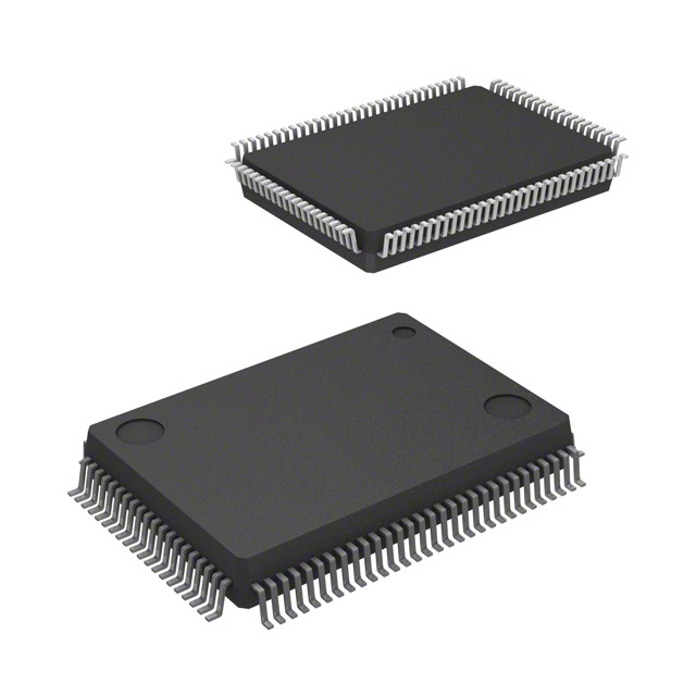


 工商网监
湘ICP备2023018690号
工商网监
湘ICP备2023018690号
