1428MHz Dual Output LVPECL
Clock Synthesizer
Product Discontinuance Notice – Last Time Buy Expires on (1/31/2014)
The MPC92433 is a 3.3 V compatible, PLL based clock synthesizer targeted for high
performance clock generation in mid-range to high-performance telecom, networking, and
computing applications. With output frequencies from 42.50 MHz to 1428 MHz and the
support of two differential PECL output signals, the device meets the needs of the most
demanding clock applications.
MPC92433
DATASHEET
1428 MHz LOW VOLTAGE
CLOCK SYNTHESIZER
Features
•
•
•
•
•
•
•
•
•
•
•
•
•
•
42.50 MHz to 1428 MHz synthesized clock output signal
Two differential, LVPECL-compatible high-frequency outputs
Output frequency programmable through 2-wire I2C bus or parallel interface
On-chip crystal oscillator for reference frequency generation
Alternative LVCMOS compatible reference clock input
Synchronous clock stop functionality for both outputs
LOCK indicator output (LVCMOS)
LVCMOS compatible control inputs
Fully integrated PLL
3.3 V power supply
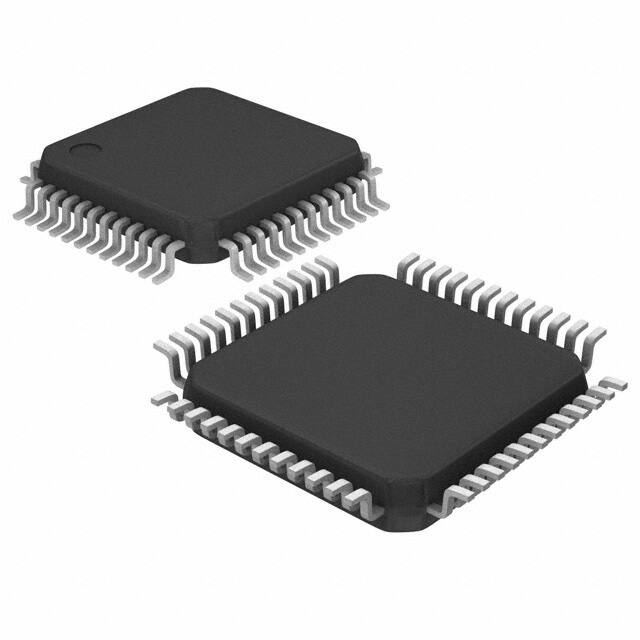
48-lead LQFP
48-lead Pb-free package available
SiGe Technology
Ambient temperature range: –40°C to +85°C
FA SUFFIX(1)
48-LEAD LQFP PACKAGE
CASE 932-03
AE SUFFIX(2)
48-LEAD LQFP PACKAGE
Pb-FREE PACKAGE
CASE 932-03
Typical Applications
•
•
•
Programmable clock source for server, computing, and telecommunication systems
Frequency margining
Oscillator replacement
The MPC92433 is a programmable high-frequency clock source (clock synthesizer). The internal PLL generates a high-frequency
output signal based on a low-frequency reference signal. The frequency of the output signal is programmable and can be changed on the
fly for frequency margining purposes.
The internal crystal oscillator uses the external quartz crystal as the basis of its frequency reference. Alternatively, a LVCMOS
compatible clock signal can be used as a PLL reference signal. The frequency of the internal crystal oscillator is divided by a selectable
divider and then multiplied by the PLL. The VCO within the PLL operates over a range of 1360 to 2856 MHz. Its output is scaled by a
divider that is configured by either the I2C or parallel interfaces. The crystal oscillator frequency fXTAL, the PLL pre-divider P, the feedbackdivider M, and the PLL post-divider N determine the output frequency. The feedback path of the PLL is internal.
The PLL post-divider N is configured through either the I2C or the parallel interfaces, and can provide one of seven division ratios (2,
4, 6, 8, 12, 16, 32). This divider extends the performance of the part while providing a 50 duty cycle. The high-frequency outputs, QA
and QB, are differential and are capable of driving a pair of transmission lines terminated 50 to
VCC – 2.0 V. The second high-frequency output, QB, can be configured to run at either 1x or 1/2x of the clock frequency or the first output
(QA). The positive supply voltage for the internal PLL is separated from the power supply for the core logic and output drivers to minimize
noise induced jitter.
The configuration logic has two sections: I2C and parallel. The parallel interface uses the values at the M[9:0], NA[2:0], NB, and P
parallel inputs to configure the internal PLL dividers. The parallel programming interface has priority over the serial I2C interface. The
serial interface is I2C compatible and provides read and write access to the internal PLL configuration registers. The lock state of the PLL
is indicated by the LVCMOS-compatible LOCK output.
1. FA suffix: leaded terminations.
2. AE suffix: lead-free, EPP and RoHS-compliant.
MPC92433 REVISION 3 FEBRUARY 6, 2013
1
©2013 Integrated Device Technology, Inc.
�MPC92433 Data Sheet
1428MHZ DUAL OUTPUT LVPECL CLOCK SYNTHESIZER
REF_CLK
XTAL1
fREF
XTAL
XTAL2
PLL
÷P
fQA
÷NA
fVCO
QA
fQB
÷NB
QB
REF_SEL
÷M
TEST_EN
SDA
ADR[1:0]
PLL
Configuration
Registers
PLOAD
I2C Control
SCL
LOCK
M[9:0]
NA[2:0]
NB
P
CLK_STOPx
BYPASS
MR
VCC
NB
VCC
QA
QA
GND
VCC
QB
QB
GND
LOCK
TEST_EN
Figure 1. MPC92433–Generic Logic Diagram
36
35
34
33
32
31
30
29
28
27
26
25
GND
37
24
M9
NA2
38
23
M8
39
22
M7
40
21
M6
PLOAD
41
20
M5
VCC
42
19
GND
MR
43
18
M4
SDA
44
17
M3
SCL
45
16
M2
ADR1
46
15
M1
ADR0
47
14
M0
P
48
13
VCC
MPC92433
11
12
XTAL2
10
XTAL1
9
CLK_STOPB
8
CLK_STOPA
7
GND
6
REF_CLK
5
REF_SEL
4
VCC_PLL
3
VCC
2
GND
1
VCC
NA0
BYPASS
NA1
It is recommended to use an external
RC filter for the analog VCC_PLL supply
pin. Please see the application section
for details.
Figure 2. 48-Lead Package Pinout (Top View)
MPC92433 REVISION 3 FEBRUARY 6, 2013
2
©2013 Integrated Device Technology, Inc.
�MPC92433 Data Sheet
1428MHZ DUAL OUTPUT LVPECL CLOCK SYNTHESIZER
Table 1. Signal Configuration
Pin
I/O
Type
Function
XTAL1, XTAL2
Input
Analog
Crystal oscillator interface
REF_CLK
Input
LVCMOS
PLL external reference input
REF_SEL
Input
LVCMOS
Selects the reference clock input
QA
Output
Differential LVPECL
High frequency clock output
QB
Output
Differential LVPECL
High frequency clock output
LOCK
Output
LVCMOS
PLL lock indicator
M[9:0]
Input
LVCMOS
PLL feedback divider configuration
NA[2:0]
Input
LVCMOS
PLL post-divider configuration for output QA
NB
Input
LVCMOS
PLL post-divider configuration for output QB
P
Input
LVCMOS
PLL pre-divider configuration
P_LOAD
Input
LVCMOS
Selects the programming interface
SDA
I/O
LVCMOS
I2C data
SCL
Input
LVCMOS
I2C clock
ADR[1:0]
Input
LVCMOS
Selectable two bits of the I2C slave address
BYPASS
Input
LVCMOS
Selects the static circuit bypass mode
TEST_EN
Input
LVCMOS
Factory test mode enable. This input must be set to logic low level in all
applications of the device.
CLK_STOPx
Input
LVCMOS
Output Qx disable in logic low state
MR
Input
LVCMOS
Device master reset
GND
Supply
Ground
Negative power supply
VCC_PLL
Supply
VCC
Positive power supply for the PLL (analog power supply). It is recommended
to use an external RC filter for the analog power supply pin VCC_PLL.
VCC
Supply
VCC
Positive power supply for I/O and core
MPC92433 REVISION 3 FEBRUARY 6, 2013
3
©2013 Integrated Device Technology, Inc.
�MPC92433 Data Sheet
1428MHZ DUAL OUTPUT LVPECL CLOCK SYNTHESIZER
Table 2. Function Table
Control
Default(1)
0
1
Inputs
REF_SEL
1
Selects REF_CLK input as PLL reference clock
Selects the XTAL interface as PLL reference
clock
M[9:0]
01 1111 0100b(2)
PLL feedback divider (10-bit) parallel programming interface
NA[2:0]
010
PLL post-divider parallel programming interface. See Table 9
NB
0
PLL post-divider parallel programming interface. See Table 9
P
1
PLL pre-divider parallel programming interface. See Table 8
PLOAD
0
Selects the parallel programming interface. The
internal PLL divider settings (M, NA, NB and P) are
equal to the setting of the hardware pins. Leaving the
M, NA, NB and P pins open (floating) results in a
default PLL configuration with fOUT = 250 MHz. See
application/programming section.
Selects the serial (I2C) programming interface.
The internal PLL divider settings (M, NA, NB and
P) are set and read through the serial interface.
ADR[1:0]
00
Address bit = 0
Address bit = 1
SDA, SCL
See Programming the MPC92433
BYPASS
1
PLL function bypassed
fQA=fREF÷ NA and
fQB=fREF÷ (NA· NB)
PLL function enabled
fQA = (fREF÷ P) · M ÷ NA and
fQB = (fREF ÷ P) · M ÷ (NA · NB)
TEST_EN
0
Application mode. Test mode disabled.
Factory test mode is enabled
CLK_STOPx
1
Output Qx is disabled in logic low state. Synchronous
disable is only guaranteed if NB = 0.
Output Qx is synchronously enabled
The device is reset. The output frequency is zero and
the outputs are asynchronously forced to logic low
state.
After releasing reset (upon the rising edge of MR and
independent on the state of PLOAD), the MPC92433
reads the parallel interface (M, NA, NB and P) to
acquire a valid startup frequency configuration. See
application/programming section.
The PLL attempts to lock to the reference signal.
The tLOCK specification applies.
PLL is not locked
PLL is frequency locked
MR
Outputs
LOCK
1. Default states are set by internal input pull-up or pull-down resistors of 75 k
2. If fREF = 16 MHz, the default configuration will result in an output frequency of 250 MHz.
MPC92433 REVISION 3 FEBRUARY 6, 2013
4
©2013 Integrated Device Technology, Inc.
�MPC92433 Data Sheet
1428MHZ DUAL OUTPUT LVPECL CLOCK SYNTHESIZER
Table 3. General Specifications
Symbol
Characteristics
Min
Typ
Max
Unit
VTT
Output Termination Voltage
MM
ESD Protection (Machine Model)
200
V
HBM
ESD Protection (Human Body Model)
2000
V
LU
Latch-Up Immunity
200
mA
CIN
Input Capacitance
JA
LQFP 48 Thermal Resistance Junction to Ambient
JESD 51-3, single layer test board
VCC – 2
JESD 51-6, 2S2P multilayer test board
JC
LQFP 48 Thermal Resistance Junction to Case
Condition
V
4.0
pF
Inputs
69
64
C/W
C/W
Natural convection
200 ft/min
53
50
C/W
C/W
Natural convection
200 ft/min
TBD
TBD
C/W
MIL-SPEC 883E
Method 1012.1
Min
Max
Unit
Condition
Table 4. Absolute Maximum Ratings(1)
Symbol
Characteristics
VCC
Supply Voltage
–0.3
3.9
V
VIN
DC Input Voltage(2)
–0.3
VCC + 0.3
V
VOUT
DC Output Voltage
–0.3
VCC + 0.3
V
DC Input Current
20
mA
DC Output Current
50
mA
125
C
IIN
IOUT
TS
Storage Temperature
–65
1. Absolute maximum continuous ratings are those maximum values beyond which damage to the device may occur. Exposure to these
conditions or conditions beyond those indicated may adversely affect device reliability. Functional operation at absolute-maximum-rated
conditions is not implied.
2. All input pins including SDA and SCL pins.
MPC92433 REVISION 3 FEBRUARY 6, 2013
5
©2013 Integrated Device Technology, Inc.
�MPC92433 Data Sheet
1428MHZ DUAL OUTPUT LVPECL CLOCK SYNTHESIZER
Table 5. DC Characteristics (VCC = 3.3 V ± 5%, TJ = –40°C to +85°C)
Symbol
Characteristics
Min
Typ
Max
Unit
Condition
LVCMOS Control Inputs (M[9:0], N[2:0], ADDR[1:0], NB, P, CLK_STOPx, BYPASS, MR, REF_SEL, TEST_EN, PLOAD)
VIH
Input High Voltage
2.0
—
VCC + 0.3
V
LVCMOS
VIL
Input Low Voltage
—
—
0.8
V
LVCMOS
IIN
Input Current(1)
—
—
±200
µA
VIN = VCC or GND
I2C Inputs (SCL, SDA)
VIH
Input High Voltage
2.0
—
VCC + 0.3
V
LVCMOS
VIL
Input Low Voltage
—
—
0.8
V
LVCMOS
IIN
Input Current
—
—
±10
µA
LVCMOS Output (LOCK)
VOH
Output High Voltage
2.4
—
—
V
IOH = –4 mA
VOL
Output Low Voltage
—
—
0.4
V
IOL = 4 mA
—
—
0.4
V
IOL = 4 mA
I2C Open-Drain Output (SDA)
VOL
Input Low Voltage
Differential Clock Output QA, QB(2)
VOH
Output High Voltage
VCC – 1.05
—
VCC – 0.74
V
LVPECL
VOL
Output Low Voltage
VCC – 1.95
—
VCC – 1.60
V
LVPECL
0.5
0.6
1.0
V
Maximum PLL Supply Current
—
—
10
mA
VCC_PLL Pins
Maximum Supply Current
—
—
150
mA
All VCC Pins
VO(P-P)
Output Peak-to-Peak Voltage
Supply current
ICC_PLL
ICC
1. Inputs have pull-down resistors affecting the input current.
2. Outputs terminated 50 to VTT = VCC – 2 V.
MPC92433 REVISION 3 FEBRUARY 6, 2013
6
©2013 Integrated Device Technology, Inc.
�MPC92433 Data Sheet
1428MHZ DUAL OUTPUT LVPECL CLOCK SYNTHESIZER
Table 6. AC Characteristics (VCC = 3.3 V ± 5%, TJ = –40°C to +85°C(1) (2)
Symbol
Characteristics
Min
Typ
Max
Unit
16
20
MHz
fXTAL
Crystal Interface Frequency Range
15
fREF
FREF_EXT Reference Frequency Range
15
20
MHz
fVCO
Range(3)
1360
2856
MHz
680
340
226.67
170
113.30
85
42.50
1428
714
476
357
238
178.50
89.25
MHz
MHz
MHz
MHz
MHz
MHz
MHz
0
0.4
MHz
VCO Frequency
Frequency(4)
fMAX
Output
fSCL
Serial Interface (I2C) Clock Frequency
tP,MIN
DC
tSK(O)
N= ÷2
N= ÷4
N= ÷6
N= ÷8
N= ÷12
N= ÷16
N= ÷32
Minimum Pulse Width
(P_LOAD)
50
Output Duty Cycle
45
Output-to-Output Skew
NB=0 (fQA = fQB)
NB=1 (fQA = 2· fQB)
tr, tf
Output Rise/Fall Time (QA, QB)
tr, tf
Output Rise/Fall Time (SDA)
0.05
Condition
ns
50
55
%
38
96
ps
ps
0.3
ns
20% to 80%
250
ns
CL = 400 pF
tP_EN
Output Enable Time (CLKSTOPx to QA, QB)
0
2 · TQx
TQx = Output period
tP_DIS
Output Disable Time (CLKSTOPx to QA, QB)
0
1.5 · TQx
TQx = Output period
(RMS)(5)
tJIT(CC)
Cycle-to-Cycle Jitter
tJIT(PER)
Period Jitter (RMS)(6)
NREF(UNLOCK)
tLOCK
N= ÷2, ÷4, ÷6, ÷8
N= ÷12
N= ÷16, ÷32
15
20
30
ps
ps
ps
N= ÷2
N= ÷4
N= ÷6
N= ÷8
N= ÷12
N= ÷16
N= ÷32
8
10
12
13
17
23
29
ps
ps
ps
ps
ps
ps
ps
10
ms
Number of missing reference clock cycles to
declare an out of LOCK condition(7)
2
Maximum PLL Lock Time
1. AC specifications are subject to change.
2. AC characteristics apply for parallel output termination of 50 to VTT.
3. The input frequency fXTAL, the PLL divider M and P must match the VCO frequency range: fVCO = fXTAL · M ÷ P. The feedback divider M is
limited to 170


 工商网监
湘ICP备2023018690号
工商网监
湘ICP备2023018690号
