ib technology
Data Sheet
OEM-MIFARE-ICODE.PDF
7 Pages
Last Revised 27/01/09
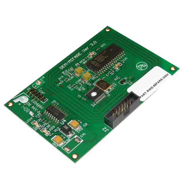
OEM-MIFARE-ICODE Reader Board
The OEM-MIFARE-ICODE Reader Board is a complete Read/Write system for ISO14443A
Mifare 1k, 4k, Ultralight and ISO15693 ICODE / TAG-IT cards and tags. It has an integrated
PCB track antenna, LEDs, TTL serial and I/O interface and is available in two versions; with
RS232 connector or USB (RS232 interface version requires 5 volt supply, USB version uses USB
bus for power supply).
The OEM boards are based on the proven RWD-MIFARE-ICODE module design with
components laid out inside a PCB track antenna and they function in exactly the same way as the
module with an antenna fitted. The design incorporates power supply filtering to ensure optimum
performance, antenna-trimming capacitor to adjust tuning for different environments and LEDs
for visual indication of card acceptance. The J2 connector also allows the OEM-MIFAREICODE board to be reprogrammed with custom firmware.
• Complete “plug-and-go” RFID Read / Write
system based on proven design.
OEM-MIFARE-ICODE-RS232
• Integrated PCB antenna, LEDS, RS232 or
USB interface.
• Supports Mifare 1k, 4k, Ultralight and ICODE
/ Tag-it (including contactless read/write to
Mifare ProX, SmartMX / JCOP cards).
OEM-MIFARE-ICODE-USB
• Average current consumption down to
100µ
µA (micro Amps) even when fully active.
• Auxiliary output options for automatic data
output as serial or Weigand protocol.
• “Reference Design Pack” available for ultra
low-cost higher volume applications.
This document should be read in conjunction with the MFPROT and MF_ICPROT data sheets
that detail the operation and command protocol for the RWD-MIFARE-ICODE modules (and
therefore OEM boards also). Because they use the same design and firmware as the RWD module
(and the Universal RFID base board) the Mifare Windows applications and RS232 HEX COM
utility can be used in the usual manner.
1
�ib technology
A “Reference Design Pack” is also available for customers who want to copy the board layout on
their own PCB and then just purchase the pre-programmed microcontroller from IB Technology.
For higher volume applications this “Reference Design” chipset solution will achieve a proven,
quick time-to-market embedded Reader product at the lowest possible cost and with minimum
effort.
OEM-MIFARE-ICODE-RS232
Mounting holes,
2 mm diameter
(for M2 screws)
1
J1
45 mm and 70 mm
between centres.
50 mm
J2
1
1
75 mm
OEM-MIFARE-ICODE-RS232 connectors (note Pin 1 positions on diagram),
note same J2 connector and pin out as USB version.
J2 connector: 2 x 6 way, TOBY boxed IDC header, 2mm pitch (www.toby.co.uk, C05-12-AG1G), mates with TOBY A05-12 socket or equivalent.
Connector J2 provides all the power, communication and control signals of the RWD-MIFAREICODE module on a single connector.
PIN 1: GND
PIN 3: 5v (Vcc IN)
PIN 5: CTS (5v)
PIN 7: GND
PIN 9: RX (5v)
PIN 11: Reset (MCLR)
PIN 2: OP0
PIN 4: Red LED
PIN 6: OP1
PIN 8: Green LED
PIN 10 SW1
PIN 12: TX (5v)
2
�ib technology
J1 connector: 5 way, 2 mm pitch header.
Connector J1 is used to connect the OEM-MIFARE-ICODE board to an RS232 serial port (as on
a PC). Note that if J1 is connected to a standard 9-way D-type serial connector then pins 1, 4 and
6 must be joined on the D-type connector. 5-volt supply must be connected to J1 pin 2 as shown.
1
6
PIN 1:
PIN 2:
PIN 3:
PIN 4:
PIN 5:
Supply GND
5V (Vcc IN)
CTS (12v)
RX (12v)
TX (12v)
1, 4, 6 - joined
2 – Tx
3 – Rx
5 – GND
8 - CTS
TX
RX
CTS
GND
9
5
9 way DIN socket
- RS232 connector
Specifications:
Power Supply: 5 volts, average current consumption typically less than 50 mA. Power supply
capable of providing 200mA is recommended.
Communication: 9600 baud, 8 bits, 1 stop, no parity.
OEM-MIFARE-ICODE-USB
Mounting holes,
2 mm diameter
(for M2 screws)
J1
45 mm and 70 mm
between centres.
50 mm
J2
1
1
75 mm
3
�ib technology
OEM-MIFARE-ICODE-USB connectors (note Pin 1 positions on diagram),
note same J2 connector and pin out as RS232 version.
J2 connector: 2 x 6 way, TOBY boxed IDC header, 2mm pitch (www.toby.co.uk, C05-12-AG1G), mates with TOBY A05-12 socket or equivalent.
Connector J2 provides all the power, communication and control signals of the RWD-MIFAREICODE module on a single connector.
J2 CONNECTOR TYPE AND PIN OUT IDENTICAL TO RS232 OEM BOARD.
J1 connector: USB (type B) connector.
USB connector J1 is used to connect the OEM-MIFARE-ICODE board to a standard USB host
port on a PC, which also provides the 5-volt power supply via the USB bus. The FTDI VCP
(Virtual COM Port) driver must be installed on the PC. This can be downloaded from IB
Technology website or from FTDI website (preferred location for latest version):
(http://www.ftdichip.com/Drivers/CDM/CDM%202.04.06.exe).
This provides the CDC (Communication Device Class) interface on the PC and allows Windows
applications to communicate with the OEM board as if it was connected to a standard COM port.
PIN 1: 5-volts
PIN 2: DATAPIN 3: DATA+
PIN 4: Ground
Specifications:
Power Supply (supplied by USB interface): average current consumption typically less than 50
mA. Communication via CDC (Communication Device Class) VCP (Virtual COM Port)
provided by FTDI Windows driver (OEM board communication: 9600 baud, 8 bits, 1 stop, no
parity).
4
�ib technology
Configuration parameter list
The OEM-MIFARE-ICODE Reader has internal (non-volatile) configuration parameters. These
are byte values that define all the Reader operational features such as the polling rate and
Auxiliary output options etc.. They can be changed using the PROGRAM command (see
MFPROT data sheet for command protocol).
Byte 0: Tag Polling Rate (default 0x60 = 262 milliseconds)
0x00 = 4mS
0x10 = 8mS
0x20 = 16mS
0x30 = 32mS
0x40 = 65mS
0x50 = 131mS
0x60 = 262mS (default)
0x70 = 524mS
0x80 = 1 second
0x90 = 2 seconds
0xA0 = 4 seconds
0xB0 = 8 seconds
Byte 1: Auxiliary data output
0x00 = OFF (no output from OP0 / OP1)
0x01 = 24 (26) bit Weigand OP0 / OP1
0x02 = 32( 34) bit Weigand OP0 / OP1
0x03 = 9600 baud serial from OP0 (default)
Byte 2: Checksum Value (Reserved – do not change)
Byte 3: Mifare/ICODE option byte
0x00 = MIFARE mode (default)
0x01 = ICODE mode
Byte 4: Weigand parity option
0x00 = No parity (default)
0x01 = Even/Odd parity added
Byte 5: Auxiliary Block Read address on card
Mifare card block address 0 - 255), default = 0x01
Byte 6: Key number / type to access Auxiliary data
(TxxKKKKK), (T = Key type, 0 = KeyA, 1 = KeyB)
(K = Key code number, 0 - 31)
default = 0x00, key 0, TypeA
Byte 7: "Beep" delay parameter (default 0x00 = OFF)
Beep delay = value x 40mS, 0x18 (24 decimal) = 1 second.
5
�ib technology
Byte 8: Auxiliary output base data selection.
0x00 = use UID/serial number (default)
0x01 = Perform Block Read)
Byte 9: Auxiliary output switch (redirects serial o/p)
0x00 = Aux output from OP0 pin (default)
0x01 = Aux output from Tx pin
Byte 10: Auxiliary output serial format, Hex or ASCII
0x00 = HEX format (default)
0x01 = ASCII character format
Byte 11: Auxiliary byte order option
0x00 = Plain data as read from card (default)
0x01 = Byte order Reversed
Byte 12 – Byte 255 forms the UID/serial number authorisation list. Groups of 4-byte serial
number can be stored here for authorisation. Default condition is Byte 12 – Byte 15 = 0xFF 0xFF
0xFF 0xFF indicating the list is empty (not used).
Byte 12: 0xFF
0xFF
0xFF
0xFF
Byte 16: 0xFF
0xFF
0xFF
0xFF
Byte 252: 0xFF
0xFF
0xFF
Byte 255: 0xFF
Empty list code
(LSB)
Empty list code
(LSB)
Empty list code
(LSB)
6
�ib technology
Mifare KEYCODE list
The OEM-MIFARE-ICODE Reader has additional internal (non-volatile) memory for storing up
to 32 Mifare KEYCODES. These are 6-byte “passwords” used for accessing the read/write
memory on Mifare cards. They can be changed using the STORE KEY command (see
MFPROT data sheet for command protocol). Default values are the Philips/NXP defined default
values (Transport keys) for new Mifare cards.
Location 0 (0x00):
Location 1 (0x01):
Key code 0 (Default 0xFF FF FF FF FF FF)
Key code 1 (Default 0xFF FF FF FF FF FF)
Location 2 (0x02):
Location 3 (0x03):
Location 28 (0x1C):
Location 29 (0x1D):
Key code 2 (Default 0xA0 A1 A2 A3 A4 A5)
Key code 3 (Default 0xB0 B1 B2 B3 B4 B5)
Key code 28 (Default 0xFF FF FF FF FF FF)
Key code 29 (Default 0xFF FF FF FF FF FF)
Location 30 (0x1E): Key code 30 (Default 0xA0 A1 A2 A3 A4 A5)
Location 31 (0x1F): Key code 31 (Default 0xB0 B1 B2 B3 B4 B5)
Please note that if different OEM board sizes or custom features are required then the “Reference
Design Pack” can be used and IB Technology can provide modified firmware to the customers
specification. Please contact support@ibtechnology.co.uk for further details.
More information on the Micro RWD and other products can be found at the Internet web site:
http://www.ibtechnology.co.uk
Or alternatively contact IB Technology by email at:
sales@ibtechnology.co.uk
7
�