®
RT4532
High Efficiency Backlight LED Driver
General Description
Features
The RT4532 is a high-efficiency LED driver for backlight
applications. An asynchronous boost converter with an
internal Schottky diode and a current source driver are
designed to support 6LED/channel with wide input voltage
range from 2.5V to 5.5V.
Input Voltage Range : 2.5V to 5.5V
An I2C interface can provide easy backlight control in fast
Internal Schottky Diode
Fast-speed mode I2C Compatible Interface
Drive Up to 6 WLEDs in 4 String
External PWM Brightness Control
550k/1.1MHz Switching Frequency
Built-in Internal Soft-Start
I 2 C Programmable 256 Steps Linear Current
Regulation
Up to 85% Efficiency with Small Magnetics
Programmable 16V/24V OVP
Current Accuracy ±5% and Current Balance ±3%
UVLO, OVP, OCP, OTP Protection
Shutdown Current : < 1μ
μA
Temperature Range : −40°°C to 85°°C
and high speed mode. The RT4532 supports linear
mappings with 256 steps to setup the brightness of
backlight LEDs. It also supports PWM dimming to adjust
the brightness.
The RT4532 provides complete protection functions such
as input under-voltage lockout, over-current, output overvoltage and over-temperature protection. The OVP
threshold voltage can be set at 16V and 24V for different
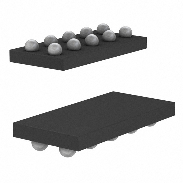
applications. The RT4532 is available in the
WL-CSP-10B 0.87x2.07 package.
Applications
Ordering Information
RT4532
Package Type
WSC : WL-CSP-10B 0.87x2.07 (BSC)
Cellular Phones
Digital Cameras
PDAs and Smart Phones
Portable Instruments
Note :
Richtek products are :
RoHS compliant and compatible with the current requirements of IPC/JEDEC J-STD-020.
Suitable for use in SnPb or Pb-free soldering processes.
Simplified Application Circuit
RT4532
L
LX
VOUT
COUT
VIN
VOUT
VIN
……
……
EN
……
Enable
……
CIN
x6
PWM
SCL
SDA
GND
Copyright © 2015 Richtek Technology Corporation. All rights reserved.
DS4532-01 August 2015
FB1
FB2
is a registered trademark of Richtek Technology Corporation.
www.richtek.com
1
�RT4532
Marking Information
Pin Configuration
(TOP VIEW)
2K : Product Code
2KW
LX
A1
A2
GND
VOUT
B1
B2
VIN
PWM
C1
C2
EN
SDA
D1
D2
SCL
FB2
E1
E2
FB1
W : Date Code
WL-CSP-10B 0.87x2.07(BSC)
Functional Pin Description
Pin No.
Pin Name
Pin Function
A1
LX
Switch node of boost converter. Connect an inductor between LX and VIN.
A2
GND
Ground.
B1
VOUT
Power output of the asynchronous boost converter for backlight LEDs. Connect a
1F or larger ceramic capacitor from VOUT to ground.
B2
VIN
Power input. Connect this pin to the input power supply voltage. Connect a 10F
or larger ceramic capacitor from the VIN to ground.
C1
PWM
PWM dimming input for backlight LED.
C2
EN
Enable control input (active high). The chip is in shutdown mode when the EN pin
is low.
D1
SDA
I2C serial data input/output. An external pull-up resistor is required.
D2
SCL
I2C serial clock input. An external pull-up resistor is required.
E1
FB2
Single output 2 for backlight LED.
E2
FB1
Single output 1 for backlight LED.
Copyright © 2015 Richtek Technology Corporation. All rights reserved.
www.richtek.com
2
is a registered trademark of Richtek Technology Corporation.
DS4532-01 August 2015
�RT4532
Functional Block Diagram
VIN
PWM
FB1
Current
Source Gen.
PWM2DC
VREF
SDA
EN
Digital
Control
LEDs
OTP
VFB
EA
SCL
LX
FB2
OVP
VOUT
+
-
PWM
Logic
VSLOPE
OCP
GND
Operation
The RT4532 is a high efficiency solution with 24 WLEDs
in 4 parallels 6 series for backlight applications. The
RT4532 optimizes the feedback regulation voltage to
provide up to 85% high efficiency with as high as 8bits
resolution application.
OCP Protection
The RT4532 features a 1.2A current limitation. Once
detecting current level over current limitation, the RT4532's
LX witching will be forced off to avoid large current damage.
OTP Protection
Linear Brightness Dimming
The RT4532 is built-in a I2C 8-bit resolution brightness
control with maximum 20mA/40mA selection.
Reg0x02 corresponds to full-scale LED current control.
Reg0x04 sets 8bits resolution brightness dimming.
The over-temperature protection function will be latched
at shutdown status when the junction temperature
exceeds 140°C for 2ms. After re-power on sequence, the
converter will automatically resume switching.
OVP Protection
PWM Brightness Dimming
Besides programmable built-in I2C backlight LED current
control, the RT4532 features a built-in PWM dimming
current control by setting Reg0x02 to 1, offering a
linear current dimming by external clock source. In order
to guarantee the PWM dimming resolution, recommending
dimming frequency have to be operated at range of 400Hz
to 20kHz.
Copyright © 2015 Richtek Technology Corporation. All rights reserved.
DS4532-01 August 2015
The over-voltage protection function monitors the output
voltage via the VOUT pin voltage. The OVP threshold
voltage is 24V/16V by selecting Reg0x02. Once the
LED is open, the output voltage reaches the OVP
threshold, the driver will be shut down.
is a registered trademark of Richtek Technology Corporation.
www.richtek.com
3
�RT4532
Absolute Maximum Ratings
(Note 1)
Supply Input Voltage, VIN ----------------------------------------------------------------------------------------------Boost Output Voltage, VOUT ------------------------------------------------------------------------------------------Switching Voltage, LX ---------------------------------------------------------------------------------------------------Current Source Voltage, FB1, FB2 -----------------------------------------------------------------------------------Other Pins, EN, PWM, SCL, SDA -----------------------------------------------------------------------------------Power Dissipation, PD @ TA = 25°C
−0.3V to 6V
−0.3V to 26V
−0.3V to 26V
−0.3V to 26V
−0.3V to 6V
WL-CSP-10B 0.87x2.07 (BSC) ---------------------------------------------------------------------------------------Package Thermal Resistance (Note 2)
WL-CSP-10B 0.87x2.07 (BSC), θJA ---------------------------------------------------------------------------------Lead Temperature (Soldering, 10 sec.) ------------------------------------------------------------------------------Junction Temperature ----------------------------------------------------------------------------------------------------Storage Temperature Range -------------------------------------------------------------------------------------------ESD Susceptibility (Note 3)
HBM (Human Body Model) ---------------------------------------------------------------------------------------------MM (Machine Model) -----------------------------------------------------------------------------------------------------
1W
Recommended Operating Conditions
99.6°C/W
260°C
150°C
−65°C to 150°C
2kV
200V
(Note 4)
Supply Input Voltage, VIN ----------------------------------------------------------------------------------------------- 2.5V to 5.5V
Junction Temperature Range -------------------------------------------------------------------------------------------- −40°C to 125°C
Ambient Temperature Range -------------------------------------------------------------------------------------------- −40°C to 85°C
Electrical Characteristics
(VIN = 3.6V, CIN = 10μF, COUT = 1μF, L = 10μH, TA = 25°C, unless otherwise specified)
Parameter
Symbol
Test Conditions
Min
Typ
Max
Unit
2.5
--
5.5
V
Input Power Supply
Input Supply Voltage
VIN
VIN Quiescent Current
IQ
PWM, No Switching
--
0.6
--
mA
Shutdown Current
ISHDN
VIN = 4.2V, EN = GND
--
1
3
A
Under-Voltage Lockout
Threshold
VUVLO
VIN Falling, Check IQ < 200A
--
--
2.3
V
Under-Voltage Lockout
Hysteresis
VUVLO
After UVLO, VIN Rising,
Until IQ > 200µA
--
150
--
mV
Backlight LED Current Source
Accuracy of Output Current
ILED_ACC
FB1, FB2 = 0.15V, IFB1 = IFB2 = 20mA
5
--
5
%
Matching of Output Current
ILED_MAT
FB1, FB2 = 0.15V, IFB1 = IFB2 = 20mA
3
--
3
%
Operating Frequency
f SW
Reg0x03 [6] = 1
0.88
1.1
1.32
MHz
Maximum Duty Cycle
DMAX
FB1 = FB2 = 0V, check MAX duty
90
95
--
%
Brightness Ramp Rate
TRAMP
Reg0x03 [5:0] = 111111
Oscillator and Timing
Copyright © 2015 Richtek Technology Corporation. All rights reserved.
www.richtek.com
4
209.72 262.14 314.58
ms
is a registered trademark of Richtek Technology Corporation.
DS4532-01 August 2015
�RT4532
Parameter
Symbol
Test Conditions
Min
Typ
Max
Unit
100
200
300
m
1
1.2
1.4
A
LX = 24V, No Switching
--
--
1
A
Reg0x02 [7] = 0
14
16
18
V
Reg0x02 [7] = 1
23
24
25
V
Thermal latch
--
150
--
°C
Power Switch
N-MOSFET On-Resistance
RDS(ON)_N VIN = 3.6V
N-MOSFET Current Limit
IOCP
N-MOSFET Leakage
Current
ILEAK
Protection Function
Over Voltage Protection
Thermal Shutdown
Threshold
OVP
TSD
Logic Control
EN Input
Voltage
Logic-High
VENH
1.05
--
--
Logic-Low
VENL
--
--
0.4
PWM Input
Voltage
Logic-High
VPWML
1.05
--
--
Logic-Low
VPWML
--
--
0.4
SCL Input
Voltage
Logic-High
VSCLH
1.3
--
--
Logic-Low
VSCLL
--
--
0.4
SDA Input
Voltage
Logic-High
VSDAH
1.3
--
--
Logic-Low
VSDAL
--
--
0.4
EN Pull-Down Resistance
--
400
--
k
PWM Pull-Down Resistance
--
400
--
k
--
--
400
kHz
Clock Frequency of SCL
f SCL
V
V
V
V
Note 1. Stresses beyond those listed “Absolute Maximum Ratings” may cause permanent damage to the device. These are
stress ratings only, and functional operation of the device at these or any other conditions beyond those indicated in
the operational sections of the specifications is not implied. Exposure to absolute maximum rating conditions may
affect device reliability.
Note 2. θJA is measured at TA = 25°C on a high effective thermal conductivity four-layer test board per JEDEC 51-7. θJC is
measured at the exposed pad of the package.
Note 3. Devices are ESD sensitive. Handling precaution is recommended.
Note 4. The device is not guaranteed to function outside its operating conditions.
Copyright © 2015 Richtek Technology Corporation. All rights reserved.
DS4532-01 August 2015
is a registered trademark of Richtek Technology Corporation.
www.richtek.com
5
�RT4532
Typical Application Circuit
L
10µH
2
1
VIN
EN
PWM
4 SCL
5
SDA
8, 11 (Exposed Pad)
GND
……
3
COUT
1µF
……
Enable
VOUT 9
……
CIN
10µF
LX
……
VIN
2.5V to 5.5V
RT4532
10
VOUT
x6
FB1 7
FB2 6
Timing Diagram
Power Sequence
Reg0x04 = FF Reg0x04 = Reg0x02 = C7 Count 2^17
Clock
As Reg Default
00
PWM Enable
EN
Count 2^17
Clock
Reg0x02 = 0
DEV_EN Disable
Duty =50%
PWM
I(MAX)
I(MAX)/2
I(LED)
I(MIN)
0
0
Note : PWM prd : count by OSC : 17.6MegHz
> 1024 : Resolution = 7bits & < 1000 : Resolution = 8bits
Copyright © 2015 Richtek Technology Corporation. All rights reserved.
www.richtek.com
6
is a registered trademark of Richtek Technology Corporation.
DS4532-01 August 2015
�RT4532
Protection Timing
OTP
EN
sOTP
2ms
2ms
sEnbl
Reg0x05
record
Register
LED Short
EN
LED1_F or LED2_F Short
2ms
2ms
sEnbl
Reg0x05
record
Register
LED Open
EN
40 times
sOVP
… x 39 times
sEnbl
Register
Copyright © 2015 Richtek Technology Corporation. All rights reserved.
DS4532-01 August 2015
Reg0x05
record
is a registered trademark of Richtek Technology Corporation.
www.richtek.com
7
�RT4532
Table 1. Register Map
Slave Address = 0100010x
Address
Address
Name
0x00
Device ID
0x01
Manufacture
0x02
0x03
0x04
0x05
Config1
Timing
Linear
Brightness
Control
FLAG
BIT
LABEL
Description
7:0
DEV_ID
7:2
REV
000000
Revision number
1:0
VID
11
Vendor ID : Richtek
7
OVPsel
1
OVP threshold ([0] 16V, [1] 24V)
6
PWM_EN
1
PWM enable : [0] Ignored, [1] Enable
5
PWM _SET
0
PWM active setup : [0] High active, [1] Low
active
4
Reserved
3
MAX_Current
0
[0] 20mA, [1] 40mA,
2
LED1_EN
1
Backlight LED1 : [0] OFF, [1] ON
1
LED2_EN
1
Backlight LED2 : [0] OFF, [1] ON
0
DEV_EN
1
CHIP enable : [0] OFF, [1] ON
7
RST_SW
0
Software reset : [0] Disable(Auto), [1] Reset all
registers
6
FSW
1
Switching frequency ([0]550kHz, [1]1.1MHz)
000
Brightness ramp-up rate : [000] 32s, [001]
4.096ms, [010] 8.192ms, [011] 16.383ms, [100]
32.768ms, [101] 65.536ms, [110] 131.072ms,
[111] 262.144ms
5:3
UP_RATE
2:0
DN_RATE
000
Brightness ramp-down rate : [000] 32s, [001]
4.096ms, [010] 8.192ms, [011] 16.383ms, [100]
32.768ms, [101] 65.536ms, [110] 131.072ms,
[111] 262.144ms
7:0
BRIGHT_LIN
00000000
[00000000] 0.39%, [00000001] 0.39%,
……
[111111111] 100%
7:4
Reserved
0
3
LED1_FT
0
LED1 short : [0] Normal, [1] Fault
2
LED2_FT
0
LED2 short : [0] Normal, [1] Fault
1
OVP
0
Output over voltage : [0] Normal, [1] Fault
0
OTP
0
Over temperature : [0] Normal, [1] Fault
Copyright © 2015 Richtek Technology Corporation. All rights reserved.
www.richtek.com
8
Default
(Reset Value)
is a registered trademark of Richtek Technology Corporation.
DS4532-01 August 2015
�RT4532
Typical Operating Characteristics
Efficiency vs. Linear Brightness Control
Efficiency vs. Input Voltage
100
100
90
90
80
Efficiency (%)
Efficiency (%)
80
70
60
50
70
60
50
40
30
20
40
10
CIN = 10μF, COUT = 1μF, L = 10μH
CIN = 10μF, COUT = 1μF, L = 10μH, ILED = 20mA
0
30
0
25
50
2.5
75 100 125 150 175 200 225 250 275
3
PWM Dimming Operation
5
5.5
Switching Frequency vs. Input Voltage
Switching Frequency (MHz)1
40
LED Current (mA)
4.5
1.15
45
35
ILED = 40mA
30
25
ILED = 20mA
20
15
10
5
0
20
40
60
80
1.12
1.09
1.06
1.03
CIN = 10μF, COUT = 1μF, L = 10μH
VIN = 3.6V
1.00
0
2.5
100
3
Dimming Duty (%)
3.5
4
4.5
5
5.5
Input Voltage (V)
Quiescent Current vs. Input Voltage
Shutdown Current vs. Input Voltage
0.45
Non-Switching
0.40
1200
Shutdown Current (μA)1
Quiescent Current (μA)
4
Input Voltage (V)
Linear Brightness Control (Step)
1400
3.5
1000
800
600
400
200
0.35
0.30
0.25
0.20
0.15
0.10
0.05
0.00
0
2.5
3
3.5
4
4.5
5
Input Voltage (V)
Copyright © 2015 Richtek Technology Corporation. All rights reserved.
DS4532-01 August 2015
5.5
2.5
3
3.5
4
4.5
5
5.5
Input Voltage (V)
is a registered trademark of Richtek Technology Corporation.
www.richtek.com
9
�RT4532
Application Information
LED Short Protection
LED short protection prevents abnormal connection to
cause IC damage avoiding FB1/FB2 connecting power
supply. And, If unbalanced LEDs series (cause FB1 or
FB2 > 9.6V) is different between channel1 and channel2,
IC will also occur LED short event. As LED short event
occur more than deglitch time 2ms, IC will shut-down latch
until IC is reset by EN pin.
Soft-Start
The RT4532 includes a soft-start function to avoid high
inrush current during start-up. The soft-start function is
achieved by clamping the output voltage of the error
amplifier with another voltage source that is increased
slowly from zero to near VIN during the soft-start period.
threshold, the device is shut down. If the input voltage
rises by under-voltage lockout hysteresis (200mV typical),
the IC restarts.
Linear Brightness Dimming
The chip is built-in an I2C 8-bit resolution brightness control
with maximum 20mA/40mA selection. Reg0x02
corresponds to full-scale LED current control. Reg0x04
sets 8bits resolution brightness dimming control.
ILED =
Code
ILED, Full
255
Where
ILED, Full : the full-scale LED current set by Reg0x02 .
Code : the 8bit brightness code Reg0x04
programmed by I2C interface.
OCP Protection
The RT4532 features a 1A current limitation. The current
flowing through the inductor during a charging period is
detected by a current sensing circuit. If the value exceeds
the current limit, the N-MOSFET will be turned off. The
inductor will then be forced to leave charging stage and
enter discharging stage. Therefore, the inductor current
will not increase to reach current limit.
The over-temperature protection function will be latched
at shutdown status when the junction temperature
exceeds 140°C for 2ms. After re-power on sequence, the
converter will automatically resume switching.
OVP Protection
The chip provides over-voltage protection function to limit
the output voltage in abnormal conditions. The OVP
threshold voltage is 24V/16V by selecting Reg0x02 .
Once the LED is open, the output voltage reaches the
OVP threshold, the driver will be shut down.
Under-Voltage Lockout
An under-voltage lockout circuit prevents the operation of
the device at input voltages below under-voltage threshold
(2.3V maximum). When the input voltage is below the
Copyright © 2015 Richtek Technology Corporation. All rights reserved.
www.richtek.com
10
PWM Brightness Dimming
Besides programmable built-in I2C backlight LED current
control, the RT4532 features a built-in PWM dimming
current control by setting Reg0x02 to 1, offering a
linear current dimming by external clock source. In order
to guarantee the PWM dimming resolution (7 bit at >
15kHz application), recommending dimming frequency
have to be operated at range of 400Hz to 20kHz.
Inductor Selection
The recommended inductor value for dual-channel 6
WLEDs applications is 10μH. When selecting the
inductor, the inductor rated saturation current should be
higher than the peak current at maximum load. Small size
and better efficiency are major concerns for portable
devices. The inductor should have low core loss at 1.1MHz
and low DCR for better efficiency.
Capacitor Selection
10μF input ceramic capacitor and 1μF output ceramic
capacitor are recommended for driving dual-channel 6
WLEDs applications. For better voltage filtering, ceramic
capacitors with low ESR are recommended. X5R and X7R
types are suitable because of their wide voltage and
temperature ranges.
is a registered trademark of Richtek Technology Corporation.
DS4532-01 August 2015
�RT4532
Thermal Considerations
Layout Consideration
For continuous operation, do not exceed absolute
maximum junction temperature. The maximum power
dissipation depends on the thermal resistance of the IC
package, PCB layout, rate of surrounding airflow, and
difference between junction and ambient temperature. The
maximum power dissipation can be calculated by the
following formula :
As for all switching power supplies, the layout is an
important step in the design, especially at high peak
currents and switching frequencies. If the layout is not
carefully done, the regulator might expose noise problems
and duty cycle jitter. Therefore, use wide and short traces
for high current paths. The input capacitor should be placed
as close as possible to the input pin for good input voltage
filtering. The inductor should be placed as close as possible
to the switch pin to minimize the noise coupling into other
circuits. The output capacitor needs to be placed directly
from the VOUT pin to GND rather than across the LEDs.
This reduces the ripple current in the trace to the LEDs.
When doing the PCB layout, the bold traces should be
routed first, as well as placement of the inductor, and input
and output capacitors.
PD(MAX) = (TJ(MAX) − TA) / θJA
where TJ(MAX) is the maximum junction temperature, TA is
the ambient temperature, and θJA is the junction to ambient
thermal resistance.
For recommended operating condition specifications, the
maximum junction temperature is 125°C. The junction to
ambient thermal resistance, θJA, is layout dependent. For
WL-CSP-10B 0.87x2.07 (BSC) package, the thermal
resistance, θJA, is 99.6°C/W on a standard JEDEC 51-7
four-layer thermal test board. The maximum power
dissipation at TA = 25°C can be calculated by the following
formula :
P D(MAX) = (125°C − 25°C) / (99.6°C/W) = 1W for
WL-CSP-10B 0.87x2.07 (BSC) package
The maximum power dissipation depends on the operating
ambient temperature for fixed T J(MAX) and thermal
resistance, θJA. The derating curve in Figure 1 allows the
designer to see the effect of rising ambient temperature
on the maximum power dissipation.
Maximum Power Dissipation (W)1
1.2
Four-Layer PCB
1.0
0.8
0.6
0.4
0.2
0.0
0
25
50
75
100
125
Ambient Temperature (°C)
Figure 1. Derating Curve of Maximum Power Dissipation
Copyright © 2015 Richtek Technology Corporation. All rights reserved.
DS4532-01 August 2015
is a registered trademark of Richtek Technology Corporation.
www.richtek.com
11
�RT4532
Outline Dimension
Symbol
Dimensions In Millimeters
Dimensions In Inches
Min
Max
Min
Max.
A
0.500
0.600
0.020
0.024
A1
0.170
0.230
0.007
0.009
b
0.240
0.300
0.009
0.012
D
2.020
2.120
0.080
0.083
D1
E
1.600
0.820
0.063
0.920
0.032
0.036
E1
0.400
0.016
e
0.400
0.016
10B WL-CSP 0.87x2.07 Package (BSC)
Richtek Technology Corporation
14F, No. 8, Tai Yuen 1st Street, Chupei City
Hsinchu, Taiwan, R.O.C.
Tel: (8863)5526789
Richtek products are sold by description only. Richtek reserves the right to change the circuitry and/or specifications without notice at any time. Customers should
obtain the latest relevant information and data sheets before placing orders and should verify that such information is current and complete. Richtek cannot
assume responsibility for use of any circuitry other than circuitry entirely embodied in a Richtek product. Information furnished by Richtek is believed to be
accurate and reliable. However, no responsibility is assumed by Richtek or its subsidiaries for its use; nor for any infringements of patents or other rights of third
parties which may result from its use. No license is granted by implication or otherwise under any patent or patent rights of Richtek or its subsidiaries.
www.richtek.com
12
DS4532-01 August 2015
�


 工商网监
湘ICP备2023018690号
工商网监
湘ICP备2023018690号