®
RT6259A/B
3A, 18V, 650kHz, ACOTTM Synchronous Step-Down Converter
General Description
The RT6259A/B are high-performance 650kHz 3A stepdown regulators with internal power switches and
synchronous rectifiers. They feature quick transient
response using their Advanced Constant On-Time
(ACOT TM) control architecture that provides stable
operation with small ceramic output capacitors and without
complicated external compensation, among other benefits.
The input voltage range is from 4.5V to 18V and the output
is adjustable from 0.765V to 7V.
to avoid low-frequency interference while the RT6259A
features a power-saving discontinuous operating mode at
light loads.
Features
TM
The proprietary ACOT control improves upon other fastresponse constant on-time architectures, achieving nearly
constant switching frequency over line, load, and output
voltage ranges. Since there is no internal clock, response
to transients is nearly instantaneous and inductor current
can ramp quickly to maintain output regulation without
large bulk output capacitance. The RT6259A/B are stable
with and optimized for ceramic output capacitors.
With internal 70mΩ switches and 70mΩ synchronous
rectifiers, the RT6259A/B display excellent efficiency and
good behavior across a range of applications, especially
for low output voltages and low duty cycles. Cycle-bycycle current limit, input under-voltage lockout, externallyadjustable soft-start, output under- and over-voltage
protection, and thermal shutdown provide safe and smooth
operation in all operating conditions.
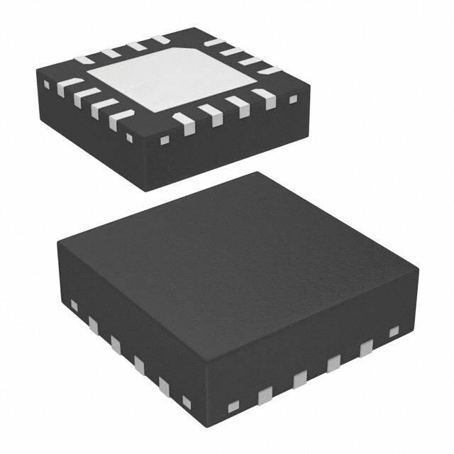
The RT6259A and RT6259B are each available in
the WQFN-16L 3x3 package, with exposed thermal pads.
The RT6259B switches continuously even at light loads
Fast Transient Response
Steady 650kHz Switching Frequency At all Load
Current (RT6259B)
Discontinuous Operating Mode at Light Load
(RT6259A)
3A Output Current
Advanced Constant On-Time (ACOTTM) Control
Optimized for Ceramic Output Capacitors
4.5V to 18V Input Voltage Range
Internal 70mΩ
Ω Switch and 70mΩ
Ω Synchronous
Rectifier
0.765V to 7V Adjustable Output Voltage
Externally-adjustable, Pre-biased Compatible SoftStart
Cycle-by-Cycle Current Limit
Optional Output Discharge Function
Output Over- and Under-voltage Shut Down
Latched (RT6259ALGQW/RT6259BLGQW Only)
With Hiccup Mode (RT6259AHGQW/RT6259BHGQW
Only)
Input Under-Voltage Lockout
Thermal Shutdown
RoHS Compliant and Halogen Free
Simplified Application Circuit
VIN
RT6259A/B
VIN
SW
VCC
Power Good
VREG5
Input Signal
PGOOD
September 2015
BOOT
VS
FB
EN
SS
VREG5
GND PGND
Copyright © 2015 Richtek Technology Corporation. All rights reserved.
DS6259A/B-01
VOUT
is a registered trademark of Richtek Technology Corporation.
www.richtek.com
1
�RT6259A/B
Applications
Industrial and Commercial Low Power Systems
Computer Peripherals
LCD Monitors and TVs
Green Electronics/Appliances
Point of Load Regulation for High-Performance DSPs,
FPGAs, and ASICs
Ordering Information
RT6259A/B
Package Type
QW : WQFN-16L 3x3 (W-Type)
Lead Plating System
G : Green (Halogen Free and Pb Free)
H : Hiccup Mode OVP & UVP
L : Latched OVP & UVP
A : PSM
B : PWM
Marking Information
RT6259AHGQW
6R= : Product Code
6R=YM
DNN
YMDNN : Date Code
Note :
Richtek products are :
RoHS compliant and compatible with the current requirements of IPC/JEDEC J-STD-020.
Suitable for use in SnPb or Pb-free soldering processes.
RT6259ALGQW
6Q= : Product Code
YMDNN : Date Code
Pin Configurations
(TOP VIEW)
VS
VCC
VIN
VIN
6Q=YM
DNN
16 15 14 13
RT6259BHGQW
6P= : Product Code
6N= : Product Code
GND
3
10
17
4
6
7
9
BOOT
SW
SW
SW
8
WQFN-16L 3x3
YMDNN : Date Code
Copyright © 2015 Richtek Technology Corporation. All rights reserved.
www.richtek.com
2
11
5
RT6259BLGQW
6N=YM
DNN
12
2
PGOOD
EN
PGND
PGND
6P=YM
DNN
YMDNN : Date Code
FB
VREG5
SS
GND
1
is a registered trademark of Richtek Technology Corporation.
DS6259A/B-01
September 2015
�RT6259A/B
Functional Pin Description
Pin No.
Pin Name
Pin Function
1
FB
Feedback Voltage Input. Connect FB to the midpoint of the external feedback
resistiv e divider to sense the output voltage. Place the resistive divider within
5mm from the FB pin. The IC regulates VFB at 0.765V (typical).
2
VREG5
Internal Regulator Output. Connect a 1F capacitor to GND to stabilize
output voltage.
3
SS
Soft-Start Control. Connect an external capacitor between this pin and GND
to set the soft-start time.
4
GND
Ground.
5
PGOOD
Open-Drain Power-good Output. PGOOD connects to PGND whenever VFB
is less than 90% of its regulation threshold (typical).
6
EN
Enable Control Input. A logic-high enables the converter; a logic-low forces
the IC into shutdown mode reducing the supply current to less than 10A.
PGND
Power Ground. PGND connects to the Source of the internal N-channel
MOSFET synchronous rectifier and to other power ground nodes of the IC.
The exposed pad and the 2 PGND pins should be well soldered to the input
and output capacitors and to a large PCB area for good power dissipation.
SW
Switch Node. SW is the Source of the internal N-channel MOSFET switch
and the Drain of the internal N-channel MOSFET synchronous rectifier.
Connect SW to the inductor with a wide short PCB trace and minimize its
area to reduce EMI.
BOOT
Bootstrap Supply for High-Side Gate Driver. Connect a 0.1F capacitor
between BOOT and SW to power the internal gate driver.
13, 14
VIN
Power Input. The input voltage range is from 4.5V to 18V. Must bypass with a
suitably large (10F x 2) ceramic capacitors at this pin.
15
VCC
Internal Linear Regulator Supply Input. VCC supplies power for the internal
linear regulator that powers the IC. Connect VIN to the input voltage and
bypass to ground with a 0.1F ceramic capacitor.
16
VS
Output Voltage Sense Input.
7, 8,
17 (Exposed pad)
9, 10, 11
12
Copyright © 2015 Richtek Technology Corporation. All rights reserved.
DS6259A/B-01
September 2015
is a registered trademark of Richtek Technology Corporation.
www.richtek.com
3
�RT6259A/B
Function Block Diagram
VCC VREG5
POR &
Reg
EN
VBIAS
BOOT
Min.
Off-Time
VREG5
2µA
SS
VIN
FB
VS
VIN
VREF
OC
UV & OV
VREG5
Control
Driver
SW
PGND
SW
ZC
Ripple
Gen.
FB
+
+
Comparator
GND
FB
0.9 x VREF
Comparator
+
PGOOD
On-Time
Detailed Description
The RT6259A/B are high-performance 650kHz 3A stepdown regulators with internal power switches and
synchronous rectifiers. They feature an Advanced Constant
On-Time (ACOTTM) control architecture that provides
stable operation with ceramic output capacitors without
complicated external compensation, among other benefits.
The input voltage range is from 4.5V to 18V and the output
is adjustable from 0.765V to 7V.
The proprietary ACOTTM control scheme improves upon
other constant on-time architectures, achieving nearly
constant switching frequency over line, load, and output
voltage ranges. The RT6259A/B are optimized for ceramic
output capacitors. Since there is no internal clock,
response to transients is nearly instantaneous and inductor
current can ramp quickly to maintain output regulation
without large bulk output capacitance.
Constant On-Time (COT) Control
The heart of any COT architecture is the on-time oneshot. Each on-time is a pre-determined “fixed” period
that is triggered by a feedback comparator. This robust
arrangement has high noise immunity and is ideal for low
Copyright © 2015 Richtek Technology Corporation. All rights reserved.
www.richtek.com
4
duty cycle applications. After the on-time one-shot period,
there is a minimum off-time period before any further
regulation decisions can be considered. This arrangement
avoids the need to make any decisions during the noisy
time periods just after switching events, when the
switching node (SW) rises or falls. Because there is no
fixed clock, the high-side switch can turn on almost
immediately after load transients and further switching
pulses can ramp the inductor current higher to meet load
requirements with minimal delays.
Traditional current mode or voltage mode control schemes
typically must monitor the feedback voltage, current
signals (also for current limit), and internal ramps and
compensation signals, to determine when to turn off the
high-side switch and turn on the synchronous rectifier.
Weighing these small signals in a switching environment
is difficult to do just after switching large currents, making
those architectures problematic at low duty cycles and in
less than ideal board layouts.
Because no switching decisions are made during noisy
time periods, COT architectures are preferable in low duty
cycle and noisy applications. However, traditional COT
is a registered trademark of Richtek Technology Corporation.
DS6259A/B-01
September 2015
�RT6259A/B
control schemes suffer from some disadvantages that
preclude their use in many cases. Many applications require
a known switching frequency range to avoid interference
with other sensitive circuitry. True constant on-time control,
where the on-time is actually fixed, exhibits variable
switching frequency. In a step-down converter, the duty
factor is proportional to the output voltage and inversely
proportional to the input voltage. Therefore, if the on-time
is fixed, the off-time (and therefore the frequency) must
change in response to changes in input or output voltage.
Modern pseudo-fixed frequency COT architectures greatly
improve COT by making the one-shot on-time proportional
to VOUT and inversely proportional to VIN. In this way, an
on-time is chosen as approximately what it would be for
an ideal fixed-frequency PWM in similar input/output
voltage conditions. The result is a big improvement but
the switching frequency still varies considerably over line
and load due to losses in the switches and inductor and
other parasitic effects.
Another problem with many COT architectures is their
dependence on adequate ESR in the output capacitor,
making it difficult to use highly-desirable, small, low-cost,
but low-ESR ceramic capacitors. Most COT architectures
use AC current information from the output capacitor,
generated by the inductor current passing through the
ESR, to function in a way like a current mode control
system. With ceramic capacitors, the inductor current
information is too small to keep the control loop stable,
like a current mode system with no current information.
ACOTTM Control Architecture
Making the on-time proportional to VOUT and inversely
proportional to VIN is not sufficient to achieve good
constant-frequency behavior for several reasons. First,
voltage drops across the MOSFET switches and inductor
cause the effective input voltage to be less than the
measured input voltage and the effective output voltage to
be greater than the measured output voltage. As the load
changes, the switch voltage drops change causing a
switching frequency variation with load current. Also, at
light loads if the inductor current goes negative, the switch
dead-time between the synchronous rectifier turn-off and
the high-side switch turn-on allows the switching node to
Copyright © 2015 Richtek Technology Corporation. All rights reserved.
DS6259A/B-01
September 2015
rise to the input voltage. This increases the effective ontime and causes the switching frequency to drop
noticeably.
One way to reduce these effects is to measure the actual
switching frequency and compare it to the desired range.
This has the added benefit eliminating the need to sense
the actual output voltage, potentially saving one pin
connection. ACOTTM uses this method, measuring the
actual switching frequency (at SW) and modifying the ontime with a feedback loop to keep the average switching
frequency in the desired range.
To achieve good stability with low-ESR ceramic capacitors,
ACOTTM uses a virtual inductor current ramp generated
inside the IC. This internal ramp signal replaces the ESR
ramp normally provided by the output capacitor's ESR.
The ramp signal and other internal compensations are
optimized for low-ESR ceramic output capacitors.
ACOTTM One-shot Operation
The RT6259A/B control algorithm is simple to understand.
The feedback voltage, with the virtual inductor current ramp
added, is compared to the reference voltage. When the
combined signal is less than the reference the on-time
one-shot is triggered, as long as the minimum off-time
one-shot is clear and the measured inductor current
(through the synchronous rectifier) is below the current
limit. The on-time one-shot turns on the high-side switch
and the inductor current ramps up linearly. After the ontime, the high-side switch is turned off and the synchronous
rectifier is turned on and the inductor current ramps down
linearly. At the same time, the minimum off-time one-shot
is triggered to prevent another immediate on-time during
the noisy switching time and allow the feedback voltage
and current sense signals to settle. The minimum off-time
is kept short (260ns typical) so that rapidly-repeated ontimes can raise the inductor current quickly when needed.
Discontinuous Operating Mode (RT6259A Only)
After soft-start, the RT6259B operates in fixed frequency
mode to minimize interference and noise problems. The
RT6259A uses variable-frequency discontinuous switching
at light loads to improve efficiency. During discontinuous
switching, the on-time is immediately increased to add
is a registered trademark of Richtek Technology Corporation.
www.richtek.com
5
�RT6259A/B
“hysteresis” to discourage the IC from switching back to
continuous switching unless the load increases
substantially.
The IC returns to continuous switching as soon as an ontime is generated before the inductor current reaches zero.
The on-time is reduced back to the length needed for
650kHz switching and encouraging the circuit to remain
in continuous conduction, preventing repetitive mode
transitions between continuous switching and
discontinuous switching.
Current Limit
The RT6259A/B current limit is a cycle-by-cycle “valley”
type, measuring the inductor current through the
synchronous rectifier during the off-time while the inductor
current ramps down. The current is determined by
measuring the voltage between Source and Drain of the
synchronous rectifier, adding temperature compensation
for greater accuracy. If the current exceeds the upper
current limit, the on-time one-shot is inhibited until the
inductor current ramps down below the upper current limit
plus a wide hysteresis band of about 1A until it drops
below the lower current limit level. Thus, only when the
inductor current is well below the upper current limit is
another on-time permitted. This arrangement prevents the
average output current from greatly exceeding the
guaranteed upper current limit value, as typically occurs
with other valley-type current limits. If the output current
exceeds the available inductor current (controlled by the
current limit mechanism), the output voltage will drop. If it
drops below the output under-voltage protection level (see
next section) the IC will stop switching to avoid excessive
heat.
The RT6259B also includes a negative current limit to
protect the IC against sinking excessive current and
possibly damaging the IC. If the voltage across the
synchronous rectifier indicates the negative current is too
high, the synchronous rectifier turns off until after the next
high-side on-time. The RT6259A does not sink current
and therefore does not need a negative current limit.
Hiccup Mode
The RT6259AHGQW/ RT6259BHGQW, use hiccup mode
OVP and UVP. When the protection function is triggered,
the IC will shut down for a period of time and then attempt
to recover automatically. Hiccup mode allows the circuit
to operate safely with low input current and power
dissipation, and then resume normal operation as soon
as the overload or short circuit is removed. During hiccup
mode, the shutdown time is determined by the capacitor
at SS. A 0.5μA current source discharges VSS from its
starting voltage (normally VREG5). The IC remains shut
down until VSS reaches 0.2V, about 38ms for a 3.9nF
capacitor. At that point the IC begins to charge the SS
capacitor at 2μA, and a normal start-up occurs. If the fault
remains, OVP and UVP protection will be enabled when
VSS reaches 2.2V (typical). The IC will then shut down
and discharge the SS capacitor from the 2.2V level, taking
about 16ms for a 3.9nF SS capacitor.
Latch-Off Mode
The RT6259ALGQW/ RT6259BLGQW, uses latch-off
mode OVP and UVP. When the protection function is
triggered, the IC will shut down. The IC stops switching,
leaving both switches open, and is latched off. To restart
operation, toggle EN or power the IC off and then on again.
Input Under-Voltage Lockout
In addition to the enable function, the RT6259A/B feature
an under-voltage lockout (UVLO) function that monitors
the internal linear regulator output (VREG5). To prevent
operation without fully-enhanced internal MOSFET
switches, this function inhibits switching when VREG5
drops below the UVLO-falling threshold. The IC resumes
switching when VREG5 exceeds the UVLO-rising
threshold.
Shut-down, Start-up and Enable (EN)
The enable input (EN) has a logic-low level of 0.4V. When
VEN is below this level the IC enters shutdown mode and
supply current drops to less than 10μA. When VEN exceeds
its logic-high level of 2V the IC is fully operational.
EN is a high voltage input that can be safely connected to
VIN (up to 18V) for automatic start-up.
Copyright © 2015 Richtek Technology Corporation. All rights reserved.
www.richtek.com
6
is a registered trademark of Richtek Technology Corporation.
DS6259A/B-01
September 2015
�RT6259A/B
Soft-Start (SS)
Over-Temperature Protection
The RT6259A/B soft-start uses an external pin (SS) to
clamp the output voltage and allow it to slowly rise. After
VEN is high and VREG5 exceeds its UVLO threshold, the
IC begins to source 2μA from the SS pin. An external
capacitor at SS is used to adjust the soft-start timing.
The available capacitance range is from 2.7nF to 220nF.
Do not leave SS unconnected.
The RT6259A/B includes an over-temperature protection
(OTP) circuitry to prevent overheating due to excessive
power dissipation. The OTP will shut down switching
operation when the junction temperature exceeds 150°C.
Once the junction temperature cools down by
approximately 20°C the IC will resume normal operation
with a complete soft-start. For continuous operation,
provide adequate cooling so that the junction temperature
does not exceed 150°C.
During start-up, while the SS capacitor charges, the
RT6259A/B operates in discontinuous mode with very
small pulses. This prevents negative inductor currents and
keeps the circuit from sinking current. Therefore, the
output voltage may be pre-biased to some positive level
before start-up. Once the VSS ramp charges enough to
raise the internal reference above the feedback voltage,
switching will begin and the output voltage will smoothly
rise from the pre-biased level to its regulated level. After
VSS rises above about 2.2V output over-and under-voltage
protections are enabled and the RT6259B begins
continuous-switching operation.
An internal linear regulator (VREG5) produces a 5.1V
supply from VIN that powers the internal gate drivers, PWM
logic, reference, analog circuitry, and other blocks. If VIN
is 6V or greater, VREG5 is guaranteed to provide significant
power for external loads.
PGOOD Comparator
Output Discharge Control
When EN pin is low, the RT6259A/B will discharge the
output with an internal 50Ω MOSFET connected between
VS to GND pin.
OVP/UVP Protection
The RT6259A/B detects over- and under-voltage conditions
by monitoring the feedback voltage on FB pin. The two
functions are enabled after approximately 1.7 times the
soft-start time. When the feedback voltage becomes
higher than 120% of the target voltage, the OVP
comparator will go high to turn off both internal high-side
and low-side MOSFETs. When the feedback voltage is
lower than 70% of the target voltage for 250μs, the UVP
comparator will go high to turn off both internal high-side
and low-side MOSFETs.
PGOOD is an open-drain output controlled by a comparator
connected to the feedback signal. If FB exceeds 90% of
the internal reference voltage, PGOOD will be high
impedance. Otherwise, the PGOOD output is connected
to PGND.
External Bootstrap Capacitor
Connect a 0.1μF low ESR ceramic capacitor between
BOOT and SW. This bootstrap capacitor provides the gate
driver supply voltage for the high side N-channel MOSFET
switch.
Copyright © 2015 Richtek Technology Corporation. All rights reserved.
DS6259A/B-01
September 2015
is a registered trademark of Richtek Technology Corporation.
www.richtek.com
7
�RT6259A/B
Absolute Maximum Ratings
(Note 1)
Supply Voltage, VIN, VCC ---------------------------------------------------------------------------------------Switch Voltage, SW -----------------------------------------------------------------------------------------------< 10ns ----------------------------------------------------------------------------------------------------------------BOOT to SW --------------------------------------------------------------------------------------------------------VREG5 to VIN or VCC --------------------------------------------------------------------------------------------EN, VS Pin ----------------------------------------------------------------------------------------------------------Other Pins ------------------------------------------------------------------------------------------------------------Power Dissipation, PD @ TA = 25°C
WQFN-16L 3x3 -----------------------------------------------------------------------------------------------------Package Thermal Resistance (Note 2)
WQFN-16L 3x3, θJA ------------------------------------------------------------------------------------------------WQFN-16L 3x3, θJC -----------------------------------------------------------------------------------------------Junction Temperature Range -------------------------------------------------------------------------------------Lead Temperature (Soldering, 10 sec.) ------------------------------------------------------------------------Storage Temperature Range --------------------------------------------------------------------------------------
Recommended Operating Conditions
−0.3V to 20V
−0.3V to (VIN + 0.3V)
−5V to 25V
−0.3V to 6V
−17V to 0.3V
−0.3V to 20V
−0.3V to 6V
2.1W
47.4°C/W
7.5°C/W
150°C
260°C
−65°C to 150°C
(Note 3)
Supply Voltage, VIN ------------------------------------------------------------------------------------------------ 4.5V to 18V
Junction Temperature Range -------------------------------------------------------------------------------------- −40°C to 125°C
Ambient Temperature Range -------------------------------------------------------------------------------------- −40°C to 85°C
Electrical Characteristics
(VIN = 12V, TA = 25°C, unless otherwise specified)
Parameter
Symbol
Test Conditions
Min
Typ
Max
Unit
Supply Current
Shutdown Current
ISHDN
VEN = 0V
--
1
10
A
Quiescent Current
IQ
VEN = 5V, VFB = 0.8V
--
1
1.3
mA
Logic-High
2
--
18
Logic-Low
--
--
0.4
Logic Threshold
EN Input Voltage
V
VFB Voltage and Discharge Resistance
Feedback Threshold Voltage
VFB
0.757
Feedback Input Current
IFB
VFB = 0.8V
VOUT Discharge Resistance
RDIS
VEN = 0V, VS = 0.5V
VREG5
6V VIN 18V, 0 < IVREG5 5mA
0.765 0.773
V
--
0.01
0.1
A
--
50
100
4.8
5.1
5.4
V
VREG5 Output
VREG5 Output Voltage
Line Regulation
6V VIN 18V, IVREG5 = 5mA
--
--
20
mV
Load Regulation
0 IVREG5 5mA
--
--
100
mV
VIN = 6V, VREG5 = 4V
--
70
--
mA
Output Current
IVREG5
Copyright © 2015 Richtek Technology Corporation. All rights reserved.
www.richtek.com
8
is a registered trademark of Richtek Technology Corporation.
DS6259A/B-01
September 2015
�RT6259A/B
Parameter
Symbol
Test Conditions
Min
Typ
Max
--
70
--
Unit
RDS(ON)
Switch On
Resistance
(VBOOT VSW ) = 5.5V
High-Side
RDS(ON)_H
Low-Side
RDS(ON)_L
--
70
--
ILIM
4
5
6
--
150
--
--
20
--
m
Current Limit
Current Limit
A
Thermal Shutdown
Thermal Shutdown Threshold
TSD
Shutdown Temperature
Thermal Shutdown Hysteresis TSD
C
On-Time Timer Control
On-Time
tON
VIN = 12V, VOUT = 1.05V
--
135
--
ns
Minimum Off-Time
tOFF(MIN)
VFB = 0.7V
--
260
310
ns
VSS = 0V
1.4
2
2.6
A
VSS = 0.5V (Latch Mode)
0.1
0.2
--
mA
VSS = 0.5V (Hiccup Mode)
--
0.5
--
A
3.6
3.85
4.1
0.13
0.35
0.47
VFB Rising
85
90
95
VFB Falling
--
85
--
2.5
5
--
mA
114
120
126
%
OVP Prop Delay
--
5
--
s
UVP Trip Threshold
65
70
75
UVP Hysteresis
--
10
--
UVP Prop Delay
--
250
--
s
--
tSS
x 1.7
--
ms
Soft-Start
SS Charge Current
SS Discharge Current
UVLO
UVLO Threshold
Wake Up VREG5
Hysteresis
V
Power Good
PGOOD Threshold
PGOOD Sink Current
PGOOD = 0.5V
%
Output Under Voltage and Over Voltage Protection
OVP Trip Threshold
UVP Enable Delay
OVP Detect
tUVPEN
Relative to Soft-Start Time
%
Note 1. Stresses beyond those listed “Absolute Maximum Ratings” may cause permanent damage to the device. These are
stress ratings only, and functional operation of the device at these or any other conditions beyond those indicated in
the operational sections of the specifications is not implied. Exposure to absolute maximum rating conditions may
affect device reliability.
Note 2. θJA is measured at TA = 25°C on a high effective thermal conductivity four-layer test board per JEDEC 51-7. θJC is
measured at the exposed pad of the package.
Note 3. The device is not guaranteed to function outside its operating conditions.
Copyright © 2015 Richtek Technology Corporation. All rights reserved.
DS6259A/B-01
September 2015
is a registered trademark of Richtek Technology Corporation.
www.richtek.com
9
�RT6259A/B
Typical Application Circuit
RT6259A/B
VIN
13, 14
C1
10µF x 2
C2
0.1µF
15
VIN
VCC
Output Signal
VREG5
SW
BOOT
VS
R3 100k
5 PGOOD
6 EN
Input Signal
C5
3.3nF
9, 10, 11
L1
1.4µH
C6
0.1µF
12
VOUT
1.05V/3A
C3
R1
8.25k
16
C7
22µF x 2
FB 1
R2
22.1k
VREG5 2
VREG5
C4
3 SS
1µF
GND PGND
4
7, 8, 17 (Exposed Pad)
Table 1. Suggested Component Values (VIN = 12V)
V OUT (V)
R1 (k)
R2 (k)
C3 (pF)
L1 (H)
C7 (F)
1
6.81
22.1
--
1.4
22 to 68
1.05
8.25
22.1
--
1.4
22 to 68
1.2
12.7
22.1
--
1.4
22 to 68
1.8
30.1
22.1
5 to 22
2
22 to 68
2.5
49.9
22.1
5 to 22
2
22 to 68
3.3
73.2
22.1
5 to 22
2
22 to 68
5
124
22.1
5 to 22
3.3
22 to 68
7
180
22.1
5 to 22
3.3
22 to 68
Copyright © 2015 Richtek Technology Corporation. All rights reserved.
www.richtek.com
10
is a registered trademark of Richtek Technology Corporation.
DS6259A/B-01
September 2015
�RT6259A/B
Typical Operating Characteristics
Efficiency vs. Output Current
100
Efficiency vs. Output Current
100
RT6259A
90
VOUT = 5V
80
VOUT = 1.05V
60
50
40
30
20
70
VOUT = 1.05V
60
50
40
30
20
10
10
VIN = 12V
0
0.001
0.01
0.1
1
VIN = 12V
0
0.001
10
0.01
Output Current (A)
10
RT6259B
1.09
1.08
Output Voltage (V)
1.08
Output Voltage (V)
1
Output Voltage vs. Output Current
1.10
RT6259A
1.09
0.1
Output Current (A)
Output Voltage vs. Output Current
1.10
1.07
1.06
1.05
1.04
1.03
1.02
1.01
1.07
1.06
1.05
1.04
1.03
1.02
1.01
VIN = 12V, VOUT = 1.05V, IOUT = 0A to 3A
1.00
VIN = 12V, VOUT = 1.05V, IOUT = 0A to 3A
1.00
0.0
0.5
1.0
1.5
2.0
2.5
3.0
0.0
0.5
Output Current (A)
RT6259A
Switching Frequency (kHz)1
600
500
400
300
200
100
VIN = 12V, VOUT = 1.05V, IOUT = 0A to 3A
0
0.5
1
1.5
2
2.5
Output Current (A)
Copyright © 2015 Richtek Technology Corporation. All rights reserved.
DS6259A/B-01
September 2015
1.5
2.0
2.5
3.0
Switching Frequency vs. Output Current
800
700
0
1.0
Output Current (A)
Switching Frequency vs. Output Current
800
Switching Frequency (kHz)1
VOUT = 5V
80
70
Efficiency (%)
Efficiency (%)
RT6259B
90
RT6259B
700
600
500
400
300
200
100
VIN = 12V, VOUT = 1.05V, IOUT = 0A to 3A
0
3
0
0.5
1
1.5
2
2.5
3
Output Current (A)
is a registered trademark of Richtek Technology Corporation.
www.richtek.com
11
�RT6259A/B
Feedback Voltage vs. Input Voltage
Feedback Voltage vs. Temperature
0.80
VIN = 12V, VOUT = 0.765V, IOUT = 0.6A
0.79
VIN = 12V, VOUT = 0.765V, IOUT = 0.6A
0.775
0.78
Feedback Voltage (V)
Feedback Voltage (V)
0.780
0.77
0.76
0.75
0.74
0.73
0.72
0.770
0.765
0.760
0.755
0.750
0.745
0.71
0.740
0.70
-50
-25
0
25
50
75
100
4
125
6
8
Temperature (°C)
Shutdown Current vs. Temperature
VIN = 12V, VOUT = 1.05V, IOUT = 0A
14
16
18
VIN = 12V, VOUT = 1.05V, IOUT = 0A
950
25
20
15
10
5
900
850
800
750
700
650
0
600
-50
-25
0
25
50
75
100
125
-50
-25
0
25
50
75
Temperature (°C)
Temperature (°C)
Current Limit vs. Input Voltage
Output Ripple Voltage
7.0
VIN = 12V, VOUT = 1.05V
6.5
Current Limit (A)
12
Quiescent Current vs. Temperature
1000
Quiescent Current (µA)
Shutdown Current (µA)1
30
10
Input Voltage (V)
100
125
VIN = 12V, VOUT = 1.05V, IOUT = 3A
VOUT
(10mV/Div)
6.0
Upper Threshold
5.5
5.0
Lower Threshold
4.5
4.0
VSW
(5V/Div)
3.5
3.0
4
6
8
10
12
14
16
18
Time (500ns/Div)
Input Voltage (V)
Copyright © 2015 Richtek Technology Corporation. All rights reserved.
www.richtek.com
12
is a registered trademark of Richtek Technology Corporation.
DS6259A/B-01
September 2015
�RT6259A/B
Load Transient Response
Load Transient Response
RT6259A
RT6259B
VOUT
(50mV/Div)
IOUT
(1A/Div)
VOUT
(50mV/Div)
VIN = 12V, VOUT = 1.05V, IOUT = 0A to 3A
IOUT
(1A/Div)
Time (100μs/Div)
Time (100μs/Div)
Power On from VIN
Power Off from VIN
VIN
(20V/Div)
VIN
(20V/Div)
VOUT
(1V/Div)
VOUT
(1V/Div)
VSW
(10V/Div)
VSW
(10V/Div)
IOUT
(2A/Div)
IOUT
(2A/Div)
VIN = 12V, VOUT = 1.05V, IOUT = 3A
VIN = 12V, VOUT = 1.05V, IOUT = 3A
Time (4ms/Div)
Time (4ms/Div)
Power On from EN
Power Off from EN
VEN
(10V/Div)
VEN
(10V/Div)
VOUT
(1V/Div)
VOUT
(1V/Div)
VSW
(10V/Div)
VSW
(10V/Div)
IOUT
(2A/Div)
IOUT
(2A/Div)
VIN = 12V, VOUT = 1.05V, IOUT = 3A
Time (4ms/Div)
Copyright © 2015 Richtek Technology Corporation. All rights reserved.
DS6259A/B-01
VIN = 12V, VOUT = 1.05V, IOUT = 0A to 3A
September 2015
VIN = 12V, VOUT = 1.05V, IOUT = 3A
Time (100μs/Div)
is a registered trademark of Richtek Technology Corporation.
www.richtek.com
13
�RT6259A/B
Applications Information
Soft-Start (SS)
The RT6259A/B soft-start uses an external capacitor at
SS to adjust the soft-start timing according to the following
equation :
tSS (ms) =
REN
100k
VIN
EN
Q1
Enable
RT6259A/B
GND
CSS (nF) 0.765V
ISS (μA)
Figure 2. Digital Enable Control Circuit
The soft-start timing is the output voltage rising time from
0V to settled level and can be programmed by the external
capacitor between the SS and GND pins. The available
capacitance range is from 2.7nF to 220nF. If a 3.9nF
capacitor is used, the typical soft-start will be 1.5ms. Do
not leave SS unconnected.
REN1
VIN
EN
REN2
RT6259A/B
GND
Figure 3. Resistor Divider for Lockout Threshold Setting
Enable Operation (EN)
For automatic start-up the high-voltage EN pin can be
connected to VIN, either directly or through a 100kΩ
resistor. Its large hysteresis band makes EN useful for
simple delay and timing circuits. EN can be externally
pulled to VIN by adding a resistor-capacitor delay (REN
and CEN in Figure 1). Calculate the delay time using EN's
internal threshold where switching operation begins (1.4V,
typical).
An external MOSFET can be added to implement digital
control of EN when no system voltage above 2V is available
(Figure 2). In this case, a 100kΩ pull-up resistor, REN, is
connected between VIN and the EN pin. MOSFET Q1 will
be under logic control to pull down the EN pin. To prevent
enabling circuit when VIN is smaller than the VOUT target
value or some other desired voltage level, a resistive voltage
divider can be placed between the input voltage and ground
and connected to EN to create an additional input undervoltage lockout threshold (Figure 3).
EN
VIN
REN
CEN
EN
RT6259A/B
GND
Figure 1. External Timing Control
Output Voltage Setting
Set the desired output voltage using a resistive divider
from the output to ground with the midpoint connected to
FB. The output voltage is set according to the following
equation :
R1
VOUT = 0.765 (1
)
R2
VOUT
R1
FB
RT6259A/B
R2
GND
Figure 4. Output Voltage Setting
Place the FB resistors within 5mm of the FB pin. Choose
R2 between 10kΩ and 100kΩ to minimize power
consumption without excessive noise pick-up and
calculate R1 as follows :
R2 (VOUT 0.765V)
0.765V
For output voltage accuracy, use divider resistors with 1%
R1 =
or better tolerance.
Under-Voltage Lockout Protection
The RT6259A/B feature an under-voltage lock-out (UVLO)
function that monitors the internal linear regulator output
(PVCC) and prevents operation if VPVCC is too low. In some
Copyright © 2015 Richtek Technology Corporation. All rights reserved.
www.richtek.com
14
is a registered trademark of Richtek Technology Corporation.
DS6259A/B-01
September 2015
�RT6259A/B
External BOOT Bootstrap Diode
When the input voltage is lower than 5.5V it is
recommended to add an external bootstrap diode between
VIN (or VINR) and the BOOT pin to improve enhancement
of the internal MOSFET switch and improve efficiency.
The bootstrap diode can be a low cost one such as 1N4148
or BAT54.
5V
BOOT
RT6259A/B
0.1µF
SW
Figure 5. External Bootstrap Diode
External BOOT Capacitor Series Resistance
The internal power MOSFET switch gate driver is
optimized to turn the switch on fast enough for low power
loss and good efficiency, but also slow enough to reduce
EMI. Switch turn-on is when most EMI occurs since VSW
rises rapidly. During switch turn-off, SW is discharged
relatively slowly by the inductor current during the deadtime between high-side and low-side switch on-times.
In some cases it is desirable to reduce EMI further, at the
expense of some additional power dissipation. The switch
turn-on can be slowed by placing a small (