0
登录后你可以
  • 下载海量资料
  • 学习在线课程
  • 观看技术视频
  • 写文章/发帖/加入社区
会员中心
创作中心
发布
  • 发文章

  • 发资料

  • 发帖

  • 提问

  • 发视频

创作活动
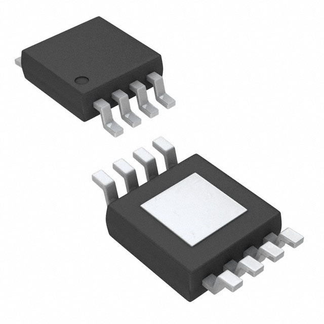
RT7277GSP

RT7277GSP

  • 厂商:

    RICHTEK(台湾立锜)

  • 封装:

    SOIC-8

  • 描述:

    IC REG BUCK ADJUSTABLE 3A 8SOP

  • 详情介绍
  • 数据手册
  • 价格&库存
RT7277GSP 数据手册
® RT7277 3A, 18V, 700kHz ACOTTM Synchronous Step-Down Converter General Description Features The RT7277 is a synchronous step-down DC/DC converter with Advanced Constant On-Time (ACOTTM) mode control. z It achieves high power density to deliver up to 3A output current from a 4.5V to 18V input supply. The proprietary ACOTTM mode offers an optimal transient response over a wide range of loads and all kinds of ceramic capacitors, which allows the device to adopt very low ESR output capacitors for ensuring performance stabilization. In addition, RT7277 keeps an excellent constant switching frequency under line and load variation and the integrated synchronous power switches with the ACOTTM mode operation provides high efficiency in whole output current load range. Cycle-by-cycle current limit provides an accurate protection by a valley detection of low side MOSFET and external soft-start setting eliminates input current surge during startup. Protection functions also include output under voltage protection, output over voltage protection, and thermal shutdown. z z z z z z z z z z z z z 4.5V to 18V Input Voltage Range 3A Output Current 60mΩ Ω Internal Low Site N-MOSFET Advanced Constant On-Time Control Support All Ceramic Capacitors Up to 95% Efficiency 700kHz Switching Frequency Adjustable Output Voltage from 0.765V to 8V Adjustable Soft-Start Cycle-by-Cycle Current Limit Input Under Voltage Lockout Thermal Shutdown RoHS Compliant and Halogen Free Applications z z z Marking Information z z RT7277GSP : Product Number RT7277 GSPYMDNN ACOTTM Mode Enables Fast Transient Response YMDNN : Date Code Industrial and Commercial Low Power Systems Computer Peripherals LCD Monitors and TVs Green Electronics/Appliances Point of Load Regulation for High-Performance DSPs, FPGAs, and ASICs Simplified Application Circuit RT7277 VIN SW VIN C1 C2 C6 BOOT Chip Enable EN FB SS PVCC C5 Copyright © 2013 Richtek Technology Corporation. All rights reserved. DS7277-01 March 2013 L1 GND C4 VOUT C7 C3 R1 VPVCC R2 is a registered trademark of Richtek Technology Corporation. www.richtek.com 1 RT7277 Ordering Information Pin Configurations (TOP VIEW) RT7277 Package Type SP : SOP-8 (Exposed Pad-Option 2) Lead Plating System G : Green (Halogen Free and Pb Free) Note : 8 FB 2 PVCC SS 3 4 GND 9 VIN 7 BOOT 6 SW 5 GND SOP-8 (Exposed Pad) Richtek products are : ` EN RoHS compliant and compatible with the current requirements of IPC/JEDEC J-STD-020. ` Suitable for use in SnPb or Pb-free soldering processes. Functional Pin Description Pin No. Pin Name Pin Function 1 EN Enable Input. A logic-high enables the converter; a logic-low forces the IC into shutdown mode reducing the supply current to less than 10μA. 2 FB Feedback Input. It is used to regulate the output of the converter to a set value via an external resistive voltage divider. The feedback threshold voltage is 0.765V typically. 3 PVCC Internal Regulator Output. Connect a 1μF capacitor to GND to stabilize output voltage. 4 SS Soft-Start Control Input. SS controls the soft-start period. Connect a capacitor from SS to GND to set the soft-start period. A 3.9nF capacitor sets the soft-start period of VOUT to 2.6ms. GND Ground. The Exposed pad should be soldered to a large PCB and connected to GND for maximum thermal dissipation. 6 SW Switch Node. Connect this pin to an external L-C filter. 7 BOOT Bootstrap Supply for High Side Gate Driver. Connect a 0.1μF or greater ceramic capacitor from BOOT to SW pins. 8 VIN Power Input. The input voltage range is from 4.5V to 18V. Must bypass with a suitably large ( ≥10μF x 2) ceramic capacitor. 5, 9 (Exposed Pad) Copyright © 2013 Richtek Technology Corporation. All rights reserved. www.richtek.com 2 is a registered trademark of Richtek Technology Corporation. DS7277-01 March 2013 RT7277 Function Block Diagram BOOT PVCC Internal Regulator VIN PVCC VIBIAS Over Current PVCC Protection VREF UGATE Switch Controller PVCC SW Driver Ripple Gen. LGATE GND SW 2µA + - - SS FB FB Comparator On-Time EN EN Operation In normal operation, the high side N-MOSFET is turned on when the FB Comparator sets the Switch Controller, and it is turned off when On-Time Controller resets the Switch Controller. While the high side N-MOSFET is turned off, the low side N-MOSFET is turned on and waits for the FB Comparator to set the beginning of next cycle. Enable The FB Comparator sets the Switch Controller by comparing the feedback signal (FB) from output voltage with the internal 0.765V reference. When load transient induces VOUT drop, the FB voltage will be less than its threshold voltage. This means that the high side N-MOSFET will turn on again immediately after minimum off-time expired. The switching frequency will vary during the transient period thus can provide a very fast transient response. After the load transient finished, the RT7277 will be back to steady state with a constant switching frequency. Provide internal power for logic control and switch gate drivers. Copyright © 2013 Richtek Technology Corporation. All rights reserved. DS7277-01 March 2013 Activate internal regulator once EN input level is higher than the target level. Force IC to enter shutdown mode when the EN input level is lower than 0.4V Internal Regulator On-Time Controller Control on-time according to VIN and SW to obtain constant switching frequency. is a registered trademark of Richtek Technology Corporation. www.richtek.com 3 RT7277 Absolute Maximum Ratings z z z z z z z z z z (Note 1) Supply Voltage, VIN ----------------------------------------------------------------------------------------------Switch Voltage, SW ----------------------------------------------------------------------------------------------
RT7277GSP
1. 物料型号: - 型号:RT7277 - 描述:3A, 18V, 700kHz ACOTTM同步降压转换器

2. 器件简介: - RT7277是一款具有先进恒定导通时间(ACOT)模式控制的同步降压DC/DC转换器,能够在4.5V至18V的输入电压下提供高达3A的输出电流。

3. 引脚分配: - 1号引脚(EN):使能输入,高电平启用转换器,低电平使IC进入关闭模式。 - 2号引脚(FB):反馈输入,用于调节输出电压至设定值。 - 3号引脚(PVCC):内部调节器输出,需连接1uF电容至地以稳定输出电压。 - 4号引脚(SS):软启动控制输入,通过连接电容至地来设定软启动周期。 - 5、9号引脚(GND, Exposed Pad):接地,Exposed Pad需焊接至大PCB并接地以获得最大散热效果。 - 6号引脚(SW):开关节点,连接至外部L-C滤波器。 - 7号引脚(BOOT):高侧栅极驱动的自举供电,需连接0.1uF或更大的陶瓷电容。 - 8号引脚(VIN):电源输入,输入电压范围为4.5V至18V,需旁路适合的大电容。

4. 参数特性: - 输入电压范围:4.5V至18V - 输出电流:3A - 内部低侧N-MOSFET:60mΩ - 效率:高达95% - 开关频率:700kHz - 可调输出电压:0.765V至8V

5. 功能详解: - 支持所有陶瓷电容器 - 700kHz开关频率 - 可调软启动 - 循环电流限制 - 输入欠压锁定 - 热关断保护

6. 应用信息: - 工业和商业低功耗系统 - 电脑外设 - 液晶显示器和电视 - 绿色电子/家电 - 高性能DSP、FPGA和ASIC的点负载调节

7. 封装信息: - SOP-8 (Exposed Pad) 封装,引脚镀层系统 - 绿色(无卤素和无铅) - 符合RoHS标准,兼容IPC/JEDEC J-STD-020要求,适用于SnPb或无铅焊接工艺。
RT7277GSP 价格&库存

很抱歉,暂时无法提供与“RT7277GSP”相匹配的价格&库存,您可以联系我们找货

免费人工找货