®
RT8074
4A, 2MHz, Synchronous Step-Down Converter
General Description
Features
The RT8074 is a high efficiency synchronous, step-down
DC/DC converter. Its input voltage range is from 2.7V to
5.5V and provides an adjustable regulated output voltage
from 0.8V to 5V while delivering up to 4A of output current.
z
High Efficiency : Up to 95%
z
Adjustable Frequency : 200kHz to 2MHz
No Schottky Diode Required
0.8V Reference Allows Low Output Voltage
Low Dropout Operation : 100% Duty Cycle
Enable Function
Internal Soft-Start
RoHS Compliant and Halogen Free
The internal synchronous low on-resistance power
switches increase efficiency and eliminate the need for
an external Schottky diode. The default switching
frequency is set at 2MHz, if the RT pin is left open. It can
also be varied from 200kHz to 2MHz by adding an external
resistor. Current mode operation with external
compensation allows the transient response to be
optimized over a wide range of loads and output capacitors.
z
z
z
z
z
z
Applications
z
z
z
z
Ordering Information
z
LCD TV and Monitor
Notebook Computers
Distributed Power Systems
IP Phones
Digital Cameras
RT8074
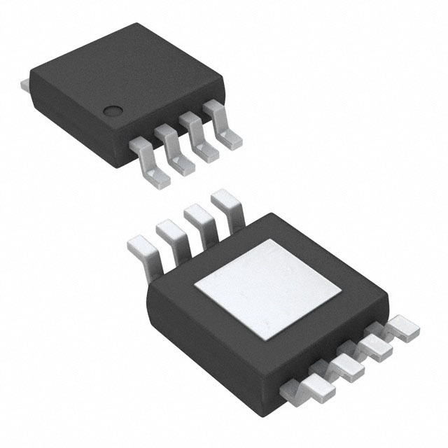
Package Type
SP : SOP-8 (Exposed Pad-Option 2)
Pin Configurations
Lead Plating System
G : Green (Halogen Free and Pb Free)
(TOP VIEW)
COMP
Note :
Richtek products are :
`
RoHS compliant and compatible with the current require-
8
GND
2
EN
3
7
GND
6
9
4
5
VIN
FB
RT
LX
LX
ments of IPC/JEDEC J-STD-020.
`
SOP-8 (Exposed Pad)
Suitable for use in SnPb or Pb-free soldering processes.
Typical Application Circuit
RT8074
VIN
2.7V to 5.5V
4
LX
VIN
CIN
10µF
FB
3 EN
COMP
L
5, 6
1.5µH
8
1
7 RT
COUT
22µF
RCOMP
10k
ROSC
R1
750
GND 2,
9 (Exposed Pad)
VOUT
1.1V
CCOMP
560pF
R2
2k
Note : Using all Ceramic Capacitors
Copyright © 2012 Richtek Technology Corporation. All rights reserved.
DS8074-07
November 2012
is a registered trademark of Richtek Technology Corporation.
www.richtek.com
1
�RT8074
Marking Information
RT8074GSP : Product Number
RT8074
GSPYMDNN
YMDNN : Date Code
Functional Pin Description
Pin No.
Pin Name
1
Pin Function
Error Amplifier Compensation Point. The current comparator threshold increases
with this control voltage. Connect external compensation elements to this pin to
stabilize the control loop.
COMP
2,
GND
9 (Exposed Pad)
Ground. The exposed pad must be soldered to a large PCB and connected to GND
for maximum power dissipation.
3
EN
Enable Control Input. Float or connect this pin to logic high for enable. Connect to
GND for disable.
4
VIN
Power Input Supply. Decouple this pin to GND with a capacitor.
5, 6
LX
Internal Power MOSFET Switches Output. Connect this pin to the inductor.
7
RT
Oscillator Resistor Input. Connecting a resistor from this pin to GND sets the
switching frequency. If this pin is floating, the frequency will be set at 2MHz
internally.
8
FB
Feedback. Receives the feedback voltage from a resistive divider connected across
the output.
Function Block Diagram
RT
SD
VIN
ISEN
OSC
Slope
Com
COMP
0.8V
FB
EA
Output
Clamp
OC
Limit
Driver
Int-SS
LX
Hiccup
Control
Logic
0.7V
EN
Enable
0.4V
P-G
UV
Copyright © 2012 Richtek Technology Corporation. All rights reserved.
www.richtek.com
2
NISEN
OTP
GND
N-MOS ILIM
is a registered trademark of Richtek Technology Corporation.
DS8074-07
November 2012
�RT8074
Absolute Maximum Ratings
z
z
z
z
z
z
z
z
z
z
(Note 1)
Supply Input Voltage, VIN --------------------------------------------------------------------------------------- −0.3V to 6.5V
LX Pin Switch Voltage -------------------------------------------------------------------------------------------- −0.3V to (VIN + 0.3V)
很抱歉,暂时无法提供与“RT8074GSP”相匹配的价格&库存,您可以联系我们找货
免费人工找货- 国内价格
- 1+3.01320
- 10+2.94840
- 30+2.89440
- 国内价格 香港价格
- 1+8.111741+1.04796
- 10+5.8359810+0.75396
- 25+5.2610125+0.67968
- 100+4.62625100+0.59767
- 250+4.32265250+0.55845
- 500+4.13983500+0.53483
- 1000+4.005741000+0.51751
- 国内价格 香港价格
- 2500+3.793382500+0.49007
- 5000+3.698555000+0.47782
- 7500+3.651107500+0.47169
- 12500+3.5984912500+0.46489
- 17500+3.5677317500+0.46092
- 国内价格
- 1+5.24320
- 10+3.87850
- 100+3.32440
- 1000+2.77030