®
RT9385
5 Channels 125mA x1/x1.5/x2 Charge Pump White LED Driver
General Description
Features
The RT9385 is a 5 Channel WLED driver with auto mode
selection of x1, x1.5 and x2 mode with low dropout voltage
in current sources. The RT9385 can power up to 5 white
z
85% Average Efficiency Over Li-ion Battery
Discharge
z
LEDs with regulated constant current for uniform intensity.
Each channel (LED1 to LED5) can support up to 25mA.
The part maintains highest efficiency by utilizing x1/x1.5/
x2 fractional charge pump and low dropout current
regulators. For the brightness control, user can easily use
a PWM signal generated from GPIO to control the
brightness of WLEDs.
z
Support Up to 5 White LEDs
Support Up to 25mA/Per Channel
PWM Brightness Control
60mV Current Source Dropout
1% LED Current Accuracy
0.7% LED Current Matching
Automatic x1/x1.5/x2 Charge Pump Mode
Transition
Low Input Noise and EMI
Over Voltage Protection
Power On/Mode Transition Inrush Protection
1MHz Switching Frequency
0.4μ
μA Low Shutdown Current
RoHS Compliant and Halogen Free
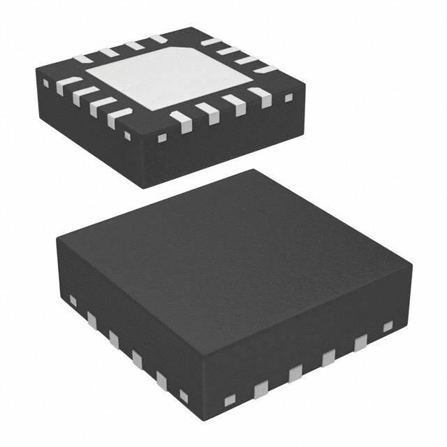
The RT9385 is available in a WQFN-16L 2x3 package.
Small 1μF capacitors can be used for fly capacitors. It
provides the best backlighting solution with high efficiency
and smallest board space for portable application.
z
z
z
z
z
z
z
z
z
z
Ordering Information
RT9385
Package Type
QW : WQFN-16L 2x3 (W-Type)
Lead Plating System
G : Green (Halogen Free and Pb Free)
Note :
Richtek products are :
`
z
Applications
z
z
Camera Phone, Smart Phone
White LED Backlighting
Pin Configurations
(TOP VIEW)
RoHS compliant and compatible with the current
LED2
LED1
VIN
requirements of IPC/JEDEC J-STD-020.
Suitable for use in SnPb or Pb-free soldering
processes.
Marking Information
For marking information, contact our sales representative
directly or through a Richtek distributor located in your
area.
Copyright © 2014 Richtek Technology Corporation. All rights reserved.
DS9385-02 January 2014
16 15 14
LED3
LED4
LED5
VOUT
PGND
1
13
2
12
GND
3
4
17
5
11
10
9
6
AGND
CF
VIN
EN
C2P
7 8
C2N
C1N
C1P
`
WQFN-16L 2x3
is a registered trademark of Richtek Technology Corporation.
www.richtek.com
1
�RT9385
Typical Application Circuit
CFLY2
1µF
CFLY1
1µF
7
8
C1P
14,11
CIN
1µF
6
9
C1N C2P C2N
VIN
PWM Input
10 EN
LED1
LED2
LED3
LED4
LED5
RT9385
4 VOUT
COUT
1µF
12 CF
CCF
0.1µF
AGND
13
15
16
1
2
3
PGND
5
Functional Pin Description
Pin No.
Pin Name
Pin Function
1
2
LED3
LED4
Current Sink for LED3. (If not in use, this pin should be connected to VIN)
Current Sink for LED4. (If not in use, this pin should be connected to VIN)
3
LED5
Current Sink for LED5. (If not in use, this pin should be connected to VIN)
4
VOUT
Charge Pump Output.
5
PGND
Ground.
6
C2N
Fly Capacitor 2 Negative Connection.
7
C1N
Fly Capacitor 1 Negative Connection.
8
C1P
Fly Capacitor 1 Positive Connection.
9
C2P
Fly Capacitor 2 Positive Connection.
10
EN
Chip Enable (Active High).
11, 14
VIN
Power Input.
12
CF
PWM Filter Capacitor Connection, No Connection if this pin is not in use.
13
AGND
Ground.
15
LED1
Current Sink for LED1. (If not in use, this pin should be connected to VIN)
16
LED2
Current Sink for LED2. (If not in use, this pin should connected to VIN)
17 (Exposed Pad) GND
The exposed pad must be soldered to a large PCB and connected to GND for
maximum power dissipation.
Copyright © 2014 Richtek Technology Corporation. All rights reserved.
www.richtek.com
2
is a registered trademark of Richtek Technology Corporation.
DS9385-02 January 2014
�RT9385
Function Block Diagram
C1P
C1N C2P C2N
VIN
VOUT
Soft Start
Circuit
OVP
UVLO
Gate Driver
1MHz
OSC
Mode Decision
CF
EN
PGND
AGND
Shutdown Delay
Current
Bias
Copyright © 2014 Richtek Technology Corporation. All rights reserved.
DS9385-02 January 2014
LED1
LED2
LED3
LED4
LED5
PWM Dimming
Controller
Current Source
is a registered trademark of Richtek Technology Corporation.
www.richtek.com
3
�RT9385
Absolute Maximum Ratings
z
z
z
z
z
z
z
(Note 1)
Supply Input Voltage, VIN -----------------------------------------------------------------------------------------------Power Dissipation, PD @ TA = 25°C
WQFN-16L 2x3 -----------------------------------------------------------------------------------------------------------Package Thermal Resistance (Note 2)
WQFN-16L 2x3, θJA ------------------------------------------------------------------------------------------------------WQFN-16L 2x3, θJC -----------------------------------------------------------------------------------------------------Junction Temperature ----------------------------------------------------------------------------------------------------Lead Temperature (Soldering, 10 sec.) ------------------------------------------------------------------------------Storage Temperature Range -------------------------------------------------------------------------------------------ESD Susceptibility (Note 3)
HBM (Human Body Mode) ---------------------------------------------------------------------------------------------MM (Machine Mode) ------------------------------------------------------------------------------------------------------
Recommended Operating Conditions
z
z
−0.3V to 5V
1.111W
90°C/W
15°C/W
150°C
260°C
−65°C to 150°C
2kV
200V
(Note 4)
Junction Temperature Range -------------------------------------------------------------------------------------------- −40°C to 125°C
Ambient Temperature Range -------------------------------------------------------------------------------------------- −40°C to 85°C
Electrical Characteristics
(VIN = 3.6V, VF = 3.5V, CIN = COUT = 1uF, CFLY1 = CFLY2 = 1μF, ILED1 to LED5 = 25mA, TA = 25°C, unless otherwise specified)
Parameter
Symbol
Test Conditions
Min
Typ
Max
Unit
2.8
--
4.5
V
1.8
2
2.5
V
--
100
--
mV
Input Power Supply
Input Supply Voltage
Under-Voltage Lockout
Threshold
Under-Voltage Lockout
Hysteresis
VIN
VUVLO
VIN Rising
ΔV UVLO
Quiescent Current
IQ
x1 Mode
--
1
2
mA
Shutdown Current
ISHDN
VIN = 4.5V
--
0.4
2
μA
ILEDx
ILEDx = 25mA
−5
0
+5
%
ILEDx = 25mA
−2
0
+2
%
--
1000
--
kHz
PWM Dimming Frequency
1
--
200
kHz
Internal CF Resistance
--
160
--
kΩ
LED Current
LED Current Accuracy
Current Matching
Charge Pump
Oscillator Frequency
fOSC
Mode Decision
x1 Mode to x1.5 Mode
Transition Voltage (VIN Falling)
IOUT = 125mA, ILEDx = 25mA.
--
3.65
3.8
V
Mode Transition Hystersis
IOUT = 125mA, ILEDx = 25mA.
--
200
--
mV
Copyright © 2014 Richtek Technology Corporation. All rights reserved.
www.richtek.com
4
is a registered trademark of Richtek Technology Corporation.
DS9385-02 January 2014
�RT9385
Parameter
Symbol
Test Conditions
Min
Typ
Max
Unit
4.5
5
5.5
V
3
--
--
ms
Protection
OVP
V IN – VOUT
Enable
EN Low Time for Shutdown
EN
Threshold
Logic-Low Voltage
V IL
--
--
0.2
Logic-High Voltage
V IH
1
--
4.5
--
2
--
EN Pull Low Current
V
μA
Note 1. Stresses listed as the above "Absolute Maximum Ratings" may cause permanent damage to the device. These are for
stress ratings. Functional operation of the device at these or any other conditions beyond those indicated in the
operational sections of the specifications is not implied. Exposure to absolute maximum rating conditions for extended
periods may remain possibility to affect device reliability.
Note 2. θJA is measured in the natural convection at TA = 25°C on a high effective four layers thermal conductivity test board of
JEDEC 51-7 thermal measurement standard. The case point of θJC is on the exposed pad for the package.
Note 3. Devices are ESD sensitive. Handling precaution is recommended.
Note 4. The device is not guaranteed to function outside its operating conditions.
Copyright © 2014 Richtek Technology Corporation. All rights reserved.
DS9385-02 January 2014
is a registered trademark of Richtek Technology Corporation.
www.richtek.com
5
�RT9385
Typical Operating Characteristics
LED Current vs. Input Voltage
Efficiency vs. Input Voltage
100
90
LED Current (mA)
80
Efficiency (%)
70
60
50
40
30
20
10
LED VF = 3.02V
0
2.8
3
3.2 3.4 3.6 3.8
4
4.2 4.4 4.6 4.8
30
29
28
27
26
25
24
23
22
21
20
19
18
17
16
15
LED1
LED2
LED3
LED4
LED5
LED VF = 3.02V
2.8
5
3
4
4.2 4.4 4.6 4.8
5
Input Voltage (V)
Input Voltage (V)
x2 Mode Quiescent Current vs. Input Voltage
x1 Mode Quiescent Current vs. Input Voltage
1.30
4.5
1.25
Quiescent Current (mA)
Quiescent Current (mA)
3.2 3.4 3.6 3.8
1.20
1.15
1.10
1.05
1.00
4.0
3.5
3.0
2.5
2.0
2.8
3
3.2 3.4 3.6 3.8
4
4.2 4.4 4.6 4.8
5
2.8
3
3.2 3.4 3.6 3.8
4
4.2 4.4 4.6 4.8
Input Voltage (V)
Input Voltage (V)
Shutdown Current vs. Input Voltage
x1 Mode Inrush Current Response
5
1
Shutdown Current (μA)
0.9
EN
(5V/Div)
0.8
0.7
VOUT
(1V/Div)
0.6
0.5
C2P
(2V/Div)
0.4
0.3
0.2
IIN
(200mA/Div)
0.1
VIN = 3.2V
0
2.8
3
3.2 3.4 3.6 3.8
4
4.2 4.4 4.6 4.8
5
Time (100μs/Div)
Input Voltage (V)
Copyright © 2014 Richtek Technology Corporation. All rights reserved.
www.richtek.com
6
is a registered trademark of Richtek Technology Corporation.
DS9385-02 January 2014
�RT9385
x1.5 Mode Inrush Current Response
x2 Mode Inrush Current Response
EN
(5V/Div)
VIN = 3.15V
EN
(5V/Div)
VIN = 3.1V
VOUT
(1V/Div)
VOUT
(1V/Div)
C2P
(2V/Div)
C2P
(2V/Div)
IIN
(200mA/Div)
IIN
(200mA/Div)
Time (100μs/Div)
Time (100μs/Div)
PWM Dimming Operation
Ripple & Spike
VIN = 3.7V, CCF = 56nF, Duty = 50%, f = 10kHz
EN
(2V/Div)
VIN
(50mV/Div)
VOUT
(50mV/Div)
C2P
(5V/Div)
ILED
(10mA/Div)
IIN
(200mA/Div)
Time (250μs/Div)
Copyright © 2014 Richtek Technology Corporation. All rights reserved.
DS9385-02 January 2014
VIN = 3.1V
Time (1μs/Div)
is a registered trademark of Richtek Technology Corporation.
www.richtek.com
7
�RT9385
Applications Information
The RT9385 uses a fractional switched capacitor charge
pump to power up to five white LEDs with a programmable
current for uniform intensity. The part integrates current
sources and automatic mode selection charge pump. It
maintains the high efficiency by utilizing an x1/x1.5/x2
fractional charge pump and current sources. The small
equivalent x1 mode open loop resistance and ultra-low
dropout voltage of current source extend the operating
time of x1 mode and optimize the efficiency in white LED
applications.
Input UVLO
The input operating voltage range of the LED driver is from
2.8V to 4.5V. An input capacitor at the VIN pin could reduce
ripple voltage. It is recommended to use a ceramic 1μF or
larger capacitance as the input capacitor. The RT9385
provides an under voltage lockout (UVLO) function to
prevent it from unstable issue when startup. The UVLO
threshold of input rising voltage is set at 2V typically with
a hysteresis of 100mV.
Capacitors Selection
To get the better performance of the RT9385, the selection
of peripherally appropriate capacitor and value is very
important. These capacitors determine some parameters
such as input/output ripple voltage, power efficiency and
maximum supply current by charge pump. To reduce the
input and output ripple effectively, the low ESR ceramic
capacitors are recommended. For LED driver applications,
the input voltage ripple is more important than output
ripple. Input ripple is controlled by input capacitor CIN,
increasing the value of input capacitance can further reduce
the ripple. Practically, the input voltage ripple depends on
the power supply impedance. The flying capacitor CFLY1
and CFLY2 determine the supply current capability of the
charge pump to influence the overall efficiency of the
system. The lower value will improve efficiency. However,
it will limit the LED's current at low input voltage. For
5x25mA load over the entire input range of 2.8V to 4.5V, it
is recommended to use a 1μF ceramic capacitor on the
flying capacitor CFLY1 and CFLY2.
Soft Start
Brightness Control
The charge pump employs a soft start feature to limit the
inrush current. The soft-start circuit prevents the excessive
inrush current and input voltage drop. The soft-start clamps
the input current in a typical period of 50μs.
The RT9385 implements a PWM dimming method to
control the brightness of white LEDs. When an external
PWM signal is connected to the EN pin, brightness of
white LED is adjusted by the duty cycle. The suggested
PWM dimming frequency range is from 1kHz to 200kHz.
Mode Decision
The RT9385 uses a smart mode selection method to decide
the working mode for optimizing the efficiency. Mode
decision circuit senses the output and LED voltage for
up/down selection. The RT9385 automatically switches
to x1.5 or x2 mode whenever the dropout condition is
detected from the current source and returns to x1 mode
whenever the dropout condition releases.
LED connection
The RT9385 supports up to 5 white LEDs. The 5 LEDs
are connected from VIN to pin1, 2, 3, 15 and 16
respectively. If the LED is not used, the LED pin should
be connected to VIN directly.
Thermal Considerations
For continuous operation, do not exceed absolute
maximum operation junction temperature. The maximum
power dissipation depends on the thermal resistance of
IC package, PCB layout, the rate of surroundings airflow
and temperature difference between junction to ambient.
The maximum power dissipation can be calculated by
following formula :
PD(MAX) = ( TJ(MAX) − TA ) / θJA
Where T J(MAX) is the maximum operation junction
temperature, TA is the ambient temperature and the θJA is
the junction to ambient thermal resistance.
For recommended operating conditions specification of
Copyright © 2014 Richtek Technology Corporation. All rights reserved.
www.richtek.com
8
is a registered trademark of Richtek Technology Corporation.
DS9385-02 January 2014
�RT9385
PD(MAX) = (125°C − 25°C) / (90°C/W) = 1.111W for
WQFN-16L 2x3 package
The maximum power dissipation depends on operating
ambient temperature for fixed T J(MAX) and thermal
resistance θJA. For RT9385 package, the Figure 1 of
derating curve allows the designer to see the effect of
rising ambient temperature on the maximum power
dissipation allowed.
Four Layers PCB
1.1
1.0
0.9
`
The traces running from pins to flying capacitor should
be short and wide to reduce parasitic resistance and
prevent noise radiation.
All the traces of LED pins running from
chip to LEDs should be wide and short to
reduce the parasitic connection resistance.
Output capacitor
(COUT) should
be placed close
to VOUT and
connected to
ground plane to
reduce noise
coupling from
charge pump to
LEDs.
The trace from CF pin
to external capacitance
should be as short as
possible.
16 15 14
LED3
1
13
AGND
LED4
2
12
CF
LED5
3
11
VIN
VOUT
4
10
EN
GND
Battery
Input capacitor
(CIN) should be
6 7 8
placed close to VIN
and connected to
ground plane. The
trace of VIN in the
GND
GND PCB should be
placed far away
The traces running from pins to flying capacitor from the sensitive
should be short and wide to reduce parasitic
devices or shielded
resistance and prevent noise radiation.
by the ground.
WQFN-16L 2x3
0.8
Input capacitor (CIN) should be placed close to VIN and
connected to ground plane. The trace of VIN in the PCB
should be placed far away from the sensitive devices or
shielded by the ground.
PGND
5
17
9
C2P
C2N
C1N
C1P
Maximum Power Dissipation (W)
1.2
`
LED2
LED1
VIN
the RT9385, The maximum junction temperature is 125°C.
The junction to ambient thermal resistance θJA is layout
dependent. For WQFN-16L 2x3 package, the thermal
resistance θJA is 90°C/W on the standard JEDEC 51-7
four layers thermal test board. The maximum power
dissipation at TA = 25°C can be calculated by following
formula :
0.7
0.6
0.5
0.4
0.3
0.2
0.1
Figure 2. PCB Layout Guide
0.0
0
25
50
75
100
125
Ambient Temperature (°C)
Figure 1. Derating Curve for RT9385 Package
Layout Considerations
For best performance of the RT9385, the following layout
guidelines should be strictly followed :
`
Output Capacitor (COUT) should be placed close to VOUT
and connected to ground plane to reduce noise coupling
from charge pump to LEDs.
`
All the traces of LED pins running from chip to LED's
should be wide and short to reduce the parasitic
connection resistance.
`
The trace from CF pin to external capacitance should
be as short as possible.
Copyright © 2014 Richtek Technology Corporation. All rights reserved.
DS9385-02 January 2014
is a registered trademark of Richtek Technology Corporation.
www.richtek.com
9
�RT9385
Outline Dimension
D
D2
SEE DETAIL A
e
E
E2
L
b
1
1
2
2
A
A1
A3
DETAIL A
Pin #1 ID and Tie Bar Mark Options
Note : The configuration of the Pin #1 identifier is optional,
but must be located within the zone indicated.
Symbol
Dimensions In Millimeters
Dimensions In Inches
Min
Max
Min
Max
A
0.700
0.800
0.028
0.031
A1
0.000
0.050
0.000
0.002
A3
0.175
0.250
0.007
0.010
b
0.150
0.250
0.006
0.010
D
1.900
2.100
0.075
0.083
D2
0.700
0.800
0.028
0.031
E
2.900
3.100
0.114
0.122
E2
1.700
1.800
0.067
0.071
e
L
0.400
0.325
0.016
0.425
0.013
0.017
W-Type 16L QFN 2x3 Package
Richtek Technology Corporation
14F, No. 8, Tai Yuen 1st Street, Chupei City
Hsinchu, Taiwan, R.O.C.
Tel: (8863)5526789
Richtek products are sold by description only. Richtek reserves the right to change the circuitry and/or specifications without notice at any time. Customers should
obtain the latest relevant information and data sheets before placing orders and should verify that such information is current and complete. Richtek cannot
assume responsibility for use of any circuitry other than circuitry entirely embodied in a Richtek product. Information furnished by Richtek is believed to be
accurate and reliable. However, no responsibility is assumed by Richtek or its subsidiaries for its use; nor for any infringements of patents or other rights of third
parties which may result from its use. No license is granted by implication or otherwise under any patent or patent rights of Richtek or its subsidiaries.
www.richtek.com
10
DS9385-02 January 2014
�


 工商网监
湘ICP备2023018690号
工商网监
湘ICP备2023018690号
